ABSTRACT
The residual vibration during the high acceleration and deceleration of a motion stage degrades the manufacturing-system productivity and lifespan. Although a passive RFC mechanism with a movable magnet track reduces the residual vibration of the system base, a magnet track resonance may occur according to the motion profile, and the mover in-position error increases due to the residual vibration of the magnet track. We investigated input-shaping methods for a linear motor motion stage with a passive RFC mechanism. An air-bearing linear motor motion stage with the passive RFC mechanism is built, and the dynamic characteristic of the passive RFC mechanism is identified using a free-vibration test. Then, mover velocity profiles are generated using various input-shaping methods. Further, the effects of the input-shaping methods on the air-bearing linear motor motion stage are investigated by comparing the magnet track oscillation, settling time, and mover in-position error. Finally, several input-shaping methods are applied to reduce the mover rise-time delay for the proposed linear motor motion stage. A properly shaped input motion profile removes the residual vibration of the passive RFC mechanism without any additional devices, as well as reducing the transmitted reaction force and the in-position error.
-
KEYWORDS: Linear motor motion stage, Residual vibration, Reaction force compensation, Input-shaping method
-
KEYWORDS: 선형 모터 모션 스테이지, 잔류 진동, 반발력 보상, 입력 성형 기법
NOMENCLATURE
Displacement of magnet track
Acceleration of magnet track
1. Introduction
Moving mass and working area increases associated with enlarged size such as display panel and semiconductor industries require fast response and high precision of a motion stage. In particular, semi-conductor lithography systems require both extreme precision and high speed in very long stroke such as 1 nanometer accuracy and 230 wafers/hour over 2 m stroke.
1,2
Residual vibration of the system base due to high speed motion has a negative effect on production quality, manufacturing process time and life of the manufacturing equipment. Rapid acceleration or deceleration motion of a stage induces large reaction force and causes the system base to oscillate either with unacceptable amplitude or in long settling time.
3
Base vibration of a linear motor motion stage has been reduced with a passive reaction force compensation (RFC) mechanism.
4,5 Although the passive RFC mechanism is compact and cost-effective without any additional external structures or actuator, the passive RFC does not allow in-situ modification of the dynamic characteristic and may have resonance when a motion profile excites natural frequency of the RFC mechanism.
4 An active RFC mechanism using an additional coil can tune its stiffness of the magnet track, and minimize the transmitted force under motion profile variations.
6 However, the active RFC mechanism results in increasing energy and cost requirements due to extra servo amplifier and motion controller.
7 In addition, an eddy-current damper is used to dissipate the residual vibration of the magnet track as an alternative way.
8,9
Input-shaping method is widely used to reduce mechanical vibration of a motion control system since it generates a command that cancels its own vibration and does not need an additional sensor for feedback control.
10,11 Since the input-shaping method is implemented by convolving a sequence of impulse so that rise time of the motion is delayed proportional to the natural frequency of the vibration. Input-shaping method may resolve residual vibration of the passive RFC mechanism without any additional devices.
This paper presents input-shaping methods for a linear motor motion stage with a passive RFC mechanism. First, an air-bearing linear motor motion stage with the passive RFC mechanism is built for experimental verification and dynamic characteristic of the passive RFC mechanism is identified with free vibration test. Then, velocity profiles of the mover are generated with various input-shaping methods. In addition, we investigate effects of input-shaping methods on the linear motor motion stage with the passive RFC mechanism by comparing the magnet track oscillation, settling time and in-position error of the mover. Finally, special input-shaping methods to reduce the rise time delay of the mover are investigated for the linear motor motion stage with the passive RFC.
2. Passive RFC Mechanism for a Linear Motor Motion Stage
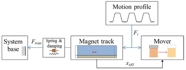
Fig. 1 shows the schematics of the passive RFC mechanism. When the mover moves due to thrust force (
Ft), its reaction force makes the magnet track with dummy mass (
mMT) oscillate and create displacement (
xMT) since the magnet track is supported by spring (
kMT) and damper (
cMT).
4,5 The equation of motion of the passive RFC mechanism is given by
Eq. (1).
Fig. 1 The passive RFC for a linear motion stage
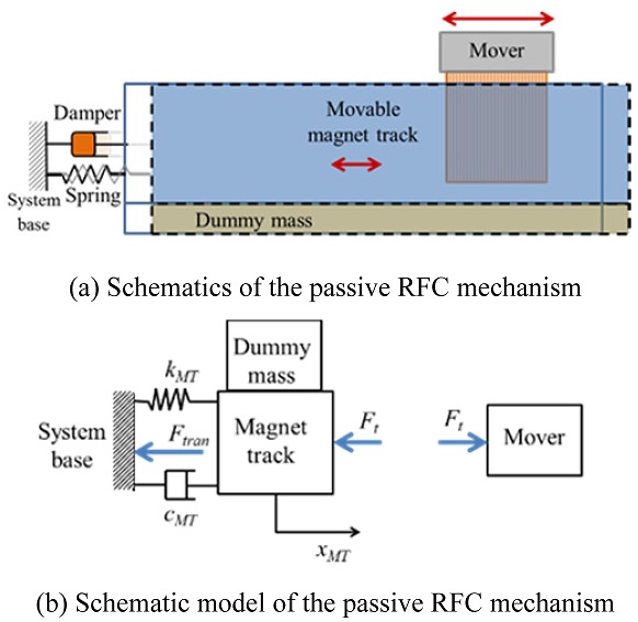
The transmitted force to the system base through spring and damping is expressed with
Eq. (2). The reaction force (
Ft) is divided into the inertial force of the magnet track and the force of the spring and the damper transmitted to the system base. The magnet track displacement and the transmitted force can be adjusted by changing the dummy mass and the spring stiffness.
The passive RFC mechanism may have residual oscillation of the magnet track after a mover motion so that mover jitter may increase, as shown in
Fig. 2. Although the magnet track oscillation reduces transmitted force to the system base (
Ft →
Ftran), the motion jitter after motion may become large when the motion profile excites natural frequency of the magnet track.
Fig. 2 Mover jitter increase due to magnet track oscillation

3. Air-Bearing Linear Motion Stage with the Passive RFC Mechanism
3.1 Constitution and Specifications
An air-bearing linear motor motion stage with the passive RFC mechanism is built, as shown in
Fig. 3. The specifications of the stage are summarized in
Table 1. The stage has in-position error within ± 0.4
μm, straightness with 4.3
μm and flatness within 1.7
μm.
Fig. 3An air-bearing linear motor motion stage with the passive RFC
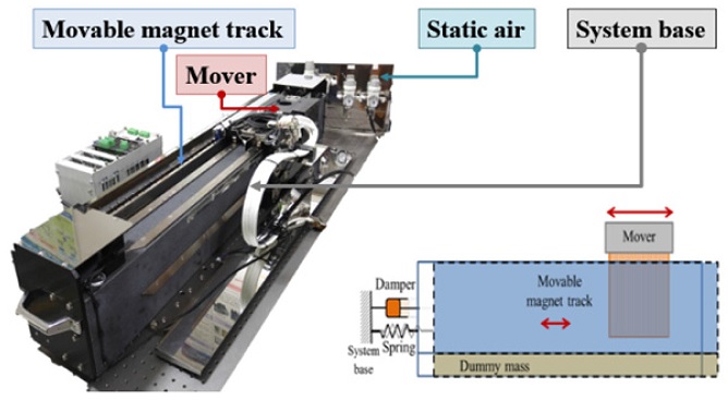
Table 1Specifications of an air-bearing linear motor motion stage
Table 1
|
Items |
Unit |
Value |
|
Stroke |
mm |
580 |
|
Force (Continuous/Peak) |
N |
208/832 |
|
Resolution |
μm |
1 |
|
Max. speed |
m/s |
5 |
|
Max. acc |
m/s2
|
50 |
3.2 System Identification of the Passive RFC Mechanism
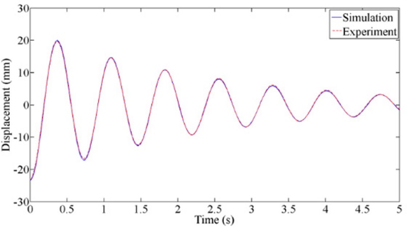
Since dynamic characteristic of the passive RFC mechanism is necessary to apply an input-shaping method, modal parameters of the passive RFC mechanism are identified with free vibration test of
Fig. 4 and summarized in
Table 2.
Fig. 4System identification of modal parameters of the passive RFC mechanism

Table 2Model parameters of the passive RFC mechanism
Table 2
|
Parameters |
Unit |
Value |
|
Mass of magnet track |
kg |
51.67 |
|
Stiffness |
N/m |
3820 |
|
Damping |
Ns/m |
45 |
|
Damped natural frequency |
Hz |
1.37 |
4. Input-Shaping Method for the Air-Bearing Linear Motor Motion Stage with the Passive RFC
4.1 ZV and ZVD Methods
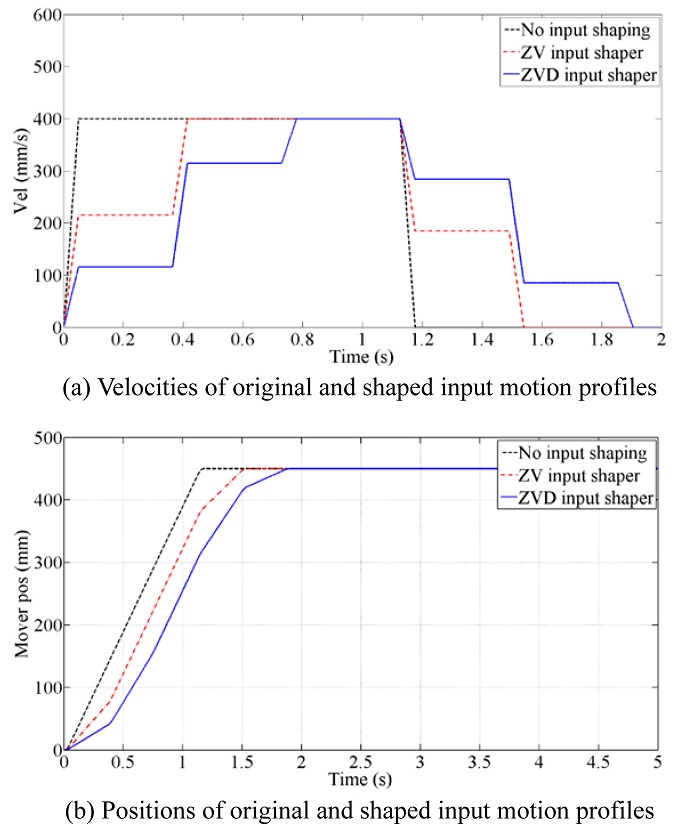
Input motion profiles with ZV (zero-velocity) and ZVD (zero-velocity derivative) methods
10 are compared with the original motion profile and shown in
Fig. 5. The original motion profile has max. 400 mm/s velocity and 450 mm stroke to intentionally excite large residual vibration of the magnet track (or to excite the resonance of the passive RFC).
4
Fig. 5Original and shaped input motion profiles

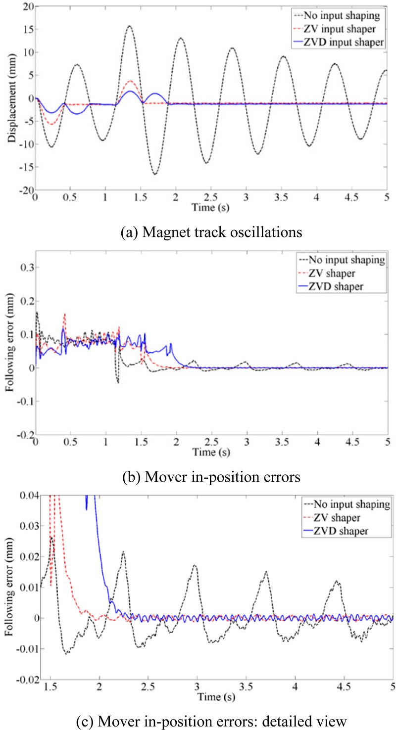
Magnet oscillation and the mover in-position errors for three motions profiles are shown in
Fig. 6. As shown in
Fig. 6(a), magnet track oscillations for the shaped inputs disappear after motion while the original motion profile generates large residual oscillation of the magnet track. In addition, mover in-position errors can be reduced significantly with the shaped motion profiles, as shown in
Figs. 6(b) and
6(c). Magnet track oscillations and mover in-position errors are quantitatively summarized during and after motion, as shown in
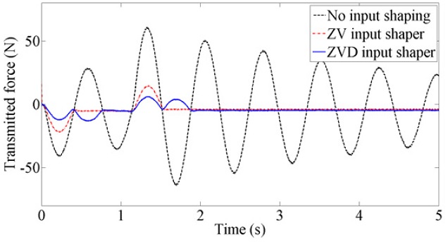
Table 3. Magnet track oscillation and mover in-position errors are reduced even during the motion. In addition, the transmitted force is reduced considerably with the shaped input motion profiles because the transmitted force is proportional to the magnet track oscillation.
Fig. 7 show the transmitted force for three motion profiles. The transmitted forces are significantly reduced with the input-shaping methods since the magnet track oscillations decreases.
Fig. 6Magnet trach oscillations and mover in-position errors for original and shaped input motion profiles

Table 3Comparisons of ZV and ZVD methods during and after motion
Table 3
|
|
ZV |
ZVD |
|
During motion |
Magnet track oscillation |
46.3 % |
67.1 % |
|
In-position error |
3.78 % |
29.39 % |
|
After motion |
Magnet track oscillation |
89.9 % |
91.4 % |
|
In-position error |
94.3 % |
93.9 % |
Fig. 7Transmitted force: original and shaped input motion profiles
4.2 Compensation of Delayed Rise Time of Input-Shaping
Two special input-shaping methods: 5f virtual mode input shaper (5f VMIS)
12 and max. speed-up input shaper (MSIS)
13 to compensate the delayed rise time of the mover are compared with the original and ZV motion profiles in
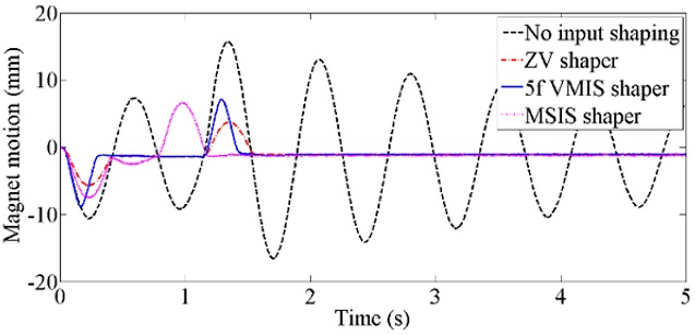
Fig. 8. ZVD has longer rise time delay than ZV and is not included in comparison. In addition, magnet track oscillations of two motion profiles are compared with those of the original and ZV motion profiles in
Fig. 9. Although the magnet track oscillation is larger than ZV input shaper during motions, magnet track oscillations almost disappear after motions. MSIS shows better performance than 5f VMIS in terms of magnet track oscillations.
Fig. 8Two special shaped motion profiles to compensate delayed rise time

Fig. 9Magnet track oscillations of two special shaped motion profiles

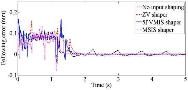
Mover in-position errors of two motion profiles are compared with those of the original and ZV motion profiles in
Fig. 10. In addition magnet track oscillations and mover in-position errors of two input-shaping methods are quantitatively summarized during and after motion, as shown in
Table 4. Mover following error of MSIS is smaller than ZV and 5f VMIS both during and after motions. In particular, MSIS shows much better performance than ZV and 5f VMIS in terms of in-position errors.
Fig. 10Mover in-position errors of two special shaped motion profiles

Table 4Comparisons of ZV, 5f VMIS and MSIS methods during and after motion
Table 4
|
|
ZV |
5fVMIS |
MSIS |
|
During motion |
Magnet track oscillation |
46.3 % |
16.8 % |
67.1 % |
|
In-position error |
3.78 % |
3.0 % |
29.39 % |
|
After motion |
Magnet track oscillation |
89.9 % |
92.2 % |
91.4 % |
|
In-position error |
94.3 % |
91.2 % |
93.9 % |
5. Conclusion
This paper presents input-shaping methods for a linear motor motion stage with a passive RFC mechanism. We built an air-bearing linear motor motion stage with the passive RFC mechanism and investigated effect of input-shaping methods on the linear motor motion stage with passive RFC mechanism by comparing the magnet oscillation and in-position error of the mover. In addition, special input-shaping methods to reduce the rise time delay of the mover are investigated for the linear motor motion stage with the passive RFC. Properly shaped input motion profile such as ZVD or MSIS not only removes residual vibration of the passive RFC mechanism without any additional devices but also reduce transmitted reaction force and in-position error.
ACKNOWLEDGMENTS
This work was by Basic Science Research Program through the National Research Foundation of Korea (NRF) funded by the Ministry of Education, Science and Technology (NRF-2013R1A1A2010764).
REFERENCES
- 1.
ASML, “TWINSCAN NXT: 1960Bi,” http://www.asml.com/asml/show.do?lang=EN&ctx=46772&dfp_product_id=7414 (Accessed 13 NOV 2017)
- 2.
Woo, S. and Gweon, D.-G., “Design and Optimization of Long Stroke Planar Motion Maglev Stage using Copper Strip Array,” Int. J. Precis. Eng. Manuf., Vol. 16, No. 3, pp. 479-485, 2015
10.1007/s12541-015-0065-6
- 3.
Pham, M. N. and Ahn, H.-J., “Horizontal Active Vibration Isolator (HAVI) Using Electromagnetic Planar Actuator (EPA),” Int. J. Precis. Eng. Manuf.-Green Tech., Vol. 2, No. 3, pp. 269-274, 2015.
10.1007/s40684-015-0032-9
- 4.
You, Y. H. and Ahn, H.-J., “A Passive Reaction Force Compensation (RFC) Mechanism for a Linear Motor Motion Stage,” Int. J. Precis. Eng. Manuf., Vol. 15, No. 5, pp. 797-801, 2014.
10.1007/s12541-014-0402-1
- 5.
Nguyen, D. C. and Ahn, H.-J., “Dynamic Analysis and Iterative Design of a Passive Reaction Force Compensation Device for a Linear Motor Motion Stage,” Int. J. Precis. Eng. Manuf., Vol. 15, No. 11, pp. 2376-2373, 2014.
10.1007/s12541-014-0602-8
- 6.
Nguyen, D. C. and Ahn, H.-J., “A Fuzzy-P Controller of an Active Reaction Force Compensation (RFC) Mechanism for a Linear Motor Motion Stage,” Int. J. Precis. Eng. Manuf., Vol. 16, No. 6, pp. 1067-1074, 2015.
10.1007/s12541-015-0138-6
- 7.
Nguyen, D. C. and Ahn, H.-J., “Semi-Active Reaction Force Compensation for a Linear Motor Motion Stage,” Int. J. Precis. Eng. Manuf., Vol. 17, No. 7, pp. 857-862, 2016.
10.1007/s12541-016-0104-y
- 8.
Ahn, H.-J., “Eddy Current Damper Type Reaction Force Compensation Mechanism for Linear Motor Motion Stage,” Int. J. Precis. Eng. Manuf.-Green Tech., Vol. 3, No. 1, pp. 67-74, 2016.
10.1007/s40684-016-0009-3
- 9.
Ahn, H.-J., Hwang, K. J., and Nguyen, D. C., “Eddy Current Damper for Passive Reaction Force Compensation of a Linear Motor Motion Stage,” Proceedings of the Institution of Mechanical Engineers, Part I: Journal of Systems and Control Engineering, Vol. 231, No. 5, pp. 360-366, 2017.
10.1177/0959651816650568
- 10.
Singhose, W., “Command Shaping for Flexible Systems: A Review of the First 50 Years,” Int. J. Precis. Eng. Manuf., Vol. 10, No. 4, pp. 153-168, 2009.
10.1007/s12541-009-0084-2
- 11.
Veciana, J. M., Cardona, S., and Català, P., “Modified Adaptive Input Shaping for Maneuvering Cranes Using a Feedback MEM Gyroscope with Null Drift,” Int. J. Precis. Eng. Manuf., Vol. 16, No. 9, pp 1911-1917, 2015.
10.1007/s12541-015-0248-1
- 12.
Jang, J. W., Park, S. W., and Hong, S. W., “Precise Positioning of High-Speed XY Stage by Improved Input Shaping,” Proc. of the Korean Society of Machine Tool Engineers Fall Conference, pp. 203-206, 2007.
- 13.
Li, H., Le, M. D., Gong, Z. M., and Lin, W., “Motion Profile Design to Reduce Residual Vibration of High-Speed Positioning Stage,” IEEE/ASME Transactions on Mechatronics, Vol. 14, No. 2, pp. 264-269, 2009.
10.1109/TMECH.2008.2012160
Citations
Citations to this article as recorded by

- Fuzzy Neural Network Control for a Reaction Force Compensation Linear Motor Motion Stage
Kyung Ho Yang, Hyeong-Joon Ahn
International Journal of Precision Engineering and Manufacturing-Smart Technology.2024; 2(2): 109. CrossRef - Software-Based Integral Product Architecture for Modular Motion Control System of a RFC Linear Motor Motion Stage: Model-Based DOB for Residual Vibration Suppression
Seong Jong Yoo, Hyeong-Joon Ahn
International Journal of Precision Engineering and Manufacturing.2020; 21(2): 203. CrossRef - Evaluation of Input Shaping Methods for the Nonlinear Vibration System Using a Furuta Pendulum
Anh-Duc Pham, Hyeong-Joon Ahn
Journal of the Korean Society for Precision Engineering.2020; 37(11): 827. CrossRef