ABSTRACT
Boring depth is limited by the overhang on which the vibration frequency depends. To improve the process, a passive boring bar with dynamic vibration absorber has been used, but is effective only for a limited length of overhangs. In this study, a tunable damped boring bar was devised to cope with a variable length of overhangs. Vibration parameters arising from the various overhangs were analyzed using Euler’s beam theory. The proposed bar contains a cantilever-type dynamic vibration absorber to suppress the vibration amplitudes of the overhangs. The absorber adjusts the natural frequency of the bar by adjusting the spring stiffness. The proposed bar was fabricated and tested by impact excitation and its capability to suppress vibration was demonstrated.
-
KEYWORDS: Tunable damped boring bar, Overhang, Dynamic vibration absorber
-
KEYWORDS: 튜너블 방진 보링바, 보링바 돌출길이, 동흡진기
NOMENCLATURE
Dynamic vibration absorber
Inner diameter of bring bar
Spring stiffness of dynamic absorber
Spring mess of dynamic absorber
Effective mass of “E” point on boring bar body
Effective stiffness of “E” point on boring bar body
1. Introduction
The extended length of a boring bar used in the boring process depends on the depth of the bore, called the overhang.
1 Since the overhang is of cantilever form, it receives tensile stress and compression stress simultaneously during the process. Thus, dynamic rigidity varies with the overhang, and the magnitude of the vibration that occurs during the process affects cutting conditions.
2-14
Vibration is intimately related with the natural frequency of the overhang. As cutting takes place when the boring bar contacts the structure under fabrication, the vibration has frequency slightly higher than the natural frequency.
3 This vibration lowers the roughness and dimensional accuracy of the structure and brings about tool wear and deficiencies.
11 Studies of vibration-free boring bars for enhancing stability in the boring process started in 1989. One approach is to enhance the rigidity of the boring bar using the complex material; however, this approach is not effective if the overhang,
L, is longer than 6
d.
4 The other approach is to adopt a dynamic vibration absorber (DVA) at the tip of the boring bar.
5 This method was developed in the USA and EU and is being applied in industry. However, it is not easy to oppress the frequencies of the various overhangs, which require various sizes of boring bars to be prepared. In addition, vibration-damping boring bars should be altered to cope with the inner radii of the structure, leading to increased idling time and cost. To solve these problems, a new type of tunable
13 damping bar is needed to oppress vibrations due to the presence of various overhangs. In this paper, a design model of a tunable damping bar is proposed. The dynamic characteristics of the proposed bar are analyzed with a mathematical model based on the Euler beam theory.
6
The analysis results are compared with results from the CAE program (Ansys Workbench) simulation for validation. In addition, impulsive excitation tests are conducted to verify the damping effects of various overhang with DVA inserted in the body.
2. Analysis Using the Mathematical Model
2.1 Proposed Model
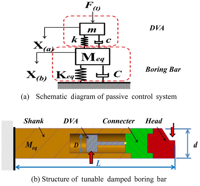
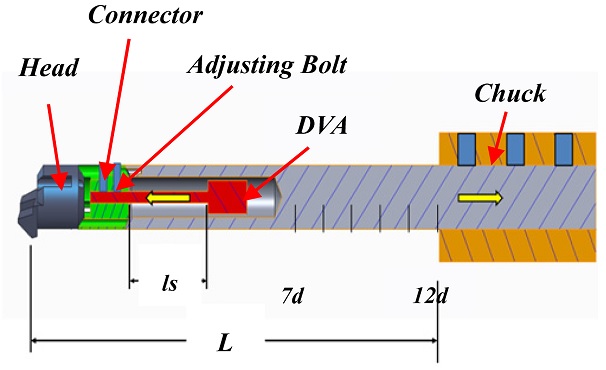
The schematic of the dynamic model of the proposed passive tunable boring bar is depicted in
Fig. 1(a) and its structure is shown in
Fig. 1(b). In the
Fig. 1,
F, X
(a), and X
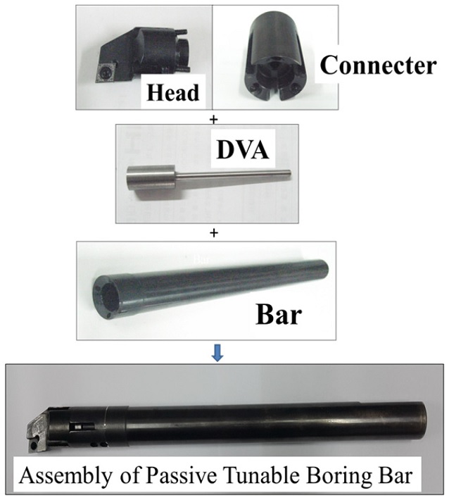
(b) denote the external force, and the absolute displacements of the DVA and the boring bar, respectively. The body consists of a shank, connector, and head. The shank has an inner hole to accommodate the DVA, the connector fixes the DVA, and the head combines the inserted blade. The DVA is of an adjustable spring cantilever form. Its function is to absorb the vibration energy of the structure’s movement by creating a resistant force in the opposite direction to the excitation force. This can be achieved by adjusting the DVA spring length. The vibration frequency varies with the overhang.
Fig. 1Concept model of tunable damped boring bar
2.2 Analysis Using Euler’s Beam Theory
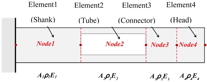
Fig. 2 depicts the computation flow chart for modeling a tunable damped boring bar based on Euler’s beam theory. The bar has multiple cross sections, as shown in
Fig. 3. The lengths of the head, connector, tube, and shank are
l4,
l3,
l2, and
l1, respectively.
Fig. 2Flow chart of theoretical analysis
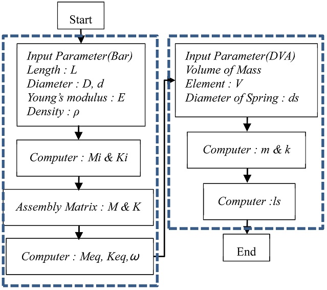
Fig. 3Structure of tunable boring bar body
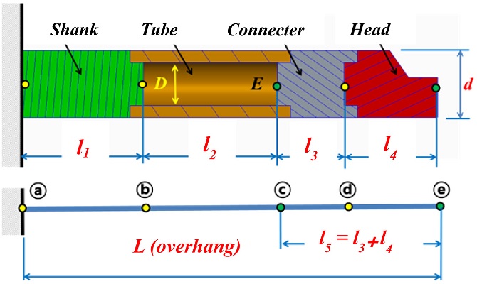
The insert tip is assembled into the head section. The connector adjusts the position of the DVA in the tube section.
l5 is the distance between points ⓒ and ⓔ. The elasticity “
E” at point ⓒ is an important design parameter required to determine the effective mass and stiffness of the DVA.
7
The body of the tunable damped boring bar has multiple cross sections consisting of several beam elements. In this study the body was modeled with 5 nodes and 4 beam elements as in
Fig. 4 to solve the mass and rigidity of the tunable damped boring bar body.
Fig. 4Element of tunable damping boring bar body

Equation matrices in terms of the mass and stiffness of each element are solved and combined to produce those of the body. The matrices are expressed in
Eqs. (1) and
(2).
In the equations, “E” is the elasticity coefficient, ρ is the density, and “l ” is the length of the beam element.
The subscript i denotes the index of each beam element (1 = shank, 2 = tube, 3 = connector, 4 = head). To simplify the analysis, the matrices of
Eqs. (1) and
(2) can be divided into four sections as shown in
Eqs. (3) and
(4).
8-10
If the displacement and rotation angle of the boring bar are assumed to be 0, which is the case for the boundary conditions of a cantilever,
8-10 Eqs. (7) and
(8) are obtained.
Where [
M] is the mass matrix
Eq. (7), [
C] is the attenuation matrix, [
K] is the stiffness matrix
Eq. (8), {
x} is the displacement vector, and {
f} is the force vector. If the force vector and attenuation matrix are assumed to be 0, the characteristic can be expressed as.
8-10
Then, the mode can be analyzed from the solution of the characteristic equation.
λ obtained in the process of solving
Eq. (10) is called the eigenvalue. Multiplying [
M]
-1, which is the transposed matrix of [
M], on each side of
Eq. (10) produces
Where [I] is the unit vector and [D] is the dynamic matrix defined as
For the solution of {x} to be valid, the characteristic matrix must become 0 and is expressed as
Eq. (13) can be developed into an n-dimensional polynomial. As
λ =
ω2 in the characteristic or oscillation equation, the mode configuration and eigenvector {
x} can be obtained through
λ.
ω2 is referred to as the natural frequency of the oscillation system, and the matrix consisting of the eigenvectors is referred to as the modal matrix appearing in
Eq. (14).
Where ϕji is the mode matrix, j is the nodal point, and i is the dimension number of the mode. Hence, the equivalent mass and stiffness of the nodal point can be obtained as
In the analysis, the outer radius of the body shank, d, is 25 mm, and the lengths of the overhangs are entered sequentially into the computation as values from 7d to 12d in intervals of 1d.
Table 1Input parameter of tunable boring bar body
Table 1
|
Parameter Name |
Quantity |
|
Head length (l4) |
40(mm) |
|
Connector length ( l3) |
28(mm) |
|
Tube length (l2) |
100(mm) |
|
Vibration output position (l5) |
68(mm) |
|
Boring bar’s diameter (d) |
25(mm) |
|
Boring bar’s tube inner dia. (D) |
16(mm) |
|
Boring bar’s young’s modulus (E) |
2E+11(pa) |
|
Boring bar’s density (ρ) |
7850(Kg/m3) |
|
Boring bar’s material |
SCM440 |
|
Boring bar’s hardness |
33~38(HRC) |
|
Boring Bar overhang(L ) |
7d ~ 12d(mm) |
Table 2Theoretical analysis result of tunable damping boring bar body with euler beam theory
Table 2
|
Overhang of boring bar : L (mm) |
Frequency (Hz) |
|
7d (175mm) |
538.26 |
|
8d (200mm) |
431.21 |
|
9d (225mm) |
351.31 |
|
10d (250mm) |
290.77 |
|
11d (275mm) |
244.06 |
|
12d (300mm) |
207.40 |
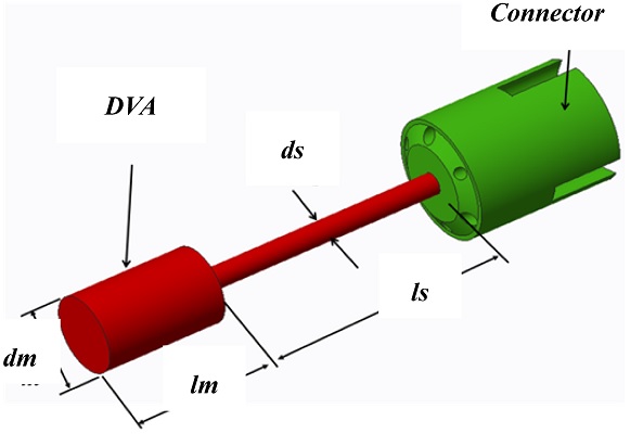
2.3 Design of a DVA Based on Boring Bar Overhang
The DVA consisting of a single-spring.
15structure was designed based on a tunable bar body. The mass and stiffness for the DVA are expressed in the following
Eqs. (17) and
(18).
Where M
eq and K
eq are the equivalent mass and stiffness of the body. The DVA is a cylinder of radius
ds suitable for adjusting and fixing
ls.
dm and
ds in
Table 3 are set as constants considering the spaces of the inner diameter
D (16 mm) and
l2 (100 mm) of the bar. The length of the DVA,
lm, is obtained in
Eq. (19).
Fig. 5Analysis model of DVA

Table 3Input parameter of DVA
Table 3
|
Parameter Name |
Quantity |
|
Mass’s Diameter (dm) |
14(mm) |
|
Spring’s Diameter (ds) |
5(mm) |
|
Young’s modulus (E) |
1.4312E+11(pa) |
|
Density (ρ) |
7850(Kg/m3) |
|
Material |
SCM440 |
|
Hardness |
55~60(HRC) |
Since the second cross-sectional moment
Id and stiffness
kd of the DVA are obtained in
Eqs. (20) and
(21), the tunable spring length of the DVA,
ls, and the frequency can be solved in
Eq. (22).
The calculated results for
ls for a DVA suitable for each overhang are shown in
Table 4.
Table 4Tuning result of spring length (ls) on DVA
Table 4
|
Overhang of boring bar : L (mm) |
ls (mm)of DVA |
|
7d (175mm) |
15 |
|
8d (200mm) |
21 |
|
9d (225mm) |
26 |
|
10d (250mm) |
33 |
|
11d (275mm) |
38 |
|
12d (300mm) |
43 |
3. Simulation Using the CAE Program
3.1 CAE Simulation of a Tunable Boring Bar Body
In the simulation of a complex structure, which is basically a continuous system, an approximation is needed to convert it into a system with multiple degrees of freedom. For this purpose, the finite element approach using the CAE program is beneficial.
In this study, the CAE program was used. The bar body was modeled as shown in
Fig. 6.
Fig. 6Analysis model of body on CAE program

The body consisting of the head, connector, and shank was assembled into a chuck. The simulation was performed with changing overhangs. The input variables are listed in
Table 1.
The overhangs were adjusted from 7
d to 12
d in 1
d intervals as shown in
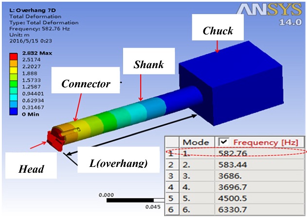
Fig. 7. Six modes were analyzed, but only the results of the first mode are presented in this paper because this mode represents the principal force
11,12 most closely related to the vibration. The results are summarized in
Table 5.
Fig. 71th Mode analysis result of overhang for body
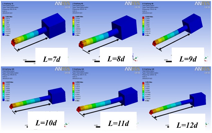
Table 5Natural frequencies of boring bar body on CAE
Table 5
|
Overhang of boring bar : L (mm) |
Frequency (Hz) |
|
7d (175mm) |
582.76 |
|
8d (200mm) |
465.91 |
|
9d (225mm) |
378.31 |
|
10d (250mm) |
309.25 |
|
11d (275mm) |
260.71 |
|
12d (300mm) |
220.81 |
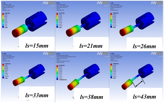
3.2 CAE Simulation of DVA
The CAE simulation model of the DVA is shown in
Fig. 8. The DVA is attached to the connector, which adjusts and fixes the spring length
ls of the DVA. The parameters in
Tables 3 and
4 were applied for the DVA analysis. The simulation was conducted with regard to the first-mode natural frequencies of the spring lengths,
ls, alone, and the results are presented in
Table 6.
Fig. 8Analysis model of DVA on CAE program
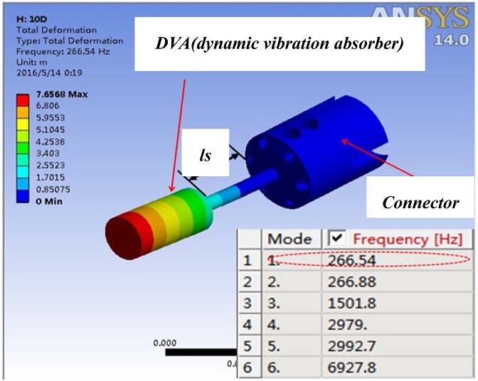
Fig. 91 th Mode analysis result of DVA

Table 6Natural frequencies of spring length (DVA) on CAE
Table 6
|
Spring Length ls (mm) |
Frequency (Hz) |
|
15 (mm) |
585.13 |
|
21 (mm) |
407.51 |
|
26 (mm) |
343.83 |
|
33 (mm) |
266.54 |
|
38 (mm) |
221.14 |
|
43 (mm) |
197.16 |
4. Test of a Passive Tunable Damped Boring Bar
4.1 The Manufacture of Design Model
The design model of a tunable damped boring bar is shown in
Figs. 10 and
11 is a photograph of each manufactured part and assembled state. The experimental method is to apply the impact hammer and analyze the signal by applying the impact of the boring bar.
Fig. 10Design model of tunable damped boring bar
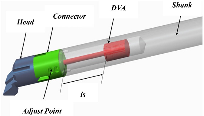
Fig. 11Photo of passive tunable damped boring bar

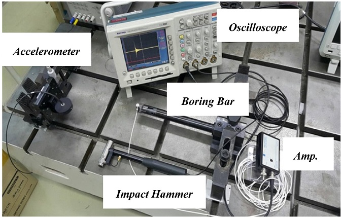
4.2 Impulse Excitation Test of Boring Bar Body
An impulse excitation was applied to the test bar to determine the natural frequency of the body. As
Fig. 12 indicates, the test was conducted with the boring bar attached to the chuck but without the DVA. The natural frequency was measured under the same conditions used in the CAE simulation in section 3.1. Test results are presented in
Fig. 13 and
Table 7.
Fig. 12Photo of experiment setup for boring bar body

Fig. 13Natural frequency of overhang 7d-12d
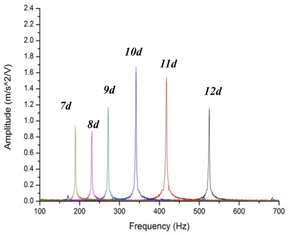
Table 7Natural frequencies of boring bar body on experiment
Table 7
|
Overhang of boring bar : L (mm) |
Frequency (Hz) |
|
7d (175mm) |
520 |
|
8d (200mm) |
420 |
|
9d (225mm) |
340 |
|
10d (250mm) |
270 |
|
11d (275mm) |
230 |
|
12d (300mm) |
195 |
4.3 Impulse Excitation Test of DVA
In this test,
ls was adjusted using the results in
Table 4. The natural frequency was measured by a non-contact optic fiber sensor with a resolution of 0.28
μm, as shown in
Fig. 14. The measured values are presented in
Table 8.
Fig. 14Photo of experiment setup for DVA
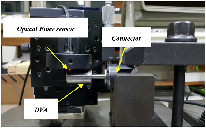
Table 8Natural frequency of DVA on experiment
Table 8
|
Spring Length ls (mm) |
Frequency (Hz) |
|
15 (mm) |
530 |
|
21 (mm) |
415 |
|
26 (mm) |
325 |
|
33 (mm) |
265 |
|
38 (mm) |
225 |
|
43 (mm) |
190 |
4.4 Comparison of Analysis and Test Results
The results of the theoretical analysis in
Table 2 based on Euler’s beam theory, the simulation in
Table 8 using the CAE program, are all compared in
Table 9.
Table 9Comparison between frequency domain of theoretical review and experimental result in boring bar body
Table 9
|
Boring bar overhang L (mm) |
Natural frequency of boring bar body |
|
Theoretical analysis (Hz) |
CAE analysis (Hz) |
Experiment (Hz) |
|
7d (175) |
538.26 |
582.76 |
520 |
|
8d (200) |
431.21 |
465.91 |
420 |
|
9d (225) |
351.31 |
378.31 |
340 |
|
10d (250) |
290.77 |
309.25 |
270 |
|
11d (275) |
244.06 |
260.71 |
230 |
|
12d (300) |
207.40 |
220.81 |
195 |
The differences in natural frequencies between the theoretical analysis and the CAE simulation for the various overhangs are approximately 7% while those between the theoretical analysis and test results are approximately 6%, as shown in
Table 9.
Similarly, the difference in the obtained natural frequencies between the theoretical analysis and the CAE simulation with variation of the spring length of the DVA,
ls, are approximately 6% while those between the theoretical analysis and test results are approximately 8%, as shown in
Table 10. Therefore, it can be seen that the boring bar design is possible through the theoretical analysis presented in this paper.
Table 10Comparison between natural frequencies of CAE and theoretical review in ls for DVA
Table 10
|
Spring length ls (mm) |
Natural frequency of DVA (ls) |
|
Theoretical analysis (Hz) |
CAE analysis (Hz) |
Experiment (Hz) |
|
15 |
538.26 |
585.13 |
530 |
|
21 |
431.21 |
407.51 |
415 |
|
26 |
351.31 |
343.83 |
325 |
|
33 |
290.77 |
266.54 |
265 |
|
38 |
244.06 |
221.14 |
225 |
|
43 |
207.40 |
197.16 |
190 |
Fig. 15Adjusting setup for tunable damped boring bar
4.5 Impulse Excitation test of Damping Capability
Together with the results in section 4.4, the DVA was inserted inside the tunable damped boring bar body and an impulse excitation test was applied as shown in
Fig. 12. The overhang was adjusted to the benchmarks by adjusting the spring length
ls inside the body as in
Table 2.
An impact hammer provided an impact at the end tip of the boring bar. An oscilloscope was used to measure the absorption capability of the DVA.
The test results are the same as those of the passive control simulation.
8 Part of the test results are shown in
Fig. 16.
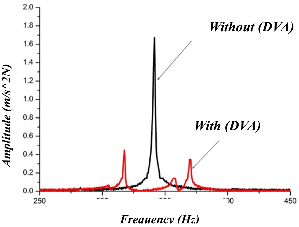
Fig. 16FFT analysis of passive tunable damped boring bar for overhang 9d

Table 11 indicates that the damping effect reaches a maximum of 73.8% at position 9
d (225 mm) and more than 50% at all positions.
Table 11Comparison between impulse test of general system and passive system in tunable damped boring bar
Table 11
|
Tunable damped boring bar overhang L (mm) |
Frequency Domain |
Damping rate (%) |
|
Amplitude without DVA (m/N) |
Amplitude with DVA (m/N) |
|
7d (175) |
1.18 |
0.55 |
53.4% |
|
8d (200) |
1.55 |
0.41 |
73.5% |
|
9d (225) |
1.64 |
0.43 |
73.8% |
|
10d (250) |
1.19 |
0.59 |
50.4% |
|
11d (275) |
0.89 |
0.42 |
52.8% |
|
12d (300) |
0.94 |
0.35 |
62.7% |
It is indicated that the proposed tunable damped boring bar can control the vibration of the internal DVA by adjusting the overhang, hence offering a better damping effect than the existing passive boring bar design.
The proposed design can also control a wider frequency band such as that generated from various overhangs, while the existing design can damp oscillations within only a limited frequency band. More applications can be anticipated with future work.
4.6 Cutting Test of Tunable Damped Boring Bar
Based on the results in
section 4.5, Cutting test was carried out for tunable damped boring bar as shown in
Fig. 17. Experimental methods for cutting were performed under the same conditions as
Tables 12 and
13 shows the equipment, materials and cutting conditions.
Fig. 17Photo of experiment setup for cutting process
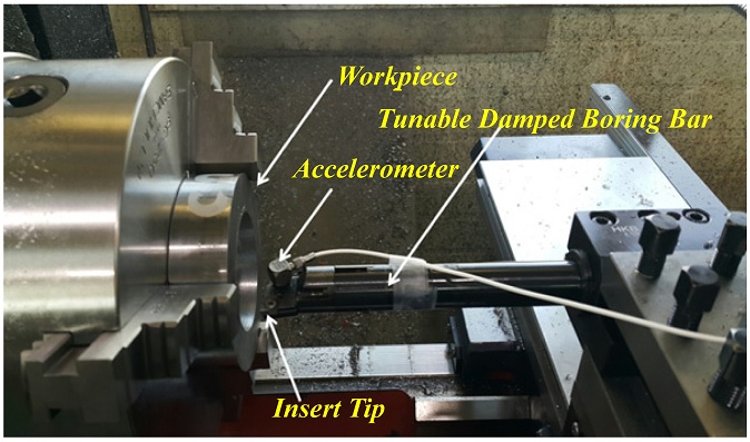
Table 12Tunable condition of tunable damped boring bar on cutting process
Table 12
|
Tunable damped boring bar overhang L (mm) |
Spring length of DVA ls (mm) |
|
7d (175) |
15 |
|
9d (225) |
26 |
|
11d (275) |
38 |
Table 13Cutting condition of boring process
Table 13
|
Process condition |
Quantity |
|
Cutting speed (V) |
80(m/min) |
|
Feed (f) |
0.132(mm/rev) |
|
Depth (mm) |
0.5(mm) |
|
Workpiece (material) |
SM45C |
|
Workpiece size (Tube type) |
Inside 60(mm) |
|
Outside 100(mm) |
|
Machine Type |
Lathe (HL-380) |
|
Tool of insert tip |
CCMT 09T304 |
Fig. 18Comparison between steel bar and tunable damped bar in frequency domain
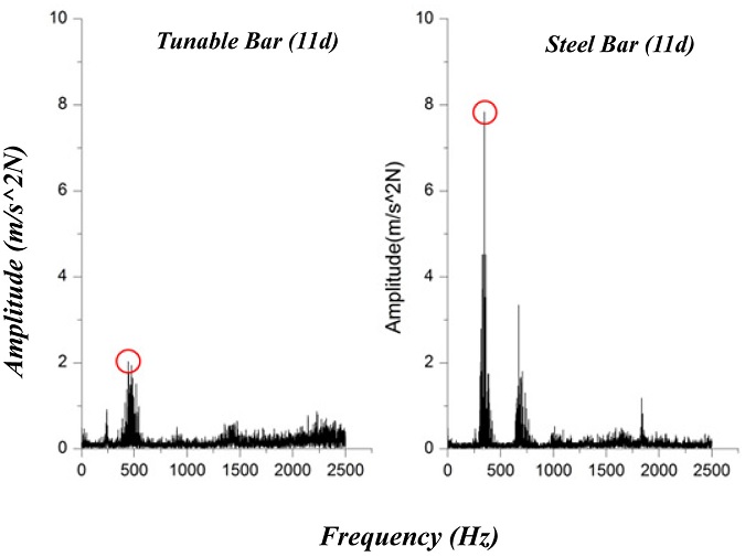
For the cutting test method, the overhang (
L) of the boring bar was adjusted to the benchmarks by adjusted the spring length (
ls) of DVA inside the boring bar as
Table 12.
In addition, the vibration frequency and surface roughness of the workpiece were measured to compare the performance of the steel boring bar and a tunable damped boring bar. The cutting test results showed that the vibration frequency amplitude of the tunable damped boring bar was reduced.
The improvement effects are shown in
Table 14.
Table 14Comparison between cutting process of steel bar and tunable damped boring bar on frequency domain
Table 14
|
Boring bar overhang L (mm) |
Frequency domain |
Damping rate (%) |
|
Amplitude of steel bar (m/N) |
Amplitude of tunable bar (m/N) |
|
7d (175) |
6.52 |
4.45 |
31.7% |
|
9d (225) |
11.28 |
3.25 |
71.2% |
|
11d (275) |
7.98 |
2.17 |
72.8% |
Table 14 indicates that the damping effect of tunable damped boring bar reaches a maximum of 72.8% at position 11
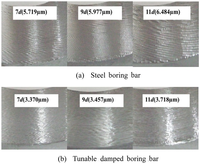
d (275 mm) and more than 30% at all positions. Based on the result of cutting test, the roughness of the workpiece was measured. The measurement results are shown in
Fig. 19.
Fig. 19Comparison between steel bar and tunable damped bar in surface roughness (Ra)

The measurement of surface roughness was carried out in accordance with ISO1997.
Fig. 19 indicates that the improvement effect of surface roughness reaches a maximum of 50.9% at position 11
d (275 mm) and more than 40% at all positions.
5. Conclusion
A new type of tunable damped boring bar has been proposed to suppress vibrations occurring in the boring process. The dynamic characteristics of its body were modeled using Euler’s beam theory. The analysis results were supported by comparison with the results of CAE simulation and experimental tests. The following conclusions are drawn.
(1) The model showed less than 7% error compared to the predictions of simulations, assuring its validity.
(2) Based on the analysis, a new DVA design was proposed. Additionally, the spring length, which is the tuning parameter, ls, was determined. The designed length showed approximately 8% inaccuracy compared with measurements.
(3) Based on the analysis and simulation, a tunable damped boring bar was manufactured and impulse excitation tests were performed. Adjustment of the DVA spring length for the given overhang was able to tune the frequency accordingly.
(4) The tuning test between 7d to 12d at 1d intervals showed that vibration was attenuated by more than 50% over the entire range, with a maximum effect of 73.8% at 9d.
(5) Through the cutting experiment, general steel boring bar and tunable damped boring bar was compared. And the cutting test between 7d to 11d at 2d intervals showed that vibration amplitude was attenuated by more than 30% ~ 70% over the entire range, with a maximum effect of 72.8% at 11d.
(6) Based on the cutting test, the surface roughness of workpiece indicated that improvement effect was confirmed a maximum of 50.9% at position 11d and more than 50% at all positons.
(7) The cutting test of tunable damped boring bar between 7d to 11d at 2d intervals showed that surface roughness was constant as a micro value and the standard deviation was 0.181μm. Therefore, the effectiveness of tunable damped boring bar design was verified.
The proposed passive damped boring bar offers better frequency-damping capability by adjusting the length of the inserted spring ls compared with existing boring bars, which respond only to limited overhangs. Improvement in the proposed design elements and the addition of external attenuation elements could produce further advancement in future research.
ACKNOWLEDGMENTS
This work supported by Research Program supported by Chung-Nam National University academic policy of 2015.
REFERENCES
- 1.
Moradi, H., Bakhtiari-Nejad, F., and Movahhedy, M., “Tuneable Vibration Absorber Design to Suppress Vibrations: An Application in Boring Manufacturing Process,” Journal of Sound and Vibration, Vol. 318, No. 1, pp. 93-108, 2008.
10.1016/j.jsv.2008.04.001
- 2.
New, R. and Au, Y., “Chatter-Proof” Overhang Boring Bars-Stability Criteria and Design Procedure for a New Type of Damped Boring Bar,” Journal of Mechanical Design, Vol. 102, No. 3, pp. 611-618, 1980.
10.1115/1.3254793
- 3.
Tanaka, H., Obata, F., Matsubara, T., and Mizumoto, H., “Active Chatter Suppression of Slender Boring Bar Using Piezoelectric Actuators,” JSME International Journal, Vol. 37, No. 3, pp. 601-606, 1994.
10.1299/jsmec1993.37.601
- 4.
Hwang, H. Y. and Kim, J. K., “Design and Manufacture of a Carbon Fiber Epoxy Rotating Boring Bar,” Composite Structures, Vol. 60, No. 1, pp. 115-124, 2003.
10.1016/S0263-8223(02)00287-8
- 5.
Viana, F. A. C., Kotinda, G. I., Rade, D. A., and Steffen, V., “Tuning Dynamic Vibration Absorbers by Using Ant Colony Optimization,” Computers & Structures, Vol. 86, No. 13, pp. 1539-1549, 2008.
10.1016/j.compstruc.2007.05.009
- 6.
Szuba, P., Zou, Q., Barber, G., and Yang, L., “Optimization of Hollow Cantilevered Boring Bar Stiffness,” Machining Science and Technology, Vol. 9, No. 3, pp. 325-343, 2005.
10.1080/10910340500196504
- 7.
Guo, Y. Y., Park, J. K., Hong, J. H., and Song, D. S., “Development of a GUI Program for the Design of a Vibration Control Boring Bar with a Tube-Type Structure,” Journal of the Korean Society, Vol. 25, No. 4, pp. 295-300, 2016.
10.7735/ksmte.2016.25.4.295
- 8.
Palm, W. J., “Mechanical Vibration,” John Wiley and Sons, 2006.
- 9.
- 10.
Krysinski, T. and Malburet, F., “Mechanical Vibrations Active and Passive Control,” John Wiley and Sons, pp. 175-303, 2007.
10.1002/9780470612477
- 11.
Altintas, Y., “Manufacturing Automation: Metal Cutting Mechanics, Machine Tool Vibrations, and CNC Design,” Cambridge University Press, pp. 15-187, 2012.
- 12.
Koenigsberger, F. and Tlusty, J., “Machine Tool Structures,” Elsevier, 2016.
- 13.
Vonflotow, A. H., Beard, A., and Bailey, D., “Adaptive Tuned Vibration Absorbers: Tuning Laws, Tracking Agility, Sizing, and Physical Implementations” Proc. of the 1994 National Conference on Noise Control Engineering, pp. 437-454, 1994.
- 14.
Mei, C., “Active Regenerative Chatter Suppression during Boring Manufacturing Process,” Robotics and Computer-Integrated Manufacturing, Vol. 21, No. 2, pp. 153-158, 2005.
10.1016/j.rcim.2004.07.011
- 15.
Wu, J.-J., “Study on the Inertia Effect of Helical Spring of the Absorber on Suppressing the Dynamic Responses of a Beam Subjected to a Moving Load,” Journal of Sound and Vibration, Vol. 297, No. 3, pp. 981-999, 2006.
10.1016/j.jsv.2006.05.011