ABSTRACT
FEM (Finite Element Method)-based numerical analysis model, which is known as CAE (Computer Aided Engineering) technology, has been adopted for the visual/mechanical analysis of machining process. The essential models for the FEM analytical model are the plasticity model of workpieces, friction model, and wear rate model. Usually, the outputs of the FEM analytical model are the cutting force, the cutting temperature, and chip formation. Based on these outputs, the machining performance can be virtually evaluated without experiments. Nowadays, there are emerging machining technologies, such as cryogenic assisted machining and CFRP machining. Therefore, FEM technique can be one of the good candidate to virtually evaluate emerging developed machining technologies.
-
KEYWORDS: Machining, Modeling, Finite element method, Computer aided engineering
-
KEYWORDS: 기계 가공, 모델링, 유한요소해석, 컴퓨터 응용 해석
1. 서론
기계 가공 기술은 지난 수세기에 걸쳐, 산업 제품을 생산하기 위한 하나의 수단으로써 사용되고 현재에도 꾸준히 발전하고 있다. 기계 가공은 회전하는 공구 혹은 재료를 이용하여 하나의 큰 덩어리를 쪼개고 재료를 제거하는 과정을 통해 형상을 만들어내는 일련의 과정을 의미한다. 일반적인 기계 가공은 크게 선삭(Turning), 밀링(Milling), 드릴링(Drilling), 쉐이핑(Shaping), 브로칭(Broaching), 연삭(Grinding) 등으로 나눌 수 있다.
1
기계 가공에 적용되는 재료는 기존 철강 재질을 기반으로 비철 소재, 특수 합금 소재 등으로 다양하게 발전하고 있으며, 현재는 3차원 프린팅을 통해 제작한 소재까지 적용되고 있다. 소재에 대한 지속적인 발전과 함께 산업에 적용하기 위한 기계 가공 공정에 대한 연구 역시 요구되고 있으며, 공구 수명 증가, 고속 가공, 초정밀 가공 등 기존 공정을 뛰어 넘기 위한 기술이 개발되고 있다. 새롭게 개발되고 산업에 적용하기 위해서 기계 가공에 대한 모델링 개발이 필수적이다. 공정 모델링은 가공 중 발생하는 신소재에 대한 소성학적 해석 및 물성 거동, 절삭력/절삭 온도 분석을 통한 품질 예측, 공정 조건에 대한 최적화를 위해 필요하다.
2
기계 가공 모델링은 실험 기반 모델(Empirical Model),
3-5 해석 기반 모델(Analytical model),
2,6-8 수치해석 기반 모델(Numerical model)로
9-11 크게 3가지로 나눌 수 있다. 실험 기반 모델은 실험을 통해 측정한 절삭력을 회귀분석을 통해 계산된 계수(Specific Cutting Coefficient)를 이용하여 다른 가공 조건의 절삭력을 예측하는 방식이다. 이 모델은, 절삭력이 칩 면적에 비율적으로 변화한다.
2 또한, 실험 조건, 재료 등에 따라 많은 실험 데이터를 통해 통계학적으로 접근하기 때문에 대량의 실험이 요구되고 시간 및 예산에 대한 소요가 크다.
해석 기반 모델은 가공 메커니즘에 대한 수학적 모델링을 통해 가공 공정 중 발생하는 절삭력/절삭 온도 등에 대해 해석이 가능하다. 가공 중 발생하는 재료 소성을 미끄럼 선장 이론(Slip-Line Theory)을
8 이용하여 해석을 할 수 있다. 해석 기반 모델은 빠른 시간 내에 결과 계산이 가능하다는 장점이 있지만, 모델을 개발하는데 상당한 시간 소요가 필요하다.
수치해석 모델은 유한요소해석법(Finite Element Method, FEM)을 기반으로 대상 물체를 컴퓨터 상에서 가공 공정과 동일하게 해석을 진행할 수 있다. 시각적 결과와 해석적 결과를 동시에 예측이 가능하기 때문에, 기존 해석 모델과 실험 모델에 대한 단점을 보완 할 수 있다. FEM 기반 수치해석 모델은 또한 칩 생성과 관련하여 가공 공정과 동일하게 해석이 가능하기 때문에 칩 말림 현상 등 산업 현장에서 발생 가능한 문제에 대해서 예측이 가능하다는 장점이 있다. 해석 시간은 다른 모델 기법에 비해 다소 길다는 단점이 있으나 절삭력,
12,13 절삭 온도,
14,15 가공 표면,
16,17 공구 마모,
18,19 등 많은 해석 결과를 제공 가능하다.
본 논문에서는 가공 CAE 기술 중 FEM 기반 수치해석 모델에 대한 전반적인 연구 동향에 대해서 정리하였고, 향후 방향에 대해서 제시하였다. 2장에서는 FEM 모델 해석 기법 알고리즘에 대해서 장단점을 비교하고 고려해야할 요인에 대해서 나타내었다. 또한, FEM 모델을 수립하기 위해 요구되는 재료 소성 모델 및 칩 생성을 위한 모델 물성치, 마찰 모델에 대해서 나타내었다. 3장에서는 FEM 모델을 통해 예측 가능한 주요 결과로써 절삭력, 절삭온도, 칩 생성에 대하여 정리하였다. 4장에서는 최신 가공 공정 중 극저온 공정과 탄소 복합체 가공 공정에 대한 FEM 모델 수립 시 고려해야할 사항에 대해서 정리하였다. 5장에서는 FEM 모델에 대한 결론 및 향후 연구 방향에 대해서 논의하였다.
2. FEM 모델 수립 시 고려해야할 사항
2.1 해석 알고리즘
가공 공정에 대한 수치해석을 수행하기 위한 알고리즘은 대표적으로 라그랑지안(Lagrangian)과
2,10 오일러(Euler)
2 방식이 있다. 라그랑지안은 공구가 재료에 일정 속도로 접촉했을 때, 소성에 대한 해석을 각각 모든 요소망을 추적하면서 계산하는 방식이다. 반면 오일러 방식은 관찰하고자 하는 영역은 고정되어 공구에 의한 재료 소성 변화를 상대적으로 계산하는 방식으로 유체 해석에 가장 많이 쓰이는 계산 방식이다. 오일러 방식은 기계 가공 공정의 정상 상태를 가정하여 해석을 진행하는 방식이기 때문에 정확도가 떨어진다는 단점이 있다.
2 라그랑지안 방식의 경우 공구에 의해 심한 요소 변형(Mesh Distortion) 및 시간 간격(Time Step)
20 등의 문제로 인해 수렴이 안되는 문제를 지니지만, 칩 생성 등 시각적 해석이 가능하기 때문에 가장 실제 가공 공정과 유사하게 해석이 가능하다. 라그랑지안 방식에 Remeshing 기법을
21,22 더해 요소 변형에 대한 문제를 해결한 방식도 있다. 라그랑지안 방식은 칩 생성 해석을 위해 기준(Chip Separation Criteria)을 정해줘야 해석이 가능 하다.
2
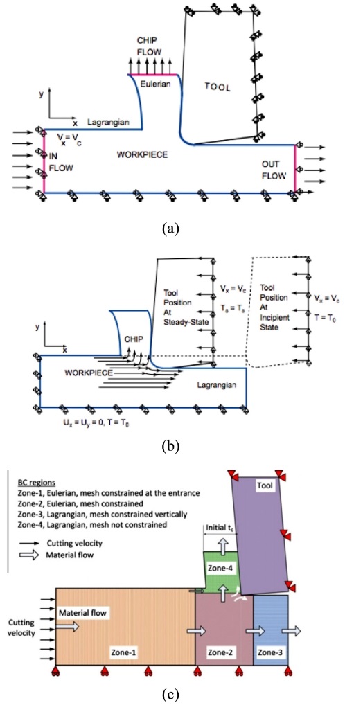
라그랑지안과 오일러의 장점을 결합한 알고리즘으로 임의 라그랑지-오일러 방식(Arbitrary Lagrangian-Eulerian, ALE)도
9,23-25 존재한다. ALE (
Fig. 1)은 라그랑지 알고리즘에서 발생할 수 있는 요소 변형에 의해 발생할 수 있는 수렴 문제를 어느정도 방지가 가능하다. 매 Step 마다 요소 및 Mesh를 재배열을 하며 전체 요소망의 개수는 변하지 않는다. 시간이 추가 되어 전체 계산 시간은 증가할 수 있다는 단점이 존재한다. ALE는 라그랑지안 방식만 적용한 모델과 비교하여 칩 생성을 위한 기준을 따로 정해줄 필요가 없다.
2
Fig. 1FE model for ALE10 with : (a) Eulerian-Lagrangian (b) pure Lagrangian and (c) CEL model setup schematic26 (Adapted from Refs. 10 and 26 on the basis of open access)

기계 가공 공정은 기본적으로 대변형(Large Deformation)을 해석 하기 때문에, 앞서 언급한 알고리즘으로도 해석을 진행하기 어려울 경우가 있다. Coupled Eulerian-Lagrangian (CEL)
11,26 방식을 적용 할 경우 상대적으로 좀더 안정적인 계산 결과를 얻을 수 있다. CEL (
Fig. 1)는 일부를 오일러로 적용하고, 칩 생성과 같이 대변형 계산이 필요한 부분에 라그랑지안을 적용하는 방식이다. 모델링을 하기에 다소 복잡하기는 하지만 다른 방식에 비해서 계산 안정성이 높고, 칩 생성에 대한 해석이 가능하다.
가공 중 발생하는 칩 생성은 일반적인 가공 공정에서는 연속칩(Continues Chip)이 발생하기 때문에 시간과 경제성을 고려하여 ALE, CEL 방식으로의 접근이 필요하다. 그러나, 고경도강 가공 및 특수 합금 가공과 같이 재료의 물성치가 상대적으로 높고 톱니형 칩(Serrated Chip) 또는 불연속 칩(Discontinues Chip)에 대한 해석이 요구 될 경우 일반 라그랑지안 기법과 칩 생성 기준을 이용하여 해석을 진행하여야 한다.
2.2 재료 소성 모델
기계 가공 중 재료는 소성 변형(Plastic Deformation)과 칩 생성(Chip Formation)이 발생한다. 소성 변형에 의해 절삭력과 절삭온도가 증가하고, 경계조건 및 환경이 변하기 때문에 소성 거동이 변화한다. 또한, 가공 중 발생하는 재료 변형(Strain)은 기초 인장 실험을 기준으로100-700% 이상으로 높으며, 변형율(Strain Rate) 범위는 기존 10
-3-10
-1 sec
-1에서 10
3-10
5 sec
-1으로 높은 범위에 속한다.
1,2,27 이러한 소성 변형 및 범위를 나타내기 위해 꾸준히 재료에 대한 수식 모델(Constitutive Model of Workpiece)이 개발되어오고 있다.
기계 가공 해석 시 가장 폭 넓게 사용되는 모델로써1983년에 발표된 Johnson-Cook (JC) Constitutive Model이
28 가장 대표적이다.
식(1)에 는 JC 모델이 나타나 있으며, 3가지 요인에 대해서 고려할 수 있다.
JC 모델은(ε¯, Strain), 변형률(ε¯˙, Strain-Rate [s-1]), 온도(Temperature)에 대해서 고려하여 재료의 소성 거동을 유동 응력(σ¯flow-stress, Flow Stress)으로 표현할 수 있다. JC 모델은 총 5가지 변수에 의해 결정된다. A는 일반 상온 온도(약 25oC)에서의 초기 항복 응력(Initial Yield Stress, [MPa])을 의미며, B는 변형 경화율(Hardening Modulus, [MPa]), n은 변형 경화 계수(Hardening Coefficient, [Unitless])를 의미한다. A, B, n으로 재료의 외력에 대한 변형을 모사할 수 있다. 변형률에 대한 수식은 변형률속도 민감도(C, Strain Rate Sensitivity, [Unitless])에 의해 결정된다. ε¯˙0(Reference Strain-Rate [s-1])는 기준이 되는 변형률 속도를 의미하는데 일반적으로 0.1-1 사이로 결정하여 사용한다. 온도과 관련한 수식의 경우 Tm은 재료의 녹는점(Melting Temperature of Workpiece)을 의미하고, T0는 초기 온도로써 약 25oC를 기준으로 사용한다. JC 모델은 가공 중 발생하는 온도, 변형, 변형률에 대한 고려가 가능하기 때문에 대부분의 기계 가공 해석 시 가장 많이 사용되고 있다.
JC 모델을 기반으로 칩 생성(Chip Formation)에 대한 해석을 진행하기 위해서 파단 기준을 정해주어야 한다. 파단 기준을 정하는 모델은 크게 2가지 방법이 있으며, Damage Model을
29-32 적용하는 방법과 Flow-Softening
33 현상 반영 모델을 적용하는 방법이 있다.
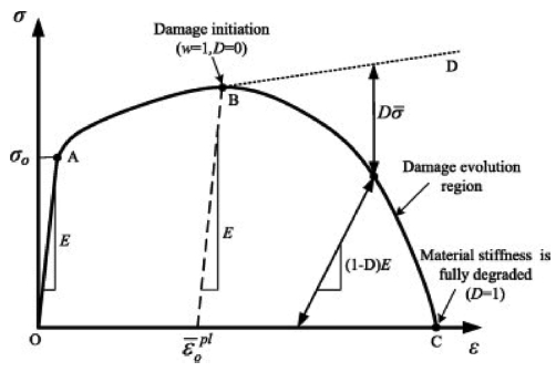
Fig. 2에는 재료에 대한 Damage 선도가 나타나있다. O에서 A까지는 재료에 대한 탄성 영역이며, A에서 B 영역은 재료의 소성 영역을 의미한다. B 지점은 최초 파단이 시작 지점으로 칩이 공구에 의해 분리되는 지점을 의미한다. B에서 C 지점(
εf)까지 재료의 거동을 Damage Model로 표현한다.
Fig. 2Stress-Strain response of material damage evolution29 (Adapted from Ref. 29 on the basis of open access)
Johnson-Cook (JC) Damage Model은
Fig. 2에 대해서 다음
식(2)와 같이 표현할 수 있다. JC Damage Model은 JC 소성 모델과 유사하게 Strain 영역, Strain-Rate 영역, Temperature 영역에 대해 고려할 수 있다. 파단 변형(
εf, Failure Strain)은 5개의 계수(
C1~
C5), 정수압(
P, Hydrostatic Pressure)에 의해 결정된다.
JC Damage Model외에 Brozzo Damage Model,
30 Cockroft and Latham Damage model,
32 McClintock Damage Model
31등이 있다.
Flow-Softening을 반영한 모델의 경우 Damage Model이 추가로 요구되지 않으며, Initiation Point 이후의 유동 응력 거동을 모두 표현할 수 있다. 대부분의 경우 JC 소성 모델을 기반으로 수정하여 각 상황에 맞도록 조정한 경우가 많으며 현재까지 연구가 활발히 되고 있다. 2010년에 Sima et al.
33는 JC 모델을 수정하여 온도와 변형 연화(Strain Softening)를 반영한 모델을 발표하였다.
식(3)에서
D,
p,
r,
s는 온도 증가로 인해 감소하는 유동 응력을 반영할 수 있다.
절삭 가공 시 발생하는 온도에 의해 금속 미세 조직 상변화에 대한 고려가 필요하기 때문에 물리 기반 모델(Physical-Based Constitutive Model)도
33,34 개발되었다. Denguir et al.
34은 기존 JC 수식에 미세조직 상변화 효과(Microstructural Transformation Effect), 응력 상태 효과(State of Stress Effect)를 반영한 새로운 수식을 제안하였다. Denguir et al.
34의 Damage 모델은
식(4)와 같다.
FEM 모델은 칩(Chip)과 공구가 접촉할 때 발생하는 마찰에 대한 정보가 필요하다. 시뮬레이션상에서 재료 요소와 공구의 요소의 접촉과 관련한 물성을 입력해주어야 가공 마찰이 일어나게 된다. 마찰의 종류는 크게 3가지로 구분된다. 대부분의 FEM 모델에서는 Coulomb
10,35 모델을 사용하며, 고정된 값(Constant Coefficient)을 사용한다. 공구, 재료, 가공 조건에 따라 다르므로 유의해야 한다.
식(5)는 Coulomb 모델에 대한 수식이 나와있다.
τ은 평균 마찰 미끄럼 응력(Average Frictional Shear Stress)을 의미하며,
σN은 수직 응력(Normal Pressure)을 의미한다.
식(6)은 Shear Friction Factor (
mshear)에
10,36 의해 결정되는 마찰 모델이 나타나있다.
mshear는 0에서 1사이의 값을 가지며 공구 표면과 칩이 미끌림에 의해 생성되는 마찰에 대한 모델이다.
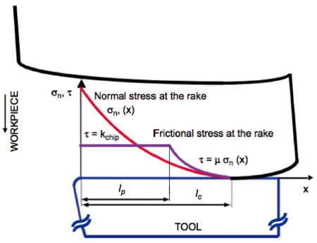
Fig. 3에는 공구와 칩 사이에 발생하는 마찰이 발생하는 영역의 응력 분포도에 대한 모델이 나타나있다. 수직 응력과 미끄럼 응력이 발생하는데, 고착 영역(
lp, Sticking Region)과 접촉 길이 영역(
lc, Chip-Tool Contact Length)에 따라 다르게 분포한다. 고착 영역에서는 수직 응력과 미끄럼 응력은 다음
식(7)을 따른다.
37
Fig. 3Normal and frictional stress distributions on the tool rake face10 (Adapted from Ref. 10 on the basis of open access)

2.4 마모 모델
공구 수명을 예측하기 위해 공구 마모 모델을 이용한다. 대표적인 공구 마모 모델로 Usui Wear Rate 모델이 있으며
식(8)과 같다. Usui
19 수식은 접착 마모(Adhesive Wear)에 대한 수식으로 구성되어 있다.
σn은 가공 중 공구에 가해지는 수직 응력을 의미하며, vs는 가공 속도를 뜻한다. A, B는 실험을 통해 계산된 계수이다. 따라서, 가공 조건에 따라 발생하는 온도(T)와 σn을 계산하고, 계수 A, B에 대한 실험적 관찰이 우선시 되어야 한다.
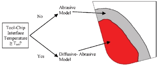
고속 가공이 가능해지면서 절삭 온도가 기존 가공보다 높게 발생한다. 높은 절삭 온도는 공구 재료의 확산 마모(Diffusive Wear)를 일으킨다. 접착 마모와 확산 마모를 같이 고려한 모델이 제안되었으며
식(9)와 같이 나타낸다.
D(
T)는 온도와 관련한 식으로 실험 관찰을 통해 결정되며,
Tact는
Fig. 4와 같이 확산 마모가 시작되는 온도를 의미한다. Uncoated Carbide Tool의 경우 약 700
oC에서 확산 마모가 시작되는 것으로 보고되었다.
38
Fig. 4Tool wear model selection as a function of the tool temperature19 (Adapted from Ref. 19 on the basis of open access)
3. FEM 모델 해석을 통한 결과
3.1 절삭력
기계 가공 중 발생하는 여러가지 결과들 중 절삭력은 가장 기초적으로 측정 및 관찰을 한다. 절삭력은 마모, 온도, 마찰, 재료 표면 등에 영향을 미치기 때문에 정확하게 예측하는 것이 필요하며, 정확도를 평가하기 위해 실험에서 측정한 결과와 비교하는 작업을 수행한다. 절삭력은 2장에서 설명한 물성 모델, 마찰, 마모에 의해 많은 영향을 받는 요인 중 하나이다.
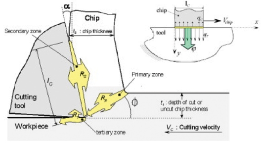
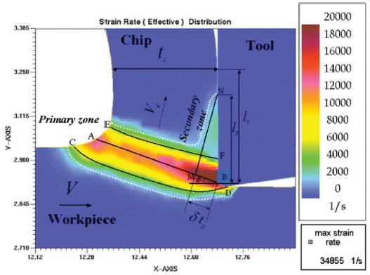
절삭력이 발생하는 주요 원인은 공구에 의해 칩이 생성되면서 변형 영역(Deformation Zones)에서 재료 소성으로 인해 발생한다.
39,40 Fig. 5에는 공구에 의해 생성되는 주 변형, 이차 변형, 삼차 변형 영역에 대해 나타나있다. 앞서 언급한 JC 모델과 같은 소성 변형 모델을 통해 주 변형과 이차 변형에서의 재료 변형, 변형 속도, 온도에 대해 예측 및 계산을 할 수 있다.
Fig. 5Deformation zones in the metal cutting process39 (Adapted from Ref. 39 on the basis of open access)
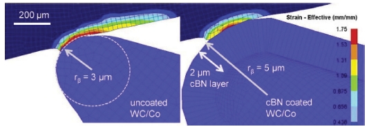
마이크로 가공 기술의 발달로 공구 끝단 형상에 따라 절삭력을 고려가 필요해졌다. 이에 따라 FEM 시뮬레이션에서 절삭력 예측을 위해 많은 연구가 되고 있다.
41-43 Fig. 6과 같이 마이크로 공구 끝 형상의 Round Edge 크기가 커질수록 절삭력이 커지는 것을 예측되었다. Round Edge 형상의 공구는접촉 및 Plunge Effect가 발생하여 절삭력이 발생한다. FEM 모델을 통해 공구 형상에 따라 절삭력 예측이 가능하다.
Fig. 6FE model for uncoated WC/Co and cBN coated micro-tools with their edge radii41 (Adapted from Ref. 41 on the basis of open access)

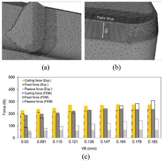
절삭력의 또다른 주요 원인 중 하나로 공구 마모가 있다. 공구마모는
Fig. 7(b)에 나타낸것과 같이 공구의 외부 형상을 변화시킨다. 변화된 공구형상은
Fig. 7(c)와 같이 Flank Wear Length가 증가 시 절삭력도 같이 증가한다. FEM 시뮬레이션을 통해서 실제와 동일하게 해석이 가능하다. 가공 조건 및 공구 마모 길이에 따라 측정한 절삭력과 다소 차이를 가지고 예측 된다. 가공 중 발생한 공구 마모의 길이가 고정된 가정에서 해석을 진행 했기 때문에 실제 절삭력과 오차율이 감소하였다.
Fig. 7(a) FE model indicating (a) the element size distribution in the workpiece on (b) the tool surface around the cutting edge (c) comparison between FE simulation results and cutting force measurements at different flank wear widths at cutting conditions L7. VB = re = 0.030 mm represents the sharp tool18 (Adapted from Ref. 18 on the basis of open access)

3.2 절삭 온도
절삭 온도는 가공 중 절삭력과 동시에 발생하는 중요한 분석결과 중 하나이다. 절삭 온도는 공구 수명과 절삭력, 표면상태 등 다양한 원인을 제공하기 때문에 분석이 반드시 필요하다. 절삭력과 마찬가지로 절삭 온도가
10,14,15,44-46 발생하는 부분과 동일하다. 발생한 절삭온도는
Fig. 8과 같이 각각 영역에서 공구, 칩, 재료로 열이 분산된다.
Fig. 8Chip formation with heat transfer during the orthogonal cutting process46 (Adapted from Ref. 46 on the basis of open access)

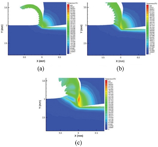
Fig. 9에는 최대 온도가 가공 조건에 따라 달라지는 해석 결과가 나타나있다.
47 절삭 온도는 공구, 재료, 칩으로 분산되며, 대부분의 온도가 공구 끝 부분에서 발생되고 집중 되는 것을 분석 할 수 있었다. Feed Rate이 증가 할수록 최대 절삭 온도 역시 같이 증가 하는 것을 확인할 수 있다.
Fig. 9Detailed comparison of maximum cutting temperature in the tool, workpiece and chip at the end of length of cut in the machining of the stainless steel with a cutting speed of 100 m/min and a depth of cut of 1 mm with a variable feed rate. (a) 0.05 mm/rev, (b) 0.1 mm/rev, and (c) 0.2 mm/rev 47 (Adapted from Ref. 47 on the basis of open access)

FEM 모델을 통해 절삭 온도가 발생하는 영역에서 공구, 칩, 재료로 분산되는 정도를 예측 할 수 있으며, 가공 조건 및 마모도에 따라 절삭 온도의 증가 정도를 예측 가능하다.
3.3 칩 생성(Chip Formation)
알루미늄 가공이나 일반강 재질 가공 시 대부분의 일반적인 가공에서는 연속칩(Continues Chip) (
Fig. 10(a))이
43,48 발생한다. 그러나, 티타늄, 인코넬, 고경도강 등 기존 재료와 다른 특성을 가진 재료의 경우 톱니형칩(Serrated Chip)이
27,33,49-51 발생한다. 연속칩은 전단띠(Shear Band)가 분리된 칩 속에 남아있지 않으며, 톱니형칩(
Fig. 10(b))의 경우 가공 후에도 칩 속에 전단띠가 지속적으로 남아 있게 되면서 형상이 변하게 된다 톱니형칩은 칩이 더 말리면서 절삭력이 다소 줄어든다.
27
Fig. 10(a) Continues chip formation,48 (b) Serrated chip formation52 (Adapted from Refs. 48 and 52 on the basis of open access)

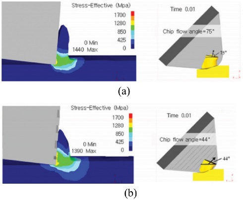
Kim et al.
13은 공구 표면 위에 패턴이 존재했을 시 Chip Flow Angle에 대한 해석을 진행했었다. 일반 공구의 경우 Chip Flow Angle이 약 75도 였으며 (
Fig. 11(a)), 패턴 공구는 Chip Flow Angle이 약 44도로 (
Fig. 11(b)), 패턴이 가진 방향으로 Chip이 회전하며, 패턴의 모양을 이용하여 칩 제어가 가능함을 FEM 모델을 통해 보였다.
Fig. 11Chip flow angle of (a) Non-patterned tool, (b) Perpendicular patterned tool13
Buchkremer et al.
53는 Chip Geometry에 대해서 파라메터를 결정하여 실험과 비교를 수행했다. 여러가지 가공 조건에 따라 Chip이 말리는 정도가 달라지면서 주기적인 Chip Breakage가 발생하는 것을 확인하였다. FEM 모델은 실제 실험에서 관찰된 Chip Geometry 이미지와 거의 유사하게 시뮬레이션이 가능하였다.
4. 최신 기계 공정에 대한 FEM 모델
4.1 극저온 가공 공정
극저온 가공 공정은 액체질소와 같이 극저온 상태의 액체를 절삭유 대신 가공 공정에 적용한 기술을 의미한다. FEM 모델과 관련한 연구가 그동안 매우 국소적으로 연구가 되어오고 있다. 본 장에서는 극저온 가공 공정과 관련한 FEM 모델링에 대해서 알아보았다.
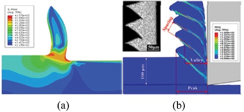
Davoudinejad et al.
54은 AdvantEdge를 이용하여 극저온 공정에 대해서 해석을 시도하였다. 극저온에 의한 Heat Transfer Coefficient의 범위는 46.7-5000 kW/m
2K에서 액체 질소의 Jet Radius를 1-3 mm 사이로 모델을 실시했다. 절삭력과 칩 생성에 대해서 해석을 실시했다.
Fig. 12와 같이 액체 질소로 인해 칩의 Peak-Peak 거리가 실제 실험과 유사하게 해석되는 것을 확인할 수 있었으며, 액체 질소는 절삭력과 마찰계수를 증가시키는 것으로 확인되었다.
Fig. 12Chip flow angle of (a) Non-patterned tool, (b) Perpendicular patterned tool54 (Adapted from Ref. 54 on the basis of open access)

Pusavec et al.
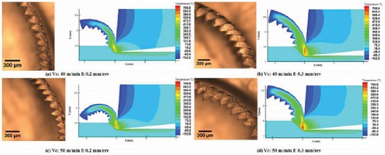
55은 극저온 액체와 기체 상태에 따라 절삭 온도가 감소 시키는 비율에 대해서 FEM 모델 해석을 실시하였다.
Fig. 13에 나타낸 극저온 FEM 해석 결과와 같이 액체상의 질소는 기체상에서보다 훨씬 많은 열을 감소시킬 수 있었다. 또한, 분사 방향에 따라서도 그 비율이 다른 것을 확인하였다. 가장 온도가 많이 발생하는 주변형 영역의 온도를 감소 시키기 위해서는 공구의 Rake 면과 Flank 면 두 곳에 동시에 분사 시킬 때 가장 많은 열을 감소 시키는 것으로 분석되었다.
Fig. 13Influence of cryogenic fluid on temperature distribution and material velocities in machining of Inconel 718 material, comparing different delivery locations and nitrogen phases55 (Adapted from Ref. 55 on the basis of open access)
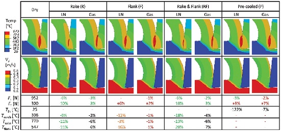
FEM 모델링 기법을 응용하여 극저온 공정을 위한 최적 액체질소 분사 방향과 온도 감소 비율, 극저온 공정이 칩 생성에 미치는 영향에 대해서 분석이 가능하였다.
4.2 CFRP 가공 공정
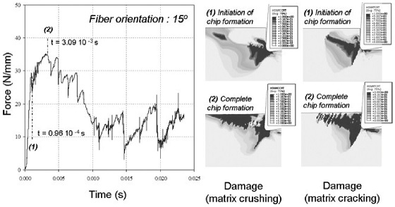
탄소 복합재(Carbon Fiber Reinforced Polymer, CFRP) 가공 공정은 금속 재료와 다른 가공 성질을 보이기 때문에, FEM 모델을 수립하는 연구가 지속적으로 진행 되고 있다. Santiuste et al.
56은 Fiber Orientation이 15°인 CFRP에 대한 절삭력과 FEM 모델 해석에 대해서 보고하였다.
Fig. 14에 나타낸 결과와 같이 공구가 CFRP에 진입한 초기 1 ms 시간동안에는 칩이 생성이 되었다. 그러나, 시간 증가에 따라 공구가 내부로 더 진입하게 되면서 CFRP가 파손이 되면서 일반적 칩 형태보다는crack에 의한 파손으로 절삭력이 낮아지는 것을 FEM 모델을 통해 분석하였다.
Fig. 14Modelling orthogonal cutting of GFRPs (fiber orientation 15°). Evolution of cutting force with cutting time (a) and matrix damage, crushing (b), and cracking (c), at chip initiation and complete chip formation56 (Adapted from Ref. 56 on the basis of open access)
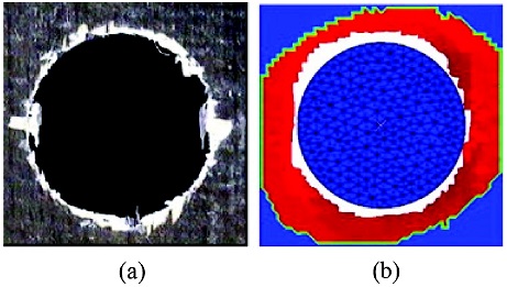
CFRP에 대한 드릴링 가공 공정이 주를 이루는데,
Fig. 15(a)와 같이 Delamination이 발생한다. 예측을 하기 위해 Ozden et al.
57은 CFRP 드릴링 공정 FEM 시뮬레이션 모델을 개발하였다. 3차원에 대한 드릴링 공정 모델을 개발하였으며, Hashin 이론을 이용하여 Delamination을 모사하였다.
Fig. 15(b)와 같이 드릴링 중 CFRP 내부에 발생하는 Delamination에 대해서 실험과 거의 유사하게 해석하였다. Step Drill의 Stage Ratio가 높을수록 절삭력과 Delamination이 감소 하는 것으로 예측하였다.
Fig. 15Entrance delamination (a) Experimental and (b) finite element57 (Adapted from Ref. 57 on the basis of open access)
5. 결론
가공 해석 FEM 모델을 수립하는 과정 중에서 실험을 통해 관찰된 칩 형상, 절삭력, 절삭온도등과 같이 해석이 요구되는 요인을 구분 하고 시간과 비용을 고려하여 해석 알고리즘을 정하는 것이 중요하다. 공구에 의해 재료에는 소성이 발생하게 되고 칩 생성이 된다. 이를 계산하기 위한 물성 모델은 다양하게 연구되고 있으며, 대표적으로는 JC 모델을 이용 한다. 시뮬레이션상에서 칩과 관련한 해석을 위해서는 Damage 또는 Flow-Softening을 고려한 모델이 추가가 되어야 한다. 가공 중 발생하는 마찰 모델은 고착 영역과 미끄럼 영역으로 구분되어 다르게 모델이 필요하나, 계산 시간에 대한 고려를 한다면 간단한 Coulomb 또는 Shear Friction 모델을 사용하길 권장한다. 공구 마모에 대한 FEM 예측 모델링을 구축하기 전에 실험 관찰을 통해 공구 마모 모델에 대한 계수를 사전에 작업이 요구된다. 정해진 계수를 통해 FEM 모델을 통해 실험 외 가공 조건에 대한 예측이 가능하다.
절삭력은 재료 소성 변형, 공구 형상, 공구 마모 등에 의해 영향을 받으며, FEM 모델을 이용하여 예측 및 분석이 가능하다. 모델은 여러가지 가정을 바탕으로 구성되기 때문에 실험치와 다소 상이하며, 이를 극복하기 위해 연구 진행이 필요하다. 절삭 온도는 절삭 공정에 큰 영향을 주는 요인으로 공구, 칩, 재료로 분산되는 온도에 대한 해석이 요구된다. FEM 모델을 통해 절삭 온도 해석이 시각적으로 해석이 가능하다. 일반적 가공 공정에서 관찰되는 연속칩에서 특수 합금 또는 고속 가공에서 불연속칩 또는 톱니형 칩이 관찰된다. 칩 형상 해석은 가공 메커니즘을 이해하기 위한 하나의 요인으로 FEM 모델을 통해 시각적 해석이 가능하다.
최신 기계 가공 중 극저온 가공 공정과 CFRP 가공 공정에 대한 FEM 모델 연구가 꾸준히 진행되고 있다. 극저온으로 인한 Heat Transfer Rate에 대한 정의가 요구되며 기체상태보다 액체상태, 분사 위치에 따라 절삭력, 칩 형상등에 영향을 미치는 것을 FEM 모델을 통해 해석이 가능하였다. CFRP는 일반적인 가공 재료와 특성이 다르기 때문에, FEM 모델을 통해 가공 메커니즘을 이해는 것이 필요하다. 가장 문제가 되는 Delamination에 대한 영향을 FEM 모델로 해석이 가능하며, 드릴의 형상에 따라 감소하는 결과를 예측가능하다.
CAE 기술 중 기계 가공 FEM 모델은 최신 기계 가공 공정 및 신소재가 개발될 때 가공 메커니즘을 이해하는데 아주 유용한 기술로써 앞으로 지속적인 연구가 필요한 분야이다.
ACKNOWLEDGMENTS
본 연구는 산업통산자원부의 미래산업선도기술개발[10053248, 과제명: 탄소섬유복합재(CFRP) 가공시스템 개발] 및 티타늄/CGI 가공을 위한 액체질소 적용 극저온 가공 공정 및 시스템개발연구(10048871)의 일환으로 수행되었음.
REFERENCES
- 1.
Oxley, P. L. B. and Young, H.-T., “The Mechanics of Machining: An Analytical Approach to Assessing Machinability,” Ellis Horwood Publisher, 1990.
10.1115/1.2888318
- 2.
Arrazola, P., Özel, T., Umbrello, D., Davies, M., and Jawahir, I., “Recent Advances in Modelling of Metal Machining Processes,” CIRP Annals, Vol. 62, No. 2, pp. 695-718, 2013.
10.1016/j.cirp.2013.05.006
- 3.
Markopoulos, A. P., “Cutting Mechanics and Analytical Modeling,” Finite Element Method in Machining Processes, pp. 11-27, 2013.
10.1007/978-1-4471-4330-7_2
- 4.
Wang, M., Gao, L., and Zheng, Y., “An Examination of the Fundamental Mechanics of Cutting Force Coefficients,” International Journal of Machine Tools and Manufacture, Vol. 78, pp. 1-7, 2014.
10.1016/j.ijmachtools.2013.10.008
- 5.
Kaymakci, M., Kilic, Z., and Altintas, Y., “Unified Cutting Force Model for Turning, Boring, Drilling and Milling Operations,” International Journal of Machine Tools and Manufacture, Vol. 54, pp. 34-45, 2012.
10.1016/j.ijmachtools.2011.12.008
- 6.
Ozturk, S. and Altan, E., “A Slip-Line Approach to the Machining with Rounded-Edge Tool,” International Journal of Advanced Manufacturing Technology, Vol. 63, Nos. 5-8, pp. 513-522, 2012.
10.1007/s00170-012-3941-6
- 7.
Ye, G., Xue, S., Tong, X., and Dai, L., “Slip-Line Field Modeling of Orthogonal Machining Pressure Sensitive Materials,” International Journal of Advanced Manufacturing Technology, Vol. 58, Nos. 9-12, pp. 907-914, 2012.
10.1007/s00170-011-3459-3
- 8.
Uysal, A. and Altan, E., “A New Slip-Line Field Modeling of Orthogonal Machining with a Rounded-Edge Worn Cutting Tool,” Machining Science and Technology, Vol. 18, No. 3, pp. 386-423, 2014.
10.1080/10910344.2014.925375
- 9.
Avevor, Y., Vincent, J., Faure, L., Moufki, A., and Philippon, S., “An Ale Approach for the Chip Formation Process in High Speed Machining with Transient Cutting Conditions: Modeling and Experimental Validation,” International Journal of Mechanical Sciences, Vol. 130, pp. 546-557, 2017.
10.1016/j.ijmecsci.2017.06.021
- 10.
Arrazola, P. J., “Investigations on the Effects of Friction Modeling in Finite Element Simulation of Machining,” International Journal of Mechanical Sciences, Vol. 52, No. 1, pp. 31-42, 2010.
10.1016/j.ijmecsci.2009.10.001
- 11.
Ducobu, F., Rivière-Lorphèvre, E., and Filippi, E., “Application of the Coupled Eulerian-Lagrangian (CEL) Method to the Modeling of Orthogonal Cutting,” European Journal of Mechanics-A/Solids, Vol. 59, pp. 58-66, 2016.
10.1016/j.euromechsol.2016.03.008
- 12.
Wu, H. and Zhang, S., “3D FEM Simulation of Milling Process for Titanium Alloy Ti6Al4V,” International Journal of Advanced Manufacturing Technology, Vol. 71, Nos. 5-8, pp. 1319-1326, 2014.
10.1007/s00170-013-5546-0
- 13.
Kim, D. M., Bajpai, V., Kim, B. H., and Park, H. W., “Finite Element Modeling of Hard Turning Process via a Micro-Textured Tool,” International Journal of Advanced Manufacturing Technology, Vol. 78, Nos. 9-12, pp. 1393-1405, 2015.
10.1007/s00170-014-6747-x
- 14.
Yang, Y. and Zhu, W., “Study on Cutting Temperature during Milling of Titanium Alloy Based on FEM and Experiment,” International Journal of Advanced Manufacturing Technology, Vol. 73, Nos. 9-12, pp. 1511-1521, 2014.
10.1007/s00170-014-5937-x
- 15.
Chen, L., Tai, B. L., Chaudhari, R. G., Song, X., and Shih, A. J., “Machined Surface Temperature in Hard Turning,” International Journal of Machine Tools and Manufacture, Vol. 121, pp. 10-21, 2017.
10.1016/j.ijmachtools.2017.03.003
- 16.
Arısoy, Y. M., Guo, C., Kaftanoğlu, B., and Özel, T., “Investigations on Microstructural Changes in Machining of Inconel 100 Alloy Using Face Turning Experiments and 3D Finite Element Simulations,” International Journal of Mechanical Sciences, Vol. 107, pp. 80-92, 2016.
10.1016/j.ijmecsci.2016.01.009
- 17.
Rotella, G. and Umbrello, D., “Finite Element Modeling of Microstructural Changes in Dry and Cryogenic Cutting of Ti6Al4V Alloy,” CIRP Annals-Manufacturing Technology, Vol. 63, No. 1, pp. 69-72, 2014.
10.1016/j.cirp.2014.03.074
- 18.
Malakizadi, A., Gruber, H., Sadik, I., and Nyborg, L., “An FEM-Based Approach for Tool Wear Estimation in Machining,” Wear, Vol. 368, pp. 10-24, 2016.
10.1016/j.wear.2016.08.007
- 19.
Attanasio, A., Ceretti, E., Fiorentino, A., Cappellini, C., and Giardini, C., “Investigation and FEM-Based Simulation of Tool Wear in Turning Operations with Uncoated Carbide Tools,” Wear, Vol. 269, Nos. 5-6, pp. 344-350, 2010.
10.1016/j.wear.2010.04.013
- 20.
Sadeghifar, M., Sedaghati, R., Jomaa, W., and Songmene, V., “Finite Element Analysis and Response Surface Method for Robust Multi-Performance Optimization of Radial Turning of Hard 300 m Steel,” International Journal of Advanced Manufacturing Technology, Vol. 94, Nos. 5-8, pp. 2457-2474, 2018.
10.1007/s00170-017-1032-4
- 21.
Mahnama, M. and Movahhedy, M., “Prediction of Machining Chatter Based on FEM Simulation of Chip Formation under Dynamic Conditions,” International Journal of Machine Tools and Manufacture, Vol. 50, No. 7, pp. 611-620, 2010.
10.1016/j.ijmachtools.2010.03.009
- 22.
Mohammadpour, M., Razfar, M., and Saffar, R. J., “Numerical Investigating the Effect of Machining Parameters on Residual Stresses in Orthogonal Cutting,” Simulation Modelling Practice and Theory, Vol. 18, No. 3, pp. 378-389, 2010.
10.1016/j.simpat.2009.12.004
- 23.
Adetoro, O. and Wen, P., “Prediction of Mechanistic Cutting Force Coefficients Using ALE Formulation,” International Journal of Advanced Manufacturing Technology, Vol. 46, Nos. 1-4, pp. 79-90, 2010.
10.1007/s00170-009-2079-7
- 24.
Vaziri, M., Salimi, M., and Mashayekhi, M., “A New Calibration Method for Ductile Fracture Models as Chip Separation Criteria in Machining,” Simulation Modelling Practice and Theory, Vol. 18, No. 9, pp. 1286-1296, 2010.
10.1016/j.simpat.2010.05.003
- 25.
Ozel, T., Llanos, I., Soriano, J., and Arrazola, P.-J., “3D Finite Element Modelling of Chip Formation Process for Machining Inconel 718: Comparison of FE Software Predictions,” Machining Science and Technology, Vol. 15, No. 1, pp. 21-46, 2011.
10.1080/10910344.2011.557950
- 26.
Ding, H., Shen, N., and Shin, Y. C., “Modeling of Grain Refinement in Aluminum and Copper Subjected to Cutting,” Computational Materials Science, Vol. 50, No. 10, pp. 3016-3025, 2011.
10.1016/j.commatsci.2011.05.020
- 27.
Karpat, Y., “Temperature Dependent Flow Softening of Titanium Alloy Ti6Al4V: An Investigation Using Finite Element Simulation of Machining,” Journal of Materials Processing Technology, Vol. 211, No. 4, pp. 737-749, 2011.
10.1016/j.jmatprotec.2010.12.008
- 28.
Johnson, G. R., “A Constitutive Model and Data for Metals Subjected to Large Strains, High Strain Rates and High Temperatures,” Proc. of the 7th International Symposium on Ballistics, 1983.
- 29.
Wang, B. and Liu, Z., “Shear Localization Sensitivity Analysis for Johnson–Cook Constitutive Parameters on Serrated Chips in High Speed Machining of Ti6Al4V,” Simulation Modelling Practice and Theory, Vol. 55, pp. 63-76, 2015.
10.1016/j.simpat.2015.03.011
- 30.
Denkena, B., Köhler, J., and Mengesha, M. S., “Influence of the Cutting Edge Rounding on the Chip Formation Process: Part 1. Investigation of Material Flow, Process Forces, and Cutting Temperature,” Production Engineering, Vol. 6, Nos. 4-5, pp. 329-338, 2012.
10.1007/s11740-012-0366-x
- 31.
Athavale, S. M. and Strenkowski, J. S., “Material Damage-Based Model for Predicting Chip-Breakability,” Journal of Manufacturing Science and Engineering, Vol. 119, No. 4B, pp. 675-680, 1997.
10.1115/1.2836808
- 32.
Yang, Y. and Li, J., “Study on Mechanism of Chip Formation during High-Speed Milling of Alloy Cast Iron,” International Journal of Advanced Manufacturing Technology, Vol. 46, Nos. 1-4, pp. 43-50, 2010.
10.1007/s00170-009-2064-1
- 33.
Sima, M. and Özel, T., “Modified Material Constitutive Models for Serrated Chip Formation Simulations and Experimental Validation in Machining of Titanium Alloy Ti-6Al-4V,” International Journal of Machine Tools and Manufacture, Vol. 50, No. 11, pp. 943-960, 2010.
10.1016/j.ijmachtools.2010.08.004
- 34.
Denguir, L., Outeiro, J., Fromentin, G., Vignal, V., and Besnard, R., “A Physical-Based Constitutive Model for Surface Integrity Prediction in Machining of OFHC Copper,” Journal of Materials Processing Technology, Vol. 248, pp. 143-160, 2017.
10.1016/j.jmatprotec.2017.05.009
- 35.
Özel, T. and Altan, T., “Determination of Workpiece Flow Stress and Friction at the Chip-Tool Contact for High-Speed Cutting,” International Journal of Machine Tools and Manufacture, Vol. 40, No. 1, pp. 133-152, 2000.
10.1016/S0890-6955(99)00051-6
- 36.
Childs, T., “Metal Machining: Theory and Applications,” Butterworth-Heinemann, 2000.
- 37.
Al-Zkeri, I. A., “Finite Element Modeling of Hard Turning,” Ohio State University, 2007.
- 38.
Yen, Y.-C., Söhner, J., Lilly, B., and Altan, T., “Estimation of Tool Wear in Orthogonal Cutting Using the Finite Element Analysis,” Journal of Materials Processing Technology, Vol. 146, No. 1, pp. 82-91, 2004.
10.1016/S0924-0136(03)00847-1
- 39.
Özel, T. and Zeren, E., “Determination of Work Material Flow Stress and Friction for FEA of Machining Using Orthogonal Cutting Tests,” Journal of Materials Processing Technology, Vol. 153, pp. 1019-1025, 2004.
10.1016/j.jmatprotec.2004.04.162
- 40.
Melkote, S. N., Grzesik, W., Outeiro, J., Rech, J., Schulze, V., et al., “Advances in Material and Friction Data for Modelling of Metal Machining,” CIRP Annals, Vol. 66, No. 2, pp. 731-754, 2017.
10.1016/j.cirp.2017.05.002
- 41.
Thepsonthi, T. and Özel, T., ”Experimental and Finite Element Simulation Based Investigations on Micro-Milling Ti-6Al-4V Titanium Alloy: Effects of CBN Coating on Tool Wear,” Journal of Materials Processing Technology, Vol. 213, No. 4, pp. 532-542, 2013.
10.1016/j.jmatprotec.2012.11.003
- 42.
Özel, T., Thepsonthi, T., Ulutan, D., and Kaftanoğlu, B., ”Experiments and Finite Element Simulations on Micro-Milling of Ti-6Al-4V Alloy with Uncoated and CBN Coated Micro-Tools,” CIRP Annals-Manufacturing Technology, Vol. 60, No. 1, pp. 85-88, 2011.
10.1016/j.cirp.2011.03.087
- 43.
Oliaei, S. N. B. and Karpat, Y., “Investigating the Influence of Friction Conditions on Finite Element Simulation of Microscale Machining with the Presence of Built-Up Edge,” International Journal of Advanced Manufacturing Technology, Vol. 90, Nos. 1-4, pp. 819-829, 2017.
10.1007/s00170-016-9456-9
- 44.
Rao, B., Dandekar, C. R., and Shin, Y. C., “An Experimental and Numerical Study on the Face Milling of Ti-6Al-4V Alloy: Tool Performance and Surface Integrity,” Journal of Materials Processing Technology, Vol. 211, No. 2, pp. 294-304, 2011.
10.1016/j.jmatprotec.2010.10.002
- 45.
Sui, S. and Feng, P., “The Influences of Tool Wear on Ti6Al4V Cutting Temperature and Burn Defect,” International Journal of Advanced Manufacturing Technology, Vol. 85, Nos. 9-12, pp. 2831-2838, 2016.
10.1007/s00170-015-8093-z
- 46.
List, G., Sutter, G., and Bouthiche, A., “Cutting Temperature Prediction in High Speed Machining by Numerical Modelling of Chip Formation and Its Dependence with Crater Wear,” International Journal of Machine Tools and Manufacture, Vol. 54, pp. 1-9, 2012.
10.1016/j.ijmachtools.2011.11.009
- 47.
Maranhão, C. and Davim, J. P., “Finite Element Modelling of Machining of AISI 316 Steel: Numerical Simulation and Experimental Validation,” Simulation Modelling Practice and Theory, Vol. 18, No. 2, pp. 139-156, 2010.
10.1016/j.simpat.2009.10.001
- 48.
Afazov, S., Ratchev, S., and Segal, J., “Modelling and Simulation of Micro-Milling Cutting Forces,” Journal of Materials Processing Technology, Vol. 210, No. 15, pp. 2154-2162, 2010.
10.1016/j.jmatprotec.2010.07.033
- 49.
Calamaz, M., Coupard, D., Nouari, M., and Girot, F., “Numerical Analysis of Chip Formation and Shear Localisation Processes in Machining the Ti-6Al-4V Titanium Alloy,” International Journal of Advanced Manufacturing Technology, Vol. 52, Nos. 9-12, pp. 887-895, 2011.
10.1007/s00170-010-2789-x
- 50.
Chen, G., Ren, C., Yang, X., Jin, X., and Guo, T., “Finite Element Simulation of High-Speed Machining of Titanium Alloy (Ti-6Al-4V) Based on Ductile Failure Model,” International Journal of Advanced Manufacturing Technology, Vol. 56, Nos. 9-12, pp. 1027-1038, 2011.
10.1007/s00170-011-3233-6
- 51.
Wu, H. and To, S., “Serrated Chip Formation and their Adiabatic Analysis by Using the Constitutive Model of Titanium Alloy in High Speed Cutting,” Journal of Alloys and Compounds, Vol. 629, pp. 368-373, 2015.
10.1016/j.jallcom.2014.12.230
- 52.
Ye, G., Xue, S., Jiang, M., Tong, X., and Dai, L., “Modeling Periodic Adiabatic Shear Band Evolution during High Speed Machining Ti-6Al-4V Alloy,” International Journal of Plasticity, Vol. 40, pp. 39-55, 2013.
10.1016/j.ijplas.2012.07.001
- 53.
Buchkremer, S., Wu, B., Lung, D., Münstermann, S., Klocke, F., et al., “Fe-Simulation of Machining Processes with a New Material Model,” Journal of Materials Processing Technology, Vol. 214, No. 3, pp. 599-611, 2014.
10.1016/j.jmatprotec.2013.10.014
- 54.
Davoudinejad, A., Chiappini, E., Tirelli, S., Annoni, M., and Strano, M., “Finite Element Simulation and Validation of Chip Formation and Cutting Forces in Dry and Cryogenic Cutting of Ti-6Al-4V,” Procedia Manufacturing, Vol. 1, pp. 728-739, 2015.
10.1016/j.promfg.2015.09.037
- 55.
Pusavec, F., Lu, T., Courbon, C., Rech, J., Aljancic, U., et al., “Analysis of the Influence of Nitrogen Phase and Surface Heat Transfer Coefficient on Cryogenic Machining Performance,” Journal of Materials Processing Technology, Vol. 233, pp. 19-28, 2016.
10.1016/j.jmatprotec.2016.02.003
- 56.
Santiuste, C., Soldani, X., and Miguélez, M. H., “Machining FEM Model of Long Fiber Composites for Aeronautical Components,” Composite Structures, Vol. 92, No. 3, pp. 691-698, 2010.
10.1016/j.compstruct.2009.09.021
- 57.
Isbilir, O. and Ghassemieh, E., “Numerical Investigation of the Effects of Drill Geometry on Drilling Induced Delamination of Carbon Fiber Reinforced Composites,” Composite Structures, Vol. 105, pp. 126-133, 2013.
10.1016/j.compstruct.2013.04.026