ABSTRACT
In order to help design engineers to adopt the Geometric Dimensioning & Tolerancing (GD&T), this paper develops a step-by-step method for tolerance design based on the function of the product and its parts. The procedure of this method consists of (1) analysis of functions using Key Characteristics (KC) and Datum Flow Chain (DFC), (2) selection of datum features, and (3) the selection of geometric tolerance types based on the functions. The rules and guidelines for the two latter steps are given and explained in detail, in order that the design engineer can understand the reasons for the rules and use them effectively. The method presented in this paper differs from other previous work, as it is based on the functions, whereas we note that previous work typically focuses on the automation of the tolerancing task without due consideration of functions. The paper also illustrates the developed method through two case studies: an axle-wheel assembly model and a simplified refrigerator model. This geometric tolerance design method is not complete yet in the coverage of various tolerances, e.g. size tolerances and profile, but may assist the beginning design engineer developing a mastery over GD&T.
-
KEYWORDS: Geometric tolerance, Tolerance design, Datum flow chain, GD&T, Automatic tolerancing
-
KEYWORDS: 기하 공차, 공차설계, 데이텀 흐름도, 기하공차 표준, 자동 공차설계
1. 서론
최근 제품의 품질에 대한 요구 수준이 높아짐에 따라, 공차 설계 및 관리에 대한 관심이 높아지고 있다. 그러나 오래 전에 기하공차(Geometric Tolerances)가 국제 표준으로 채택되었음에도 불구하고
1,2 많은 국내 기업들은 아직도 좌표공차 또는 플러스/마이너스(Plus-Minus) 공차를 사용하고 있다.
기업들이 기하공차를 쓰지 못하고 있는 가장 큰 이유는 그 개념을 이해하고 적용하는데 많은 노력이 필요하기 때문으로 보인다. 정도의 차이는 있으나 이 문제는 미국, 유럽 등에서도 현실적인 문제로 인식되어, 최근에는 설계자의 기하공차 설계를 돕기 위한 연구가 수행되고 있다. 대표적인 예로, CAD 모델만 입력해 주면 기하공차를 자동으로 부여하는 자동 공차설계 시스템을 위한 연구가 있다.
3-6 예를 들면, Hu & Xiong
3은 부품의 형체(Feature)를 점, 직선, 평면으로 나누고 형체에 따라 적용 가능한 기하공차를 제안하였다. Davidson 교수 그룹에서는 부품 형체의 크기 및 상관 관계로부터 적절한 데이텀과 기하공차를 유추하는 기법을 개발하는 등 공차설계의 자동화를 위해 연구하고 있다.
4,5 또, Anselmetti
6도 CAD 모델을 기반으로 기하공차 설계를 자동으로 수행하기 위한 소위 CLIC 시스템을 개발하였다.
그러나 이들 기존 연구들은 CAD 모델로부터 각 부품의 형체를 도출하고 부품 간의 연결 구조를 파악하여 이 정보만으로 공차설계를 수행하므로, 설계자가 의도한 기능을 자유롭게 반영하지 못한다는 한계가 있다. 이로 인해 적어도 두 가지 문제가 발생할 수 있다. 첫 번째로, 기능 관점에서 불필요한 공차가 지정되어 비용을 낭비할 수 있다. 예를 들면, 방향만 중요하고 위치는 중요하지 않은 형체에도 위치공차가 주어지고 그에 필요한 데이텀이 설정되어 검사 비용이 낭비될 수 있다. 두 번째로 기능과 무관한 데이텀 설정으로 인해 누적 공차가 발생할 수 있다. 즉, 형체의 크기와 기하학적 관계 만을 고려하여 데이텀을 설정하면 공차 체인(Chain)이 길어져 공차가 누적되고 이로 인해 품질 관리가 어려워진다.
일반적으로 기하공차 설계는 3단계로 나눌 수 있다. 첫 번째 단계는 데이텀을 설정하는 것이고, 두 번째는 공차의 종류를 결정하는 것이며, 세 번째는 공차 값을 부여하는 것이다. 세 번째 단계인 공차 값의 결정은 생산 비용을 고려하면서 상용 공차해석 프로그램을 사용하여 수행할 수 있으며, 최적화 알고리즘을 적용하면 최적의 공차 값을 찾을 수도 있다.
7-9
이 논문에서는 공차 설계의 첫 번째와 두 번째 단계, 즉 데이텀 및 기하공차의 선정을 돕는 룰(Rule)과 가이드라인(Guideline)을 개발하되, 기존 연구
3-6와 달리 제품과 부품의 기능에 필요한 최소한의 공차만 지정하도록 하여 경제성을 높이고자 한다. 즉, 기존 가이드라인을 따라 불필요한 기하공차가 부여되는 것을 방지하고 데이텀도 기능에 부합하게 설정함으로써 기능기반의 경제적 공차설계를 추구하는 것이다.
본 논문의 2장에서는 기능기반 고찰을 통해 데이텀과 기하공차의 종류를 설정하는 룰과 가이드라인을 개발하고 설명한다. 여기서 기능기반 고찰을 위해서는 부품들의 조립관계와 기능을 표현하는 DFC (Datum Flow Chain)를 활용한다. 3장에서는 2개의 사례를 통해 본 논문에서 개발된 룰과 가이드라인이 어떻게 적용되는지를 보인다.
2. 기능기반 기하공차 설계 기법
본 장에서는 기능기반 기하공차 설계를 위한 룰과 가이드라인을 도출한다. 각 절에서는 이를 위해 필요한 단계를 하나씩 설명한다.
2.1 중요 특징(KC)의 정의
제품의 기능 구현에 있어 중요하고 편차의 영향을 받는 제품의 치수 또는 기하학적 특징을 중요 특징(Key Characteristic) 또는 줄여서 KC라 한다.
10 KC는 기계적 기능뿐 아니라 심미성, 편리성, 감성 품질 등 광의의 기능을 실현함에 있어 중요한 특징들을 총망라한다.
KC의 의미는
Fig. 1의 예를 통해 쉽게 이해할 수 있다.
11 이 예는 차량의 차축(Axle)과 휠(Wheel)의 조립을 다루고 있는데, 차축은 동력원으로부터 전달되어 온 동력을 휠에 전달하는 기능을 한다.
Fig. 1에 보인 바와 같이 차축과 휠에는 여러 형체들이 있는데, 이 중 일부가 조립형체(Assembly Features), 즉 조립에 관여하는 형체이다. 예컨대, 차축의 Hub Face와 휠의 Wheel Plane이 조립되고 차축의 중앙에 있는 Rim이 휠의 Opening에 끼워지며 차축의 4개 Stud가 휠의 4개 Hole에 끼워져 조립되므로, 이들이 모두 조립형체이다.
Fig. 1Features of an axle and a wheel11
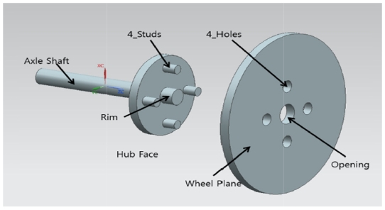
휠이 차축으로부터 동력을 전달받아 회전함으로써 차량을 추진하는 기능을 제대로 하려면, 최소한 두 개의 KC가 구현되어야 한다. 첫 번째 KC(KC_1)는 차축의 중심축과 휠의 중심축이 동축(Coaxial)이어야 한다는 것이다. 이 KC는 두 축의 상대적인 위치에 대한 것이며, 이 조건이 만족되지 않으면 차축이 회전할 때 휠이 편심된 채 회전하는 문제가 발생된다. 두 번째 KC(KC_2)는 차축의 중심축과 휠의 평면이 수직(Perpendicular)이어야 한다는 것이다. 이 KC는 두 형체의 상대적인 방향에 대한 것이며, 이것이 만족되지 않으면 차축이 회전할 때 휠이 하나의 평면 내에 머물지 않고 흔들리게(Wobble) 된다. 따라서 차축과 휠의 공차설계를 할 때는 이 두 KC가 반드시 구현되도록 해야 한다.
2.2 Datum Flow Chain (DFC)의 작성
DFC은 각 KC의 구현을 위해 필요한, 부품 사이 또는 형체 사이의 자유도 제약 관계를 표현하는 선도이다.
12 2.1절에서 고려한 차축-휠의 경우를 예로 들어 DFC에 대해 간략히 설명한다.
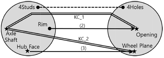
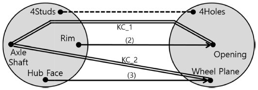
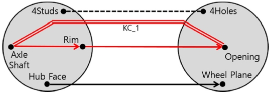
Fig. 2에 차축과 휠의 조립에 대한 DFC가 있는데, 좌측에는 차축과 그 형체들, 우측에는 휠과 그 형체들이 표시되어 있다. DFC에서 형체들은 점(Node, ●)으로 표시되는데,
Fig. 2에서 차축과 휠에 각각 4개와 3개의 형체가 있음을 알 수 있다. DFC에서 KC는 이를 결정하는 두 형체를 이중 실선으로 연결하여 표시한다.
Fig. 2에 2.1절에서 정의된 KC_1과 KC_2가 표시되어 있다.
Fig. 2DFC of the axle-wheel assembly11

DFC에서 서로 조립되는 형체들은 선으로 연결되는데 선에는 두 가지 종류, 즉 실선 화살표와 점선이 있고 이들은 서로 다른 의미를 가진다. 실선 화살표로 표시된 연결은 자유도 제약을 의미하는 Mate를 나타낸다. 구체적으로는 화살표가 시작되는 형체가 화살표가 가리키는 형체의 자유도를 괄호 안의 숫자만큼 제약한다. 점선은 자유도 제약과는 무관하고 단지 부품 간 체결을 보강하는 연결을 의미하며 Contact라 부른다. DFC를 작성하는 목적이 KC의 구현에 관여하는 형체들 사이의 자유도 제약을 분석하는데 있으므로 Mate만 중요하고, 따라서 Contact는 때로 무시되기도 한다.
Fig. 2에는 2개의 Mate가 있는데, 우선 차축의 Hub Face와 Wheel Plane 사이의 조립에 의해 휠의 3개 자유도가 제약된다. 두 번째 mate는 차축의 Rim과 휠의 Opening 사이 조립으로서 2개 자유도를 제약한다.
Fig. 2에서 나머지 하나 남은 자유도, 즉 차축의 축을 중심으로 회전하는 자유도는 여기서 고려하지 않는다. 그 이유는 KC_1, KC_2의 구현에 있어 이 자유도의 제약은 중요하지 않기 때문이다. 따라서 차축의 4개 Studs와 휠의 4개 Holes의 조립은 점선, 즉 Contact로 표시했다.
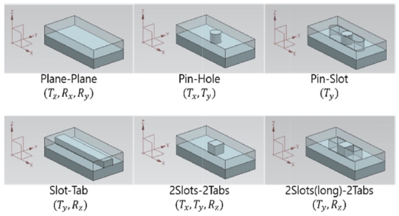
Fig. 2에 보인 바와 같이 자유도 제약에 사용되는 Mate에는 여러 종류가 있는데, Mate에 흔히 사용되는 조립형체 쌍을 정리하면
Fig. 3과 같다.
Fig. 3에는 각 Mate에 의해 제약되는 자유도를
Ti (
i축 방향의 병진 자유도)와
Ri (
i축 중심의 회전 자유도)로 표시하였다.
Fig. 3에 보인 핀과 구멍은 모두 길이가 짧아 2개의 회전 자유도(
Rx,
Ry)를 제약하지 못하는 것으로 간주하였다.
Fig. 3Mating feature pairs with constrained dof4
2.3 데이텀(Datum)의 설정
이제 KC를 구현하는 공차설계의 첫 단계인 데이텀 설정에 대해 살펴본다.
2.3.1 데이텀의 조건
데이텀(Datum)은 부품의 가공 및 검사에 있어 기준이 되는 면 또는 직선이고, 이를 정의하는 형체를 데이텀 형체라 한다. 일반적으로 데이텀이 갖추어야 하는 조건 또는 역할은 세 가지가 있는데 (1) 접근 용이성, (2) 측정의 재현성 보장, (3) 기능의 구현 보장이 있다. 즉, 데이텀은 사용하기 쉽도록 접근이 용이해야 하고, 여러 번 측정해도 동일한 결과를 얻을 수 있도록 안정적이어야 하며, 조립과 기능이 잘 구현될 수 있도록 설정해야 한다.
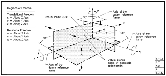
데이텀이 적절하게 설정되면
Fig. 4와 같이 데이텀 좌표계가 정의되고, 부품이 데이텀 좌표계에 놓이면 부품은 그 위치와 자세가 결정되며(즉, 자유도가 제약되며) 그 상태에서 측정된다. 따라서 측정의 재현성이 보장되려면, 부품의 자유도 제약이 항상 동일하게 이루어지도록 안정적인 데이텀을 선정해야 한다.
Fig. 4

보통 조립품을 구성하는 부품 중에는 조립 공정의 시작이 되는 부품이 하나 있다. 즉, 이 부품에 다른 부품이 조립됨으로써 조립 공정이 시작된다. 이를 베이스 부품(Base Part)이라 부르기로 한다.
베이스 부품이 아닌 부품을 검사 또는 측정할 때에는, 이들이 이전의 서브어셈블리에 조립될 때 갖게 될 상대적인 자세 및 위치를 재현하는 것이 중요하다. 그 이유는 이 위치와 자세가 그 부품의 완성품에서의 상태이고, 부품의 공차는 최종 완성품에서의 기능을 만족하도록 관리되어야 하기 때문이다. 따라서 베이스 부품이 아닌 부품의 데이텀 형체는 조립형체 중에서 선정해야 한다. 이를 통해 데이텀이 갖추어야 하는 요건 중 세 번째, 즉 기능의 구현이 보장될 수 있다. 한편, 베이스 부품의 경우에는 물론 모든 형체가 데이텀 형체가 될 수 있다.
2.3.2 데이텀 선정 룰(Rules)
부품이 3차원 공간에서 가질 수 있는 자유도는 6개이므로 6개 자유도를 제약하는 데이텀 조합을 사용하는 것이 보통이다. 그러나, 검사하고자 하는 기하공차가 6개 자유도 모두의 제약을 필요로 하지 않는 경우, 또는 부품 자체의 형상이 갖는 대칭성(예: 축대칭)으로 인해 6개의 자유도를 정의할 수 없는 경우에는 6개 미만의 자유도 제약이 되도록 데이텀을 선정하면 된다.
데이텀들의 다양한 조합은 여러 기존 연구
3-6에서 각자의 방법으로 표현하고 있으나 대부분 수학적 엄밀성을 추구하여 이해하기 어렵다. 본 논문에서는 이들을 종합하고 개편하여 실용성이 높은 데이텀 조합만을
Table 1에 정리하였다. 자유도 제약을 표현함에 있어
Ri는 회전 자유도,
Ti는 병진 자유도를 의미하고, 데이텀 평면(PL)과 데이텀 축(A)의 방향은 괄호 안에 ⊥(수직) 또는 ∥(평행)를 사용하여 표시했다.
Table 1Common datum feature sets and corresponding degrees of freedom constrained by them
Table 1
|
No. |
Datum features*1
|
CDOF*2
|
|
Primary |
Secondary |
Tertiary |
|
DS#1 |
PL(⊥z) |
|
|
Rx, Ry, Tz
|
|
DS#2 |
A(∥z) |
|
|
Tx, Ty, |
|
DS#3 |
PL(⊥z) |
A(∥z) |
|
Rx, Ry, Tx, Ty, Tz
|
|
DS#4 |
PL(⊥z) |
PL(⊥y) |
|
Rx, Ry, Rz, Ty, Tz
|
|
DS#5 |
A(∥z) |
A(∥y) |
|
Rx, Ry, Rz, Tx, Ty, Tz
|
|
DS#6 |
PL(⊥z) |
A(∥z) |
point(∉z)*3
|
Rx, Ry, Rz, Tx, Ty, Tz
|
|
DS#7 |
A(∥z) |
PL(∥z) or
point(∈z) |
point(∉z)*3
|
Rx, Ry, Rz, Tx, Ty, Tz
|
|
DS#8 |
PL(⊥z) |
PL(⊥y) |
PL(⊥x) |
Rx, Ry, Rz, Tx, Ty, Tz
|
Table 1의 데이텀 조합들 중 대부분은 1, 2, 3차 데이텀의 순서를 바꾸어도 동일한 자유도를 제약한다. 따라서 어느 형체를 선행 데이텀으로 선정할 지를 결정해야 하는데, 데이텀의 재현성이 보장될 수 있도록 주어진 부품에서 가장 안정적인 형체를 1차 데이텀으로 선택하는 것이 좋다. 이 기준을 포함하고, Haghighi 등
5이 제안한 룰 중에서 실용성 위주로 발췌한 기준들을 합하여 데이텀 형체 선정의 가이드라인들을 정리하면
Table 2와 같다.
Table 2Guidelines for datum feature selection
Table 2
|
No. |
Guideline |
|
DG#1 |
Datum features of a non-base part should be selected among its assembly features. |
|
DG#2 |
The largest eligible feature is selected for the primary datum unless otherwise required for the functions of the part. |
|
DG#3 |
The form of the primary datum feature should be controlled to ensure repeatable inspections. |
|
DG#4 |
The orientation of the secondary and tertiary datum features should be controlled with respect to the primary datum. |
Table 2에서 DG#1은, 2.4.1절에서 설명한 바와 같이 베이스 부품이 아닌 경우 조립형체 중에서 데이텀 형체를 선정하여야 함을 의미한다. DG#2는 후보 형체 중에서 가장 큰 형체를 1차 데이텀으로 사용함으로써 측정의 재현성을 확보하기 위한 것이다. 여기서 형체들의 크기란 축의 경우 그 길이를 의미하고 평면의 경우 가장 긴 변의 길이를 의미한다. DG#3과 DG#4도 데이텀 좌표계(Datum Reference Frame, DRF) 정립의 명확성과 재현성을 위한 것이다. 즉, 1차 데이텀 형체는 형상이 관리되어야 하고, 하위 데이텀 형체들은 1차 데이텀을 기준으로 방향(많은 경우 수직)이 관리되어야 한다는 것이다.
2.4 기하공차 종류의 후보 선정
각 부품에서 데이텀이 결정되었으면, 공차설계의 다음 단계는 형체 각각에 필요한 기하공차를 선정하는 것이다. 대상 형체와 데이텀 형체, 그리고 이들의 기하학적 관계에 따라 어떤 기하공차가 적용될 수 있는 지는 기하공차 표준
1,2을 따라 정할 수 있다. Hu & Xiong
3을 참고하여 흔히 사용되는 대상 및 데이텀 형체 조합에 대한 기하공차 후보를 나열하면
Table 3과 같다.
Table 3에서 1번 및 8번 룰(T1, T8)은 형상 공차를 의미하며, 형체의 기능에 따라 복수 후보 중 가장 적절한 것을 선택하면 된다. 데이텀이 복수인 경우에는, 각 데이텀에 대한 기하공차 후보들을 모두 고려한다. 기하공차 후보가 복수인 경우, 2.2절에서 설명한 DFC를 활용하여 기능기반으로 선정한다. 다음 절에서 그 방법을 설명한다.
2.5 KC 구현 경로와 기하공차 종류 선정
2.1절에서 설명한 KC가 구현되려면, DFC상에서 KC를 결정하는 두 개의 형체가 Mate만으로 이루어진 실선 경로(Path)로 연결되어야 한다. 왜냐하면, 경로 상의 모든 형체들이 실선으로 연결되어야만 그들 사이에 자유도 제약 관계가 성립되어 결국 KC가 요구하는 기하학적 관계가 만족될 수 있기 때문이다.
예를 들어
Fig. 2의 KC_1이 구현되려면, KC_1을 결정하는 Axle Shaft와 Opening이 실선 경로로 연결되어야 한다. 이를 위해서는 차축의 Axle Shaft와 Rim만 Mate(즉, 자유도 제약 관계)로 연결되면 되므로
Fig. 5와 같이 된다. Axle Shaft와 Rim은 하나의 부품 내에 있으므로 이들 사이의 자유도 제약 관계가 기하공차로 명시되어야 한다. 어떤 기하공차를 사용해야 할지는, KC 경로 상 형체들의 관계와 KC_1을 고려하여
Table 3의 후보 기하공차 중에서 결정한다. 그 결과는 3.1.3절에서 보인다.
Fig. 5Mate path through features for KC_1 delivery

요약하면, 일반적으로 KC의 구현 경로를 완성하기 위해 적절한 기하공차를 선정함으로써 기능기반의 공차설계가 이루어질 수 있다. 여기서 KC의 구현 경로는 가급적 적은 개수의 형체를 거치도록 하는 것이 좋은데, 그 이유는 형체를 적게 거칠수록 공차 누적이 적어지기 때문이다.
3. 적용 예
이 장에서는 앞 장에서 설명한 기능기반 기하공차 설계법을 2개의 예제에 적용하여 그 효용성을 보인다. 이 2개의 예제는 앞서 개발된 룰과 가이드라인을 폭 넓게 고찰할 수 있도록 선정되었다. 특히, 첫 번째 예제는, 본 논문의 룰과 가이드라인을 적용한 결과를 참고문헌의
11 결과와 비교하여 검증한다는 의미를 가지고 있다.
차축과 휠의 조립 문제에 대해서는 이미 2장에서 KC와 DFC 작성까지 설명하였으므로 바로 데이텀 설정과 기하공차의 종류 선정을 설명한다.
3.1.1 Datum의 설정
차축과 휠의 두 부품 중에서 차축을 베이스 부품으로 간주하여 휠이 차축에 조립되는 것으로 본다. 차축은 베이스 부품이므로 모든 형체가 데이텀이 될 수 있고,
Table 2의 가이드라인에 따라 이를 결정한다. 먼저 DG#2에 따라 Axle Shaft가 1차 데이텀 형체로 선정되고, Hub Face가 2차 데이텀 형체로 선정된다. 이 두 개의 데이텀 형체는
Table 1의 DS#3에서 1, 2차 데이텀의 순서만 바뀐 것이므로 5개의 자유도를 제약하며 이것으로 충분하다(2.2절 참조).
다음으로 휠은 베이스 부품이 아니므로,
Table 2의 DG#1에 따라 조립형체인 Opening과 Wheel Plane이 데이텀 형체 후보가 된다. DG#2에 따라 Wheel Plane이 1차 데이텀 형체, Opening이 2차 데이텀 형체로 선정된다. 이 두 데이텀 형체 조합은
Table 1의 DS#3에 해당되어 역시 5개의 자유도만 제약됨을 의미한다.
Fig. 6의 DFC에서는 이렇게 선정된 데이텀 형체들을 별표(★)로 표시하였다.
Fig. 6DFC of the axle-wheel assembly with datum features(★) selected
3.1.2 기하공차의 종류 선정
이제 앞 절에서 선정한 데이텀을 사용하여 각 형체에 필요한 기하공차를 선정해야 한다. 우선 차축부터 살펴보면(
Table 4 참조), 1차 데이텀 형체인 Axle Shaft는
Table 3의 T8에 의해 진원도(○), 원통도(⌭), 또는 진직도(─)의 형상공차를 가질 수 있다. 이는 DG#3과 부합한다. 2차 데이텀 형체인 Hub Face는 평면 형체이고 참조 데이텀이 축이므로 T4에 따라 위치도(⌖) 또는 직각도(⊥)를 가질 수 있으나, (
Table 3의 주석에 따라) FOS가 아니므로 직각도(⊥)를 선택한다. 이 선택은 DG#4와 부합한다. Rim은 원통 형상이고, 데이텀이 핀 형체와 평면 형체이기 때문에 T9, T15에 해당되어, 각각 동심도(◎), 런아웃(

), 전체런아웃(

) 및 위치도(⌖), 직각도(⊥)가 후보가 된다. 마지막으로 4개의 Stud는 핀 형체이고 데이텀이 핀 형체 및 평면 형체이기 때문에 T10, T15에 해당된다. 따라서 위치도(⌖), 평행도(

) 및 위치도(⌖), 직각도(⊥)가 후보가 된다.
휠의 형체들에 대해서도
Table 4와 같이 유사하게 기하공차 후보들을 선정할 수 있다. Wheel Plane은 참조할 데이텀이 없으므로 T1에 의해 평면도(

) 또는 진직도(─)가 후보가 되지만, FOS가 아니므로 평면도(
)로 확정한다. 휠의 Opening 에서는, T15에 따라 위치도(⌖)와 직각도(⊥)가 후보가 되는데 DG#4에 따라 직각도(⊥)를 선정한다. 4개의 Hole은 차축의 4개 Stud와 마찬가지로 T15 및 T10에 따라 각각 위치도(⌖), 평행도(
) 및 위치도(⌖), 직각도(⊥)가 후보가 된다.
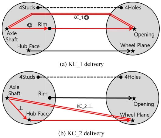
3.1.3 KC 구현 경로와 기하공차 종류 선정
Table 4에서 복수의 기하공차 후보가 존재하는 경우, 기능을 기반으로 하여 적절한 것을 선정해야 한다. 우선 Axle Shaft는 회전체이므로 질량 불균형으로 인한 진동을 방지하기 위해 그 형상을 원통도(⌭)로 제어하기로 한다.
Rim의 기하공차는 2.5절에서 설명한 KC 구현 경로를 이용해 결정할 수 있다. 즉,
Fig. 5에서 Axle Shaft와 Opening 사이의 동축성을 의미하는 KC_1이 구현되려면, KC 구현 경로 상에서 Axle Shaft와 Rim 사이에도 동심도(◎)가 필요함을 알 수 있다. 이 결과를
Fig. 7(a)에 표현하였다. 여기서 중요한 것은 Hub Face를 데이텀으로 하는 Rim의 위치도(⌖)나 직각도(⊥)는 KC_1의 구현에 있어 중요하지 않다는 것이며, 따라서
Table 4에서 이들 후보는 채택되지 않는다.
Fig. 7Determination of geometric tolerances using KC delivery paths for the axle-wheel assembly

KC_2의 구현 경로 구성과 이로 인한 기하공차의 부여도 동일한 방법으로 할 수 있으며, 그 결과가
Fig. 7(b)에 나타나 있다. 즉, Axle Shaft와 Wheel Plane 사이의 직각을 의미하는 KC_2를 구현하기 위해서는, Hub Face가 Axle Shaft를 데이텀으로 하는 직각도(⊥)를 가져야 하는데, 이는 이미
Table 4에서 선정된 바와 같다.
Fig. 7의 기하공차들은
Fig. 7(a)의 동심도가 참고문헌
11에는 위치도로 되어 있는 점을 제외하고는 참고문헌의 결과와 거의 동일하다. 기하공차 이론에서 위치도는 동심도를 대체하는 기하공차로 흔히 사용되므로,
Fig. 7의 결과는 참고문헌
11의 결과와 일치한다고 볼 수 있다. 이로써, 참고문헌
11에는 체계적으로 설명되어 있지 않은 기하공차 선정이 본 논문에서 개발한 기법에 의해 체계적으로 이루어질 수 있음을 확인하였다.
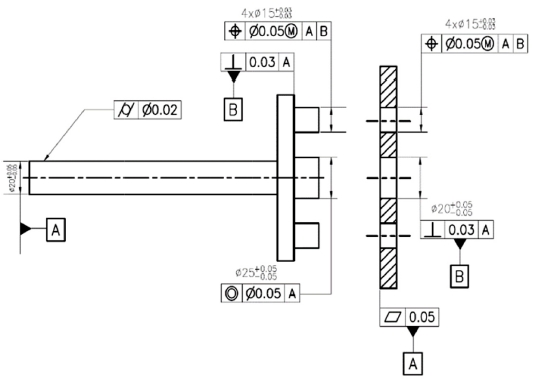
Table 4에서 차축과 휠의 Stud 및 Hole에 주어질 기하공차는 KC_1, KC_2로는 확정되지 않지만 임의로 위치도를 선정하고, 지금까지 선정된 데이텀과 기하공차를 모두 반영하여 차축과 휠의 도면 예를 보이면
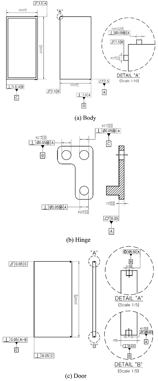
Fig. 8과 같다.
Fig. 8의 공차 값들을 제대로 결정하려면 공차설계의 3단계인 공차 값 결정 과정을 거쳐야 하는데, 이는 본 논문의 영역이 아니므로 임의의 값을 입력하였다.
Fig. 8Example drawings for the axle and the wheel

3.2 냉장고 모델
두 번 째 사례로 간단한 냉장고 모델을 고려한다.
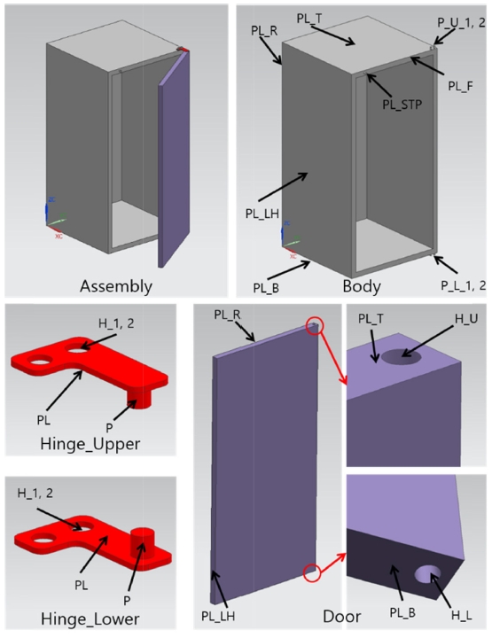
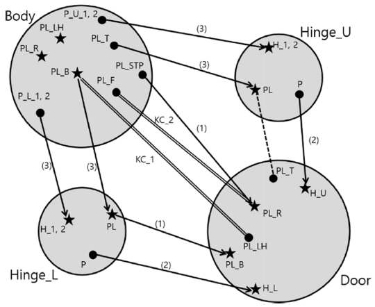
Fig. 9에 냉장고를 구성하는 부품들과 그 형체들이 표시되어 있다. Body가 베이스 부품이고, Body의 위 아래에 2개 Hinge가 조립된 후 Hinge의 2개 핀에 Door의 위 아래 구멍이 조립되어 회전하는 구조이다.
Fig. 9Features of the refrigerator model
3.2.1 KC의 정의 및 DFC의 작성
냉장고 모델에서도 두 가지 KC를 고려하기로 한다. 첫 번째 KC (KC_1)는 Body의 밑면(PL_B)과 Door의 좌측면(PL_LH)이 조립 후 직각을 이뤄야 한다는 것이고, 두 번째 KC (KC_2)는 Door의 뒷면(PL_R)과 Body의 앞면(PL_F) 사이 간격(Gap)이 일정하도록 서로 평행해야 한다는 것이다.
각 부품의 조립형체와 자유도 제약을 고려하여 DFC를 그리면
Fig. 10과 같다.
13 2개의 힌지(Hinge_U, Hinge_L)는 그 평면들(PL)이 Body의 위, 아래면(PL_T, PL_B)과 각각 Mate되어 3개 자유도가 제약되고, 그 구멍들(H_1,2)이 Body의 핀들(P_U_1,2, P_L_1,2)과 Mate되면서 나머지 3개 자유도가 제약된다. Door는 위, 아래 두 개의 구멍들(H_U, H_L)이 두 힌지의 핀들(P)과 Mate되어 4개 자유도가 제약되면서 회전축이 결정되고, 아래면(PL_B)이 Hinge_L의 평면(PL)과 Mate되면서 회전축 방향의 병진운동 자유도가 제약된다. 나머지 1개 자유도, 즉 Door가 열고 닫히는 회전 자유도는 Door의 뒷면(PL_R)이 Body의 스토퍼 평면(PL_STP)과 Mate되면서 제약된다. 이와 같이, 회전축을 기반으로 하는 조립을 축중심 조립(Axial Assembly)이라 한다.
Fig. 10DFC of the refrigerator model with datum features selected
3.2.2 Datum의 설정
Body는 베이스 부품이고 직육면체 형태이므로 윤곽면들을 이용하여 데이텀 조합(DS#8)을 설정하는 것이 적절하다. DG#2를 따라 윤곽면의 크기에 따라 우선 순위를 정하면 PL_R, PL_LH, PL_B순이 되지만, KC_1의 측정 관점에서 보면 냉장고가 수직으로 서도록 PL_B, PL_R, PL_LH 순으로 1, 2, 3차 데이텀 형체를 설정하는 것이 바람직하다.
Hinge와 Door는 베이스 부품이 아니므로 조립 형체 중에서 데이텀 형체를 선정한다. Hinge의 조립형체에는 PL, H_1, H_2가 있는데, DG#2에 따라 PL을 1차 데이텀, H_1을 2차 데이텀, H_2를 3차 데이텀으로 설정한다(DS#6). Door는 축중심 조립되어 자유도 제약이 이루어 지므로, H_U와 H_L을 연합한 회전축을 1차 데이텀으로 설정하고, PL_B를 2차 데이텀, PL_R을 3차 데이텀으로 설정한다(DS#7).
Fig. 10의 DFC에 선정된 데이텀 형체들을 별표로 표시하였다.
3.2.3 기하공차의 종류 선정
Body의 1차 데이텀인 PL_B의 기하공차로는
Table 3의 T1과 DG#3에 따라 평면도(
)를 선정한다. 2차 데이텀인 PL_R의 기하공차로는 T7과 DG#4에 따라 PL_B를 데이텀으로 하는 직각도(⊥)를 선정한다. 마찬가지로 3차 데이텀인 PL_LH에는 1차 데이텀 및 2차 데이텀과의 직각도(⊥)를 부여한다.
Body의 PL_T, PL_F, PL_STP는 모두 3개의 평면 데이텀 중 2개와는 수직이고 1개와는 평행이므로, T7과 T5에 의해 직각도(⊥), 평행도(
)가 후보가 된다. 일반적으로 평면의 방향은 하나의 평면을 데이텀으로 하는 평행도로 규정하거나 두 평면을 데이텀으로 하는 직각도로 규정할 수 있으나, 전자가 간단하므로 평행도를 선택한다. Body의 4개 핀들(P_U_1, 2 및 P_L_1, 2)은 3개의 평면 데이텀과 수직 또는 평행이므로, T13과 T15에 따라 각각 위치도(⌖), 직각도(⊥) 및 위치도(⌖), 평행도(
)가 후보가 된다.
Hinge의 1차 데이텀인 PL은 T1과 DG#3에 의해 평면도(
)를 가져야 하고, 2차 및 3차 데이텀인 H_1,2는 T15에 의해 위치도(⌖) 또는 직각도(⊥)가 후보이지만 DG#4에 따라 직각도를 선택한다. 핀(P)은 T15, T10에 의해 PL을 데이텀으로 위치도(⌖), 직각도(⊥), H_1,2를 데이텀으로 위치도(⌖), 평행도(
)를 기하공차 후보로 갖는다.
Door의 H_L은 T8과 DG#3에 따라 진원도(○), 원통도(⌭), 진직도(─)를 후보로 갖는다. H_L과 연합하여 1차 데이텀을 형성하는 H_U는 H_L과 동축이어야 하므로, H_L을 데이텀으로 하는 기하공차 후보, 즉 동심도(◎), 원형런아웃(
), 전체런아웃(
) 중에서 동심도를 선정한다. 2차 데이텀인 PL_B는 T4에 의해 직각도(⊥)를 가지며, 3차 데이텀인 PL_R은 T2, T9에 의해 H_UL을 데이텀으로 평행도(
), PL_B를 데이텀으로 직각도(⊥)를 기하공차 후보로 가진다. PL_LH의 경우, T2, T7에 따라 H_U,L을 데이텀으로 평행도(
), PL_R과 PL_B를 데이텀으로 직각도(⊥)를 후보로 가진다.
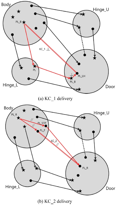
3.2.4 KC 구현 경로와 기하공차 종류 선정
우선 Door의 1차 데이텀인 H_L의 기능을 고려하면, DG#3에 의해 형상이 중요하므로 원통도를 선정한다.
이제
Table 5에 열거된 후보 기하공차 중에서 KC 구현을 위해 필요한 것을 선정하기 위해 2.5절의 방법을
Fig. 10의 DFC에 적용한다. 즉,
Fig. 11과 같이 KC_1과 KC_2의 구현 경로를 그려, KC가 구현되기 위해 요구되는 형체간의 기하공차를 결정하는 것이다. KC_1은
Fig. 11(a)에 보인 바와 같이 Door의 PL_LH가 PL_B에 대해 수직일 것을 요구하므로
Table 5의 15번 항목에서 PL_B에 대한 직각도를 선정한다. KC_2는
Fig. 11(b)와 같이 Body의 PL_F와 PL_STP가 PL_R 데이텀과 평행하면 구현되는데, 이미
Table 5의 5, 6번 항목에서 평행도가 선정되었으므로 만족된다.
Fig. 11Determination of geometric tolerance using KC delivery paths for the refrigerator model

Fig. 11에서 KC 구현 경로를 작성함에 있어 가급적 최단 경로를 선정하였으며 이는 앞에서 설명한 바와 같이 공차의 누적을 최소화하기 위한 것이다.
Table 5에서 아직 정해지지 않은 기하공차들은 KC_1, KC_2로는 정해지지 않는 것이며, 다른 KC에 의해 정해질 수 있을 것이다. 예를 들어, Door와 Body 사이의 측면 갭 크기를 KC로 삼았다면, 다수의 위치도, 윤곽도, 치수공차 등이 필요할 것이다.
Table 5에서 정해지지 않은 기하공차는 임의로 선정하여, 냉장고 부품의 완성된 도면 작성 예를 보이면
Fig. 12와 같다.
Fig. 12Example drawings for the refrigerator parts
4. 결론
본 논문에서는 기하공차에 익숙하지 않은 설계자들이 공차설계를 쉽게 할 수 있도록 돕기 위해 기하공차 설계 방법론을 개발하였다. 이 분야의 기존 연구들은 대체로 CAD 모델로부터 자동으로 기하공차를 유추하는 방식을 택하고 있으나 이는 설계자의 의도를 충분히 반영하지 못하는 한계점을 가지고 있다. 본 연구에서는 KC와 DFC를 통해 제품의 기능에 관한 설계자의 의도가 충분히 반영될 수 있는 방법론을 개발하였고, 이해하기 쉬운 용어를 사용하여 실질적인 도움이 되고자 하였다.
개발된 기능기반 기하공차 설계 방법론에서는 우선 KC를 정의하고, KC의 구현을 위해 부품의 형체들 사이에 어떤 자유도 제약이 이루어져야 하는 지를 설계하여 DFC를 작성한다. 그 다음으로 개발된 룰과 가이드라인에 따라 데이텀을 설정하고 형체별로 기하공차 종류의 후보를 도출한다. 마지막으로 앞서 설계하고 작성한 DFC를 활용하여 KC 즉 기능이 구현되기 위해 적절한 기하공차가 무엇인지를 선정한다.
본 논문에서 개발된 기하공차 설계법은 아직 모든 경우에 적용되기에는 한계를 가지고 있다. 예를 들면 크기 공차, 윤곽도, 대칭도 등과 재료조건이 아직 포함되어 있지 않다. 그러나 기하공차에 대해 완벽하게 이해하지 못하는 초보 설계자에게는 좋은 길잡이가 될 정도의 완성도는 가지고 있으므로, 이를 활용하면 초보적인 수준의 기능기반 기하공차 설계를 할 수 있을 것이다.
향후 더 많은 사례 연구를 통해 완성도와 범용성이 높은 방법론을 개발할 계획이며, 이를 통해 모든 기계 설계 문제에서 저비용으로 기능을 구현할 수 있는 양질의 기하공차 설계가 가능해질 것으로 기대한다.
ACKNOWLEDGMENTS
본 연구는 2014 홍익대학교 학술연구진흥비의 지원으로 수행되었으며, 이에 감사합니다.
REFERENCES
- 1.
- 2.
- 3.
Hu, J. and Xiong, G., “Dimensional and Geometric Tolerance Deign Based on Constraints,” The International Journal of Advanced Manufacturing Technology, Vol. 26, Nos. 9-10, pp. 1099-1108, 2005.
10.1007/s00170-004-2086-7
- 4.
Mohan, P., Haghighi, P., Vemulapalli, P., Kalish, N., Shah, J. J, et al., “Toward Automatic Tolerancing of Mechanical Assemblies: Assembly Analysis,” Journal of Computing and Information Science in Engineering, Vol. 14, No. 4, Paper No. 041009, 2014.
10.1115/1.4028592
- 5.
Haghighi, P., Mohan, P., Kalish, N., Vemulapalli, P., Shah, J. J., et al., “Toward Automatic Tolerancing of Mechanical Assemblies: First-Order GD&T Schema Development and Tolerance Allocation,” Journal of Computing and Information Science in Engineering, Vol. 15, No. 4, Paper No. 041003, 2015.
10.1115/1.4030939
- 6.
Anselmetti, B., “Generation of Functional Tolerancing on Positioning Features,” Compute-Aided Design, Vol. 38, No. 8, pp. 902-919, 2006.
10.1016/j.cad.2006.05.005
- 7.
Zhang, C., Luo, J., and Wang, B., “Statistical Tolerances Synthesis Using Distribution Function Zones,” International Journal of Production Research, Vol. 37, No. 17, pp. 3995-4006, 1999.
10.1080/002075499189880
- 8.
Dong, Z., “Tolerance Synthesis by Manufacturing Cost Modeling and Design Optimization, in Advanced Tolerancing Techniques,” Zhang, H.-C., (Ed.), John Wiley & Sons, pp. 233-260, 1997.
- 9.
Chen, T.-C. and Fischer, G. W., “A GA-Based Search Method for the Tolerance Allocation Problem, Artificial Intelligence in Engineering, Vol. 14, No. 2, pp. 133-141, 2000.
10.1016/S0954-1810(00)00006-6
- 10.
Lee, D. J. and Thornton, A. C., “Enhanced Key Characteristics Identification Methodology for Agile Design,” Proc. of the Agile Manufacturing Forum, 1996.
- 11.
Whitney, D. E., “Mechanical Assemblies: Their Design, Manufacture, and Role in Product Development,” Oxford Series on Advanced Manufacturing, 2004.
- 12.
Mantripragada, R. and Whitney, D. E., “The Datum Flow Chain: A Systematic Approach to Assembly Design and Modeling,” Research in Engineering Design, Vol. 10, pp. 150-165, 1998.
10.1007/BF01607157
- 13.
Kim, J. S., Kim, J. S., and Yim, H., “Tolerance Analysis and Design of Refrigerator Door System for Functional and Aesthetic Quality of Gap and Flush,” Journal of the Korean Society for Precision Engineering, Vol. 31, No. 1, pp. 59-66, 2014.
10.7736/KSPE.2014.31.1.59


 ─
─


