ABSTRACT
The mechanical drilling of micro holes is considered a difficult endeavor, due to the high hardness and brittleness of alumina plates found during the drilling process. In this work, an alumina plate with a 4mm thickness is drilled with the use of a continuous-wave Nd:YAG fiber laser. As can be seen, there is minimum required power density to ablate the alumina plate. As shown in this study, the hole diameter and straightness are not constant with the hole depth recorded, which is presumably due to the recondensation of vaporized alumina, and the characteristics of irregular laser radiation. The oxygen pressure, power density, focal position, and laser on time (duration) are chosen as the control parameters. To understand the influence of control parameters, the orthogonal arrays table in Taguchi method is applied, and the micro holes are evaluated based on the use of geometrical factors. Through the review of a sensitivity and interaction analysis, the appropriate duration and oxygen pressure are identified as the major parameters governing the geometrical quality of drilled holes in this study.
-
KEYWORDS: Alumina, Nd:YAG fiber laser, Continuous wave, Orthogonal array, Micro drilling, Hole evaluation
-
KEYWORDS: 알루미나, Nd:YAG 파이버 레이저, 연속파, 직교배열표, 미세구멍 가공, 구멍 평가
1. 서론
알루미나는 엔지니어링 세라믹의 한 종류로서 우수한 기계적 특성, 내열성, 내마모성, 절연성, 유전율, 열전도성 등을 갖는다. 이 같은 특징 때문에 알루미나는 고온 세라믹 재료, 반도체 장비의 재료, 전자 회로기판 재료 등으로 쓰인다.
1 알루미나는 높은 취성과 경도 때문에 난삭재로 분류 된다. 기계 가공 시, 드릴의 초기 위치를 정확히 설정하기가 어렵고, 미세 구멍의 경우 공구 파손이 빈번하게 발생한다.
2 기계 가공의 대체 방안으로 레이저를 사용한 미세 구멍 가공에 대한 관심이 지속적으로 증가하고 있다.
레이저는 발진 방식에 따라 펄스파와 연속파로 나뉜다. 펄스파 레이저는 파워 밀도를 높일 수 있기 때문에 난삭재 드릴링에 널리 적용된다. 이에 대한 선행연구들을 살펴보면, 레이저 종류에 따른 알루미나 드릴링 결과 비교,
2,6 펄스파 레이저 가공 변수들이 드릴링에 미치는 영향 연구
3-5 등이 있다. 연속파 레이저는 반사율이 높은 재료가공이나 용접, 절단, 측정 등에 쓰이지만, 에너지 밀도를 높이기 어려워서 난삭재 드릴링에 대한 적합성이 충분히 확인되지 않았다.
본 연구에서는 연속파 레이저를 사용한 알루미나의 깊은 미세구멍 가공에 대한 여러 변수의 영향을 알아보기 위해 실험계획법을 사용하였다. 관통 구멍의 기하학적 품질 평가요소를 선정하고 공정변수들의 적절한 조합을 도출하였다.
2. 시편 및 실험 장치
2.1 시편
본 실험에 사용한 알루미나(99%) 두께는 4 mm이며,
Table 1에 알루미나의 물성을 요약하였다.
Table 1Material properties of alumina
Table 1
|
Property |
Alumina |
|
Density [g/cm3] |
4 |
|
Thermal conductivity [W/cm·oC] |
0.33 |
|
Specific heat [J/g·oC] |
1.34 |
|
Melting temperature [oC] |
2050 |
|
Boiling temperature [oC] |
2980 |
|
Latent heat of melting [J/g] |
941.85 |
|
Latent heat of vaporization [J/g] |
4763.67 |
2.2 실험 장치
본 실험에서는 600 W급 Nd:YAG 연속파 파이버 레이저를 사용하였다. 소스는 nLIGHT, 헤드는 RayTools 사의 것을 사용하였다. 레이저 가공 시, 보조가스로 산소를 사용하면, 질소나 공기를 사용할 때보다 산화물이 덜 형성된다. 윤혁중 등
8이 보조가스에 대해 연구한 것을 참고하여 양질의 가공 표면을 얻기 위해 산소를 사용하였다.
Fig. 1은 레이저 장비의 사진이며, 3축으로 운용이 가능한 레이저 헤드가 있고 헤드 내부에 위치한 레이저 소스, 산소 라인 등을 보호하기 위한 커버가 있다.
Fig. 1 장비의 특징을
Table 2에 수록하였다.
Fig. 1Nd:YAG continuous-wave fiber laser
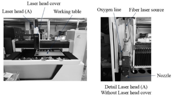
Table 2Specification of laser equipment
Table 2
|
Specification |
Value |
|
Wave length |
1.06 × 10⁻⁴ cm |
|
Machining range |
150 × 300 cm |
|
Max. laser power |
600 W |
|
Max. moving speed |
166.67 cm/sec |
|
Positioning accuracy |
0.003 cm |
|
Repeated positioning accuracy |
0.002 cm |
|
Minimum line width |
0.01 cm |
|
Diameter of focus beam |
85 × 10-4 cm |
2.3 Test jig 제작
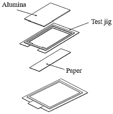
본 실험 간, 시편에 손을 대지 않고 관통 여부를 확인하기 위해 시편의 하단에 종이를 넣을 수 있는 Test Jig를 제작하였다. 시편이 관통되면, 레이저 빔을 맞은 하단의 종이에 구멍이 뚫리고, 이를 통해 다양한 조건 마다 시편의 관통 여부를 확인할 수 있었다. Test Jig에 놓인 시편은
Fig. 1의 Working Table위에 위치한다.
Fig. 2에 Test Jig, 알루미나, 종이의 조립도를 나타내었다.
Fig. 2Test jig set assembly for the first experiment

3. 관통조건 실험, 직교배열표를 적용한 관통 실험
3.1 관통조건 실험 개요 및 조건
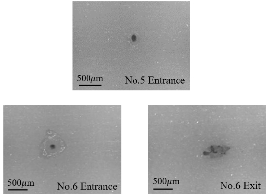
레이저의 1회 발진으로 알루미나를 관통할 수 있는 조건을 찾기 위한 실험을 수행하였다. 초점 위치를 시편 두께의 중간으로 고정하고 산소 압력, 파워 밀도, 조사시간을 조정하였다. 연속파 레이저 에너지는 출력과 조사시간을 곱이며,
Table 3에 1차 실험 조건과 관통여부,
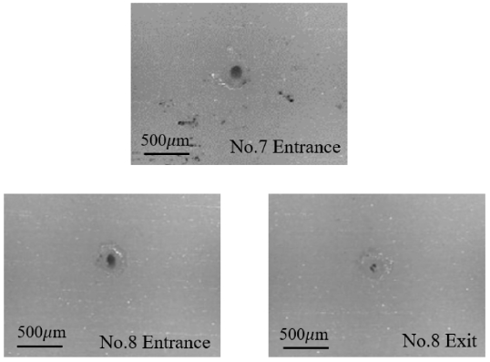
Figs. 3과
4에 5, 6번과 7, 8번 조건에 대한 알루미나 입, 출구 부 사진을 수록하였다.
Table 3First experiment results for combinations of three parameters
Table 3
|
No. |
O2 Pressure
(bar) |
Power density
(W/cm2) |
Duration
(sec) |
Energy
(J) |
Drilled
thru |
|
1 |
3 |
1.8 × 10⁶
|
0.008 |
0.8 |
No |
|
2 |
3 |
3.5 × 10⁶
|
0.018 |
3.6 |
No |
|
3 |
3 |
1.8 × 10⁶
|
0.1 |
10 |
No |
|
4 |
3 |
3.5 × 10⁶
|
0.1 |
20 |
No |
|
5 |
6 |
5.3 × 10⁶
|
0.1 |
30 |
No |
|
6 |
3 |
5.3 × 10⁶
|
0.1 |
30 |
Yes |
|
7 |
3 |
0.9 × 10⁶
|
0.6 |
30 |
No |
|
8 |
3 |
1.8 × 10⁶
|
0.3 |
30 |
Yes |
|
9 |
3 |
5.3 × 10⁶
|
0.1 |
30 |
Yes |
|
10 |
3 |
3.5 × 10⁶
|
0.15 |
30 |
Yes |
|
11 |
3 |
7.0 × 10⁶
|
0.075 |
30 |
Yes |
|
12 |
3 |
8.8 × 10⁶
|
0.06 |
30 |
Yes |
|
13 |
3 |
1.1 × 10⁷
|
0.05 |
30 |
Yes |
Fig. 3No. 5 and No. 6 entrance and exit pictures of the first Experiment

Fig. 4No. 7 and No. 8 entrance and exit pictures of the first Experiment
3.2 관통조건 실험 결과 및 고찰
에너지 조사량이 30 J에 도달할 때, 특정 경우를 제외하면 관통이 이루어 진 것을 알 수 있었다. 5번과 6번 조건을 비교하면, 동일한 파워밀도를 갖는 30 J의 에너지를 조사해도 산소압이 높은 경우에는 관통이 되지 않았다. 이는 높은 산소압 때문에 가공 도중 냉각이 빠르게 일어났기 때문이라고 판단된다.
7번과 8번 조건으로부터, 에너지 조사량이 30 J 이더라도 관통이 되지 않았음을 알 수 있다. 이는 알루미나의 어블레이션을 일으킬 정도로 파워 밀도가 크지 않기 때문이라고 추정된다.
1차 실험을 통하여 약 3 bar의 산소압과 0.035 W/μm 이상의 파워 밀도를 가질 때, 30 J 이상의 에너지를 가하면 알루미나의 관통이 이루어지는 것을 확인하였다.
3.3 직교배열표를 적용한 관통 실험
2차 실험에 적용할 직교배열표 상 제어변수를 초점 위치, 산소압, 파워 밀도, 조사시간으로 선정하였다. 1차 실험 결과를 참고하여 산소압은 3 bar를 기준으로 각각 2 bar, 4 bar로 설정하였다. 파워 밀도는 레이저 장비의 최대값과 중간값으로 설정하였고, 조사 시간은 레이저 에너지 최소값이 30 J을 가지도록 하였다. 레이저가 처음 조사되는 시편의 표면을 상단 부 라고하면, 초점 위치는 두께 방향으로 중간과 하단 부로 설정하였다. 위의 4가지 변수에 대하여 2수준 직교배열표를
Table 5에 수록하였다.
Table 4Two level control factors
Table 4
|
Level |
Focal position,
vertical |
O2 pressure,
(bar) |
Power density
(W/μm2) |
Duration,
(sec) |
|
1 |
Middle of Plate |
2 |
0.053 |
0.1 |
|
2 |
Bottom of plate |
4 |
0.106 |
0.2 |
Table 5L8 orthogonal array for the control variables of Table 4
Table 5
|
Hole No. |
Focal position,
vertical |
O2 pressure,
(bar) |
Power density
(W/cm2) |
Duration,
(sec) |
|
1 |
1 |
1 |
1 |
1 |
|
2 |
1 |
1 |
2 |
2 |
|
3 |
1 |
2 |
1 |
2 |
|
4 |
1 |
2 |
2 |
1 |
|
5 |
2 |
1 |
1 |
2 |
|
6 |
2 |
1 |
2 |
1 |
|
7 |
2 |
2 |
1 |
1 |
|
8 |
2 |
2 |
2 |
2 |
3.4 직교배열표를 적용한 관통 실험 결과 및 고찰
모든 조건에 대하여 관통이 이루어졌다.
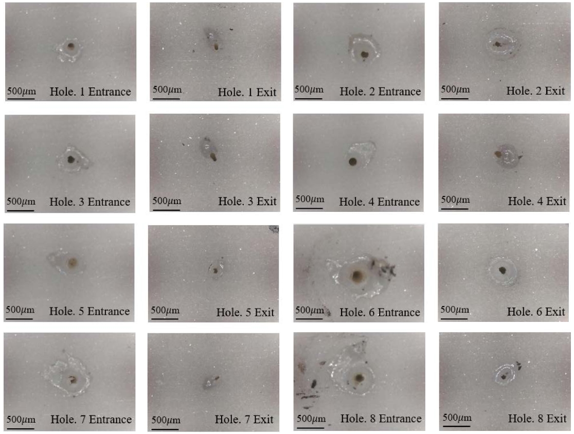
Fig. 5은 8개 관통 구멍의 단면을 나타내며,
Fig. 6은 8개 구멍의 입, 출구 부 사진이다.
Table 5에 8개 구멍의 입구, 중간 및 출구 직경을 수록하였다. 열을 가장 오래 받는 입구 측 직경이 큰 것을 알 수 있다. 가공이 진행되면서 구멍 내부에서 기화된 알루미나가 입구 측으로 나오다가 벽면에 재 응결되기 때문에 내부의 직경이 일정하지 않다고 추정할 수 있다.
Fig. 5Second experiment cross sections of 8 holes
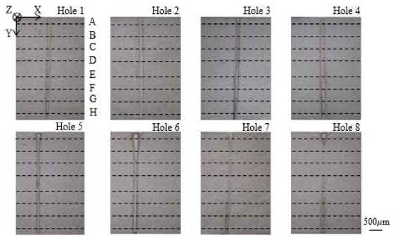
Fig. 6Entrance and exit pictures of 8 holes of the second experiment

Fig. 5에서 단면구간이 휘어져 있고, 일부 구멍은 중간 부분이 막혀 있는 것을 볼 수 있다. 이는 기화된 알루미나가 재 응결하여 구멍 내부에서 난반사가 일어나고, 이 결과 레이저의 조사가 불균일하게 일어난 결과로 추정된다.
4. 관통 구멍의 기하학적 품질 평가
4.1 단면 형상의 스캔 방법
탐침(Stylus)이 달린 접촉식 표면 측정기(DekTakXT, Bruker Co.)를 사용하여
Fig. 5의 X축 방향으로 탐침을 운용하면서 Z축 방향의 표면 좌표를 측정하였다. 각 구멍에 대하여 Y축 방향으로 8개(A, B, C, D, E, F, G, H)의 정해진 위치에서 탐침을 운용하였다. 시편의 입구 및 출구 측 표면 상태에 따라 Y축 상 A와 H의 위치를 다소 조정할 필요가 있었다. 이에 따른 3 종류의 스캔 모드를
Table 6에 수록하였다.
Table 6Dimensions of the 8 holes in Fig. 5
Table 6
Hole
No. |
Entrance diameter
[μm] |
Middle diameter
[μm] |
Exit diameter
[μm] |
|
1 |
128 |
102 |
71 |
|
2 |
153 |
109 |
103 |
|
3 |
128 |
92 |
87 |
|
4 |
177 |
185 |
171 |
|
5 |
221 |
87 |
127 |
|
6 |
260 |
84 |
146 |
|
7 |
172 |
70 |
131 |
|
8 |
231 |
34 |
110 |
4.2 최소 제곱법을 이용한 단면 형상 데이터 분석
전술한 방법으로
Fig. 5 각 단면의 스캔 위치 별 표면 좌표 데이터 세트 (
Xi,
Zi)를 확보하였다. 구멍의 단면 형상을 대표하는 임의의 원의 중심 좌표를 (
XR,
ZR), 반경을
R 이라고 하였다.
좌표 데이터 점 (Xi, Zi)에서 원의 중심 (XR, ZR)까지 거리를 r 이라고 하면, R2과 r2 차이의 제곱근을 오차를 Error라고 하면 다음과 같이 쓸 수 있다.
데이터 개수가 n개 라면,
식(1)의 합은 다음과 같이 표현된다.
식(2)가 최소값을 갖도록 하는 임의의
XR,
ZR,
R 값을 최소 제곱법을 통해 구하면, 각 스캔 위치에서 대표 원 중심의 위치와 직경을 알 수 있다.
구멍의 진직도를 알아보기 위하여 스캔 위치 A의 대표 원 중심에 대한 (B - H) 위치 대표 원 중심의 X 방향 상대적 거리를
Table 7에 수록하였다. 각 스캔 위치에서 대표 원 직경과 가공 목표 직경의 비를
Table 8에 수록하였다.
Table 7Y-axis scan positions A, B, C, D, E, F, G and H in Fig. 5
Table 7
Y-axis position
coordinates,
(μm) |
Mode 1
Hole 1 |
Mode 2
Hole 2, 3, 4, 5 |
Mode 3
Hole 6, 7, 8 |
|
A |
25 |
186 |
25 |
|
B |
625 |
744 |
570 |
|
C |
1225 |
1302 |
1116 |
|
D |
1825 |
1860 |
1661 |
|
E |
2425 |
2419 |
2207 |
|
F |
3025 |
2977 |
2752 |
|
G |
3625 |
3535 |
3298 |
|
H |
3875 |
4000 |
3843 |
Table 8Relative X-axis distance of the hole centers at 8 scan positions A - H with respect to the position A (see Fig. 5), μm
Table 8
|
Hole |
1 |
2 |
3 |
4 |
5 |
6 |
7 |
8 |
Scan
position |
|
A |
0 |
0 |
0 |
0 |
0 |
0 |
0 |
0 |
|
B |
-11 |
+13 |
-3 |
-11 |
-23 |
+17 |
-11 |
-16 |
|
C |
-14 |
+23 |
-4 |
-7 |
-19 |
+5 |
-38 |
-4 |
|
D |
-24 |
+27 |
-8 |
+8 |
-15 |
-6 |
-40 |
-18 |
|
E |
-34 |
+35 |
-37 |
+25 |
-20 |
-6 |
-46 |
-21 |
|
F |
-49 |
+29 |
-46 |
+47 |
-25 |
-10 |
-89 |
-19 |
|
G |
-64 |
+29 |
-76 |
+63 |
-19 |
-15 |
-150 |
-27 |
|
H |
-68 |
+15 |
-77 |
+77 |
-15 |
-18 |
-198 |
-40 |
4.3 구멍의 기하학적 품질 평가
Table 7과
Table 8로부터 두 가지 평가 요소를 선정하였다.
Fig. 5 각 단면의 스캔 위치 A에서 대표 원의 X 축 중심 좌표를
XA, B - H에서 X축 중심 좌표를
Xi (
i = B, C, D, E, F, G, H) 라고 하면, 각 스캔 위치에서
XA와
Xi 거리 차이 합의 평균은 XY 평면에서 입구와 출구의 진직도 오차를 나타낸다. 이를 첫 번째 평가요소
α로 선정하였고, 이는 다음과 같이 쓸 수 있다.
Table 8에서 구멍 가공의 목표 직경(85 μm)을
DT, 각 스캔 위치 A - H에서 추정되는 대표 원의 직경을
Di, (
i = A, B, C, D, E, F, G, H)라고 하였다. 각 스캔 위치에서 대표 원 직경과 목표 직경 차이 합의 평균을 구멍의 가공 정밀도 오차
β라고 하였고, 이는 다음과 같이 표현 된다.
상기 두 가지 요소를 적용하여 가공 된 구멍의 평가를 수행하였다. 구멍이 목표 직경을 갖으면서 관통 구간 전체에 수직으로 가공 될수록
α +
β의 합이 최소가 된다. 따라서 두 요소의 합이 최소 값을 가지는 단면이 가공 결과가 가장 좋다고 판단하였다.
Table 9에 구멍 가공 품질 평가 결과를 수록하였다.
Table 9Ratio of representative diameter and target diameter
Table 9
|
Hole |
1 |
2 |
3 |
4 |
5 |
6 |
7 |
8 |
Scan
position |
|
A |
1.5 |
1.8 |
1.5 |
2.0 |
2.6 |
3.1 |
2.0 |
3.0 |
|
B |
1.4 |
1.7 |
1.3 |
1.7 |
1.9 |
2.7 |
1.1 |
0.2 |
|
C |
1.2 |
1.7 |
1.2 |
1.8 |
1.4 |
1.4 |
0.9 |
0.1 |
|
D |
1.3 |
1.7 |
1.1 |
2.5 |
1.1 |
1.2 |
0.4 |
0.8 |
|
E |
1.3 |
1.6 |
1.1 |
2.5 |
1.4 |
1.0 |
0.8 |
1.3 |
|
F |
1.1 |
1.5 |
1.0 |
2.3 |
1.9 |
1.0 |
1.1 |
1.5 |
|
G |
1.1 |
1.4 |
1.0 |
1.9 |
1.9 |
1.5 |
1.3 |
1.4 |
|
H |
0.8 |
1.2 |
1.0 |
2.0 |
1.9 |
1.7 |
1.5 |
1.3 |
Table 10Evaluation of 8 holes with respect to two factors, μm
Table 10
|
Hole No. |
α
|
β
|
α + β
|
|
1 |
38 |
22 |
60 |
|
2 |
24 |
50 |
74 |
|
3 |
36 |
12 |
48 |
|
4 |
34 |
92 |
126 |
|
5 |
19 |
65 |
84 |
|
6 |
11 |
59 |
70 |
|
7 |
82 |
31 |
113 |
|
8 |
21 |
56 |
77 |
5. 제어변수 분석
5.1 민감도, 교호작용 그래프
Table 4와
Table 5에 따라 실험을 수행하고, 각 제어 변수가 구멍의 기하학적 품질에 미치는 영향을 분석한 민감도 그래프를
Fig. 7에 도시하였다.
Fig. 7 가로 축 상 7개 변수에 대하여 a는 초점 위치, b는 산소압, c는 파워 밀도, d는 조사 시간이며, 나머지는 변수 간의 교호작용을 나타낸다.
Fig. 7에서 기울기가 클수록 가공 결과에 미치는 영향이 크며, 3.3 절에서 언급한 대로
α +
β의 값이 작을수록 좋다.
Fig. 8은 초점 위치가 레벨 1에서 2로 갈 때, 파워 밀도와의 교호작용을 도시한 것이다.
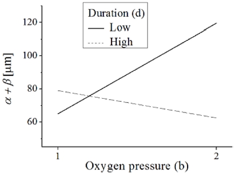
Fig. 9는 산소압이 레벨 1에서 2로 변화할 때, 레이저 조사시간 과의 교호작용을 나타낸 것이다.
Fig. 7Sensitivity analysis of control variables
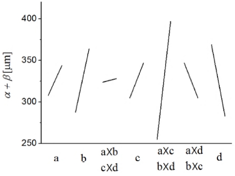
Fig. 8Interaction analysis between focal position and laser power density
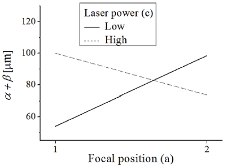
Fig. 9Interaction analysis between oxygen pressure and duration
5.2 가공 조건 도출
Fig. 7으로부터 조사시간(d), 산소압(b), 파워 밀도(c), 초점 위치(a) 순으로 가공 결과에 미치는 영향이 크다는 것을 알 수 있다. 그러나 5번째 교호작용 변수의 기울기가 가장 크기 때문에 초점 위치와 파워 밀도, 산소압과 조사시간 사이에 강한 교호작용이 존재함을 알 수 있다. 교호작용 그래프
Figs. 8과
9로부터
α +
β가 최소 값을 갖는 제어변수 조합은 a1, b2, c1, d2 (초점 위치 중간, 산소압 4 bar, 파워 밀도 0.053W/μm, 조사시간 0.2 sec) 임을 알 수 있었다.
위 제어변수 조합은 전술한 2차실험 8가지 조건 중 3번 가공조건에 해당하며,
Table 9에서 알 수 있듯 3번 구멍의 평가 결과가 가장 좋았다.
6. 결론
레이저에 의한 알루미나의 용융 및 증발에 의하여 구멍 가공이 이루어지며, 구멍 내부 알루미나 증기가 입구로 나오는 중 구멍 벽면에 재 응결되기 때문에 내부 직경이 일정하지 않다고 볼 수 있다. 구멍 벽면에 생긴 재 응결 층으로 인해 내부에서 난반사가 일어나고, 이는 레이저 조사량을 불 균일하게 만들기 때문에 구멍의 진직도를 떨어뜨린다고 추정하였다.
본 연구에서는 Nd:YAG 연속파 레이저를 사용한 알루미나 판재의 미세구멍 가공에서 제어변수들이 구멍 가공 결과에 미치는 영향을 연구하였다. 알루미나 드릴링을 위한 최소 요구 파워 밀도는 약 0.035 W/μm2이고, 30 J 이상의 에너지를 가해야 관통이 이루어졌다. 이러한 조건을 충족하더라도 산소압이 지나치게 높으면 관통이 되지 않았다. 이는 산소압이 강할수록 레이저 가공 중에 냉각이 빨리 일어나기 때문이라고 판단된다. 제어변수 중에서 조사시간과 산소압이 구멍 가공 결과에 주로 영향을 미치며, 민감도 분석과 교호작용을 고려하여 도출 된 제어 변수 조합은 초점위치 중간, 산소압 4 bar, 파워 밀도 0.053 W/μm2, 조사 시간 0.2 sec이다. 레이저 가공 간 제어변수들을 조정할 때, 초점위치와 레이저 파워밀도, 산소압과 조사시간 사이에 강한 교호작용이 존재하므로 이를 고려하여야 한다.
REFERENCES
- 1.
Lee, S.-M., Woo, J.-S., Lee, M.-S., “Femtosecond Laser Micromaching in Alumina Ceramic,” Journal of the Korean Society of Laser Processing, pp.121-124, 2008.
- 2.
Kim, B. Y. and Lee, K. S., “A Study on the Microhole Machining Characteristics of the Al2O3 Ceramics using Excimer Laser,” Proc. of KSPE Autumn conference, pp. 1072-1075, 2001.
- 3.
Youn, H. J., Lim, S. J., Lee, D. J., “A Study on the Micro Hole Machining of Al2O3 Ceramics,” Proc. of the Korean society of machine tool engineers Autumn conference, pp. 37-42, 1997.
- 4.
Paik, B. M., Lee, K. S., “A study on the Laser Beam Characteristics during Al2O3 Ceramic Microhole Machining,” Proc. of KSPE Spring Conference, pp. 1056-1059, 2001.
- 5.
Kuar, A., Acherjee, B., Ganguly, D., and Mitra, S., “Optimization of ND: YAG Laser Parameters for Microdrilling of Alumina with Multiquality Characteristics Via Grey–Taguchi Method,” Journal of Materials and Manufacturing Process, Vol. 27, No. 3, pp. 329-336, 2012.
10.1080/10426914.2011.585493
- 6.
Shin, J. H., Kim, T. H., Chung, J. H., Noh, C. R., and Kim, K. I., “The Study of Drilling of Alumina and Polymer Materials by Laser Beam,” Journal of the Korean Society of Laser Processing, Vol. 4, No. 3, 2001.
- 7.
Kim, B. Y. and Lee, K. S., “A Study of Machining Characteristics Effecting on Laser Focusing Position in the Ceramics Microhole Machining,” Proc. of KSME Conference, Vol. 1, No. 3, 2001.
- 8.
Youn, H., Lee, K., and Lee, D., “The Influence of Processing Condition and Assistance Gas in Microhole Machining of Al2O3 Ceramics,” Journal of the Korean Sociene Tool Engineers, Vol. 8, No. 5, pp. 115-120, 2003.
Biography
- Dae Hea
M.E. in the Department of Mechanical Engineering, Korea University. Staff/Pohang Steel Works, wire rod rolling mill department. His research interest is in the field of rolling mill technology.
- Kwon Hee Kim
Professor in the Department of Mechanical Engineering, Korea University. His research interest is in the creative design of mechanical systems and commercial products.
- Doo Hyun Cho
Ph.D. candidate in the Department of Mechanical Engineering, Korea University. His research interest is in the design and development of precision machines.
- Kwang Joon Kim
Ph.D. candidate in the Department of Mechanical Engineering, Korea University. His research interest is in the production technology including laser drilling and deburring.