ABSTRACT
Fluid Catalytic Cracking (FCC) Unit is a large-pressure vessel that converts heavy crude oil, which cannot be distilled, into light crude oil. With the growing interest in renewable energy sources due to environmental regulations, various studies investigating FCC Units are ongoing. The catalytic reactor in FCC Unit is a large structure that generates prolonged high pressure, leading to changes in the properties of the material during operation. Therefore, stress analysis must be conducted based on the application of the actual mechanical properties. In cylindrical thin structures such as the FCC reactor, a tensile test is difficult to perform, warranting the need for Shear Punch (SP) test that uses a small specimen. The properties were utilized in finite element analysis. To determine the boundary and load conditions needed for stress analysis, the operational conditions of the reactor and the conditions for internal pressure of ASME Code regulation were used to evaluate the stress.
-
KEYWORDS: Fluid catalytic cracking reactor, Shear punch test, Finite element analysis, Stress analysis, Safety assessment, ASME Code
-
KEYWORDS: 유동상 촉매 분해 반응기, 전단 펀치 시험, 유한 요소 해석, 응력 분석, 안전성 평가, ASME 코드
1. Introduction
With the improved living standards and industrial development worldwide, the demand for energy resources is on a continued rise. Due to limited resources, shortage of energy resource has become a serious issue. Moreover, with environmental regulations, interest in renewable energy and Fluid Catalytic Cracking (FCC) Unit, which is a production facility for renewable energy, has also grown. FCC Unit decomposes medium crude oil and is a large-scale pressure vessel to convert medium crude oil such as Bunker C oil where distillation is no longer possible into light crude oil. FCC Unit consists of a reactor and regenerator. The reactor where the catalyst reaction occurs is operated in high temperature and high pressure. When it is operated for a long time in such condition, FCC caused safety issues due to the change of material properties. Therefore, when designing a FCC Reactor, safety evaluation of the initial material properties as well as the material properties after long-term usage becomes important.
Generally the uniaxial tensile test through the tensile testing machine can be useful in acquiring the material properties, but it is difficult to apply this method to the FCC Reactor in a cylinder structure. The Shear Punch (SP) test, compared to the test recommended by the standards of the tensile test, uses a miniature specimen. It is useful to evaluate the strength of local sites of a structure or specific binding parts from the load-displacement curve to the stress-strain curve. In addition, it is also used to evaluate the life expectancy of the structure by comparing the material properties of the structure before usage and after long-term usage. Hankin et al. evaluated the shear strength of the austenite alloy using a punch in the shape of a cylinder.
1 Leon et al. applied the evaluation formula proposed by Hankin and researchers on the strength evaluation of composite materials.
2 The finite element analysis (FEA) for a structure is used to evaluate the stress and the structure. This test was used for cost and time-efficient safety assessments. Kim et al. also studied the safety of pressure vessels of composite material for vehicles by applying the finite element analysis.
3
This paper seeks to learn, through an SP test, the initial material properties of the FCC Reactor that could change during continued operation due to high temperature and high pressure. This test method gives the load-displacement curve and then calculated the stress-strain curve. Through the Stress-strain curve, the ultimate tensile strength (σt) was calculated as well as the elasticity coefficient (E) and yield strength (σγ). By applying the acquired material properties and considering the internal pressure and the weight of the external vessel, a structural analysis of the FCC reactor was performed. The analysis results evaluated the structural safety of the ASME Code.
2. Preparation of Test Specimens and Test Methods
In general, the material properties for the manufacturing of a pressure vessel are shown in
Table 1. The materials used for the SP test is the same material as the FCC reactor. As seen in
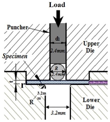
Figs. 1 and
2, the specimen was inserted between the upper die and the lower die and a SP test jig was manufactured using a punch and steel ball. The test was conducted using the SP test equipment.
Table 1 Mechanical properties of ASTM A53 Gr. B
Table 1
|
Material |
Yield
strength |
Tensile
strength |
Modulus of
elasticity |
|
ASTM A53 Gr. B |
240 MPa |
415 MPa |
200 GPa |
Fig. 1 Experiment setup of SP test
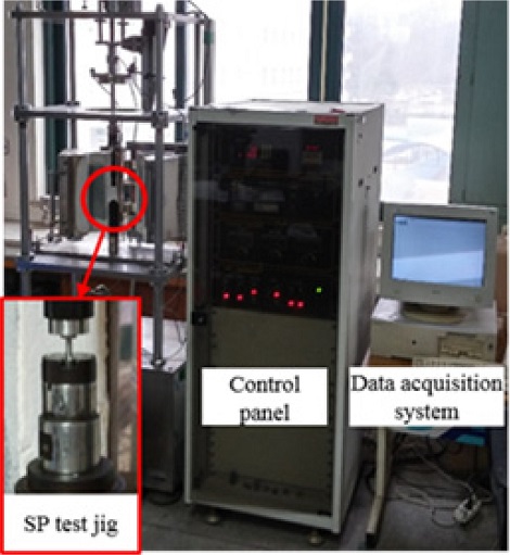
Fig. 2 Schematic diagram of the detailed SP test

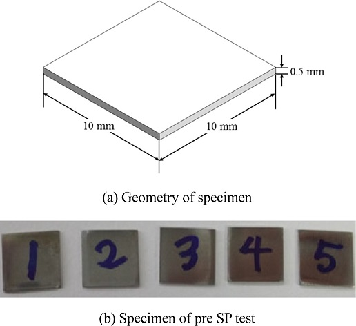
The test was conducted with five specimen of the same size, and the geometry of specimen are shown in
Fig. 3.
Fig. 3 Five specimens of the SP test

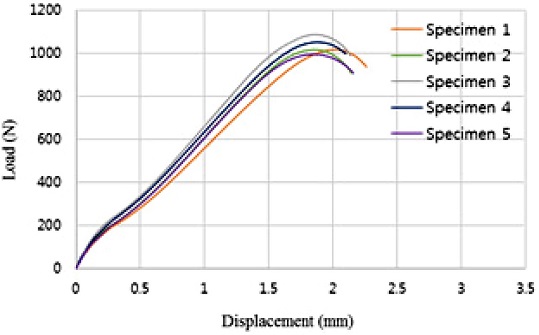
The applied load and the central displacement of the specimen acquired in the SP test are shown as the load-displacement curve in
Fig. 4. The Stress-strain curve is represented based on the load-displacement curve, and the ultimate stress (
σu) was calculated as 457.9MPa.
4,5
Fig. 4 Load-displacement curve for SP test specimen

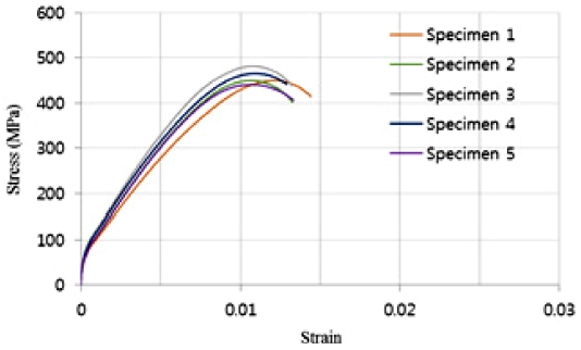
Using the slope of the linear section in the Stress-strain curve’s elasticity field in
Fig. 5, the elasticity value (
E) was calculated as 186.4 MPa. By offsetting the slope by 0.2%, the yield strength was calculated as 211.9 MPa. The test result showed in
Table 2 about 10% less than the material properties in
Table 1 used in FCC reactor pressure vessels due to different environmental condition.
Fig. 5 Stress-strain curve for SP test specimen

Table 2 Mechanical properties by SP test specimen
Table 2
|
Yield
strength |
Ultimate
strength |
Modulus of
elasticity |
|
Specimen 1 |
202.76 |
450.58 |
151.32 |
|
Specimen 2 |
212.72 |
450.14 |
206.20 |
|
Specimen 3 |
222.25 |
481.77 |
209.137 |
|
Specimen 4 |
221.82 |
465.74 |
185.98 |
|
Specimen 5 |
200.16 |
441.48 |
179.43 |
|
Mean value |
211.9 |
457.9 |
186.4 |
3. Structural Analysis of FCC Reactor
3.1 Modeling and Analysis Method
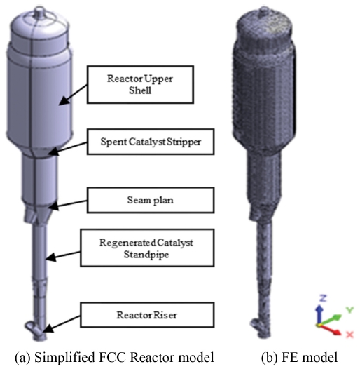
In fact, in the case FCC Units, the height is about 53 m and the weight is about 680 ton, making it a huge and complex structure. Therefore it is necessary to simplify the modeling, otherwise it would take too much time. To conduct a stress analysis of the external vessel in the FCC Reactor, a simplification of the external attachments and internal structure was conducted and modeled as seen in
Fig. 6(a). CATIA V5 3D modeling program was used. For analysis, the commercial (FEA) software midas NFX program was used to make the finite element model as seen in
Fig. 6(b). For the material properties of the structure, the value acquired from the SP test was applied. For the mesh type, a hybrid mesh was used. The number of nodes was 60,135 and the number of elements was 67,846.
Fig. 6Simplified FCC Reactor model and FE model
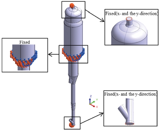
From
Fig. 7, the boundary condition constrained the lower and the upper section of the FCC reactor in the x-axis. The boundary condition also constrained the rotation at the x- and the z-axis. The boundary condition constrained the translation and the rotation for all three axis (x, y, and z) at all lower part of the spent catalyst stripper. The load condition included an internal pressure of 0.45 MPa and external vessel’s weight.
Fig. 7Boundary condition of FCC reactor
3.2 Stress Analysis
The result of the structural analysis shows that the largest stress was, as seen in
Fig. 8, occurring at the nozzle part of the seam plan. It is difficult to conclude the overall stress of the structure from the analysis result. Therefore, as seen in
Fig. 9, using the stress linearization of the midas NFX, the result was analyzed.
Fig. 8Result of structural analysis in FCC Reactor
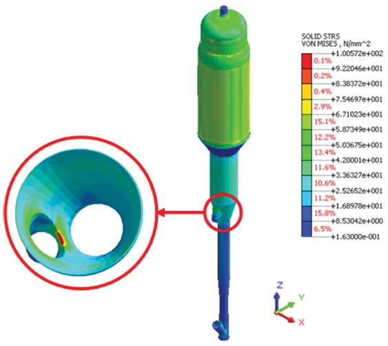
Fig. 9Result of stress linearization analysis
4. Safety assessment by ASME code
Across different countries, the standards for the design production, testing and installation of pressure vessels is used by ASME, BS, DIN, and JIS. At present, the most widely used standard is the ASME. The FCC reactor vessel is designed using the ASME code section VIII div.2 and the analysis was performed using Finite Element Method (FEM) to evaluate the structural safety of the pressure condition. Within the ASME, section VIII Div.1 and Div.2 are applied to the design and manufacturing of pressure vessels and used for assessing structural safety.
4.1 Allowable Stress
In ASME Section VIII, the allowable stress is defined by different creep temperature. When lower than creep temperature, the maximum allowable stress is the lowest of the stress values, respectively and criteria for establishing allowable stress values is shown
Table 3.
Table 3Criteria for establishing allowable stress values
Table 3
|
Stress value |
ASME Section
VIII Div.1 |
1) The specified minimum tensile strength divided by 3.5
2) Two-thirds of the specified minimum yield strength |
ASME Section
VIII Div.2 |
1) The one-third of the specified minimum tensile strength
2) Two-thirds of the specified minimum yield strength |
Within the creep temperature range, the creep fracture strength of 100,000 hours is defined as the allowable stress.
6
The FCC Unit had a weight of about 680 ton, and the ASME Section VIII Div.2 was applied to allowable stress by dividing it into membrane stress (
Pm) and bending stress (
Pb) specified, so the results are compared using Stress Classification Line (SCL) function of the analysis program. In ASME Section VIII Div.2 where it discusses the design of a pressure vessel and perform the stress analysis by FEM the correlation with allowable stress is defined as follows.
7
1) General primary membrane stress
2) Local primary membrane stress
3) Local primary membrane stress + Primary bending stress
4) Primary stress intensity + Secondary stress intensity
5) Primary stress intensity + Secondary stress intensity + Peak stress intensity is used to forecast the fatigue life expectancy under the conditions of the operation weight.
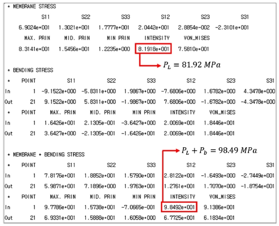
One third of the ultimate tensile strength was 152.63 MPa and two thirds of yield strength was 141.27 MPa. Therefore the minimum of the allowable stress was 141.27 MPa. The primary membrane stress (
PL) of the nozzle in the seam plan where the maximum stress occurred was 81.92 MPa, about 39% of the 1.5 times of allowable stress which is 211.91 MPa. The primary membrane stress (
PL) plus primary bending stress (
Pb) was 98.49 MPa, about 46% of the 1.5 times of allowable stress which is 211.91 MPa. The results of the analysis were compared with the stress classification line method to evaluate the safety of the reactor. As a result of the evaluation, it was lower than the allowable stress of ASME Code Section VIII div.2 in
Table 4.
Table 4Stress evaluation of stress linearization
Table 4
|
PL (1.5 × S) |
PL + Pb (1.5 × S) |
Result |
|
SCL |
Actual |
Allowable |
Actual |
Allowable |
OK |
|
81.92 |
211.91 |
98.49 |
211.91 |
5. Conclusions
In this study, a SP test was conducted on the material of the FCC Reactor whose material properties could change due to high temperature and high pressure over a long time. The initial material properties are acquired and applied to the FEA. The analysis result was applied to the ASME Section VIII Div.2 applied to evaluate the safety. The findings can be summarized as follows.
(1) The material properties of the material generally used in the production of pressure vessels were applied to conduct a structural analysis and verified that the maximum stress occurs at the nozzle of the seam plan.
(2) Through the SP test, the initial material properties of the Reactor was acquired and applied to the FEA. Through the linearization of stress, the stress was analyzed.
(3) ASME Section VIII Div.2 was applied to the results of the FEA. The FCC Reactor was evaluated to be structurally safe under the conditions of the external vessel’s gravity load and the internal pressure load.
(4) For the material of standardized structures and processed standardized structures, the physical properties were acquired. The method of applying the ASME code to the results of the FEA to evaluate the structural safety was proposed.
ACKNOWLEDGMENTS
This paper was presented at ISGMA 2016
This research was supported by Basic Science Research Program through the National Research Foundation of Korea (NRF) funded by the Ministry of Education, Science and Technology (No.2014R1A1A4A01008713).
REFERENCES
- 1.
Hankin, G., Toloczko, M., Hamilton, M., Garner, F., and Faulkner, R., “Shear Punch Testing of 59Ni Isotopically-Doped Model Austenitic Alloys After Irradiation in FFTF at Different He/dpa Ratios,” Journal of Nuclear Materials, Vols. 258-263, No. 2 pp. 1657-1663, 1998.
10.1016/S0022-3115(98)00204-9
- 2.
Leon, C. and Drew, R., “Small Punch Testing for Assessing the Tensile Strength of Gradient Al/Ni–SiC Composites,” Materials Letters, Vol. 56, No. 5, pp. 812-816, 2002.
10.1016/S0167-577X(02)00619-5
- 3.
Kim, C.-K. and Kim, D.-H., “A Safety Study on the Stress Characteristics of a Composite Pressure Cylinder for a Use of 70MPa Hydrogen Gas Vehicle,” Journal of The Korean Society of Manufacturing Technology Engineers, Vol. 21, No. 1, pp. 1-6, 2012.
10.7735/ksmte.2012.21.1.001
- 4.
Baek, S.-S., Park, J.-H., and Yu, H.-S., “Creep Characterization of 9Cr1Mo Steel Used in Super Critical Power Plant by Conversion of Stress and Strain for SP-Creep Test,” Transactions of the Korean Society of Mechanical Engineers A, Vol. 30, No. 9, pp. 1034-1040, 2006.
10.3795/KSME-A.2006.30.9.1034
- 5.
You, H., Lim, J.-K., and Chung, S.-H., “A Study on the Stress Corrosion Cracking Evaluation for Weld Joint of Steel by Using Miniaturized Small Specimen,” Journal of Korean Welding Society, Vol. 12, No. 4, pp. 63-75, 1994.
- 6.
Kim, T., “Analysis of Structural Design Criteria of Pressure Vessels based on ASME Section VIII,” Proc. of the Korean Society of Mechanical Engineers Autumn conference, pp. 98-107, 2002.
- 7.
American Society of Mechanical Engineers “Rules for Construction of Pressure Vessels,” ASME Boiler and Pressure Vessel Committee, 2013.
Biography
- Dae Su Kim
M.Sc. Department of Mechanical Design Engineering, Chonbuk University. His research interest is Mechanism Machine Design.
- Hee Yong Kang
Professor in the Department of Mechanical Design Engineering, Chonbuk University. His research interest is Mechanism Machine Design.
- Jun Young Yim
M.Sc. Department of Mechanical Design Engineering, Chonbuk University. His research interest is Mechanism Machine Design.
- Sung Mo Yang
Professor in the Department of Mechanical System Engineering, Chonbuk University. His research interest is Mechanical Design.