ABSTRACT
The gear ratio variable topology of a magnetic gear with an integrated harmonic modulator is analyzed using a magnetic permeance model. A dynamic characteristic equation is derived in consideration of the gear ratio between each layer constituting the magnetic gear: the driving side, the driven side, and the control side layer. Based on derived transfer function, the frequency characteristic between driving torque and angular speed of the driving side is analyzed. Theoretic model is compared with an experimental test result using the in-house dynamometer. In the general magnetic gears, the gear ratio is variable so that speed between each layer decelerates with gear ratio, but transmission torque is constant regardless of gear ratio. In this study, these characteristics are also verified through theoretical methods and experimental results, respectively.
-
KEYWORDS: Dynamic characteristic, Harmonic frequency analysis, Magnetic gear, Noncontact power transmission, Variable gear ratio
-
KEYWORDS: 동특성, 고조파 분석, 마그네틱 기어, 비접촉 동력전달, 가변 기어비
1. 서론
원주방향을 따라 정렬된, 래디알 방향으로 교번 자화된 영구자석(이하 PM) 레이어의 극 성분을 자기적으로 필터링하여 이와 마주한 또 다른 PM 레이어의 극 성분에 동기화시켜 동력 전달을 하는 장치인 마그네틱 기어(Magnetic Gear, 이하 MG)는 기어 치(Tooth)의 기계적인 접촉없이 동력 전달이 가능하기 때문에 유지 보수 측면에서 큰 이점이 있고 따라서 지속적인 유지 보수가 난이한 응용 분야로의 적용이 모색되어왔다.
1-3 단순히 기계식 기어치를 PM으로 변경하여 반도체 라인과 같은 청정 환경에 적용하려는 목적의 초기 모델
4과 달리 현재 MG는 하이브리드 자동차나 전기 자동차의 파워 트레인을 구성하는 인휠 모터용 감속기로 개발이 진행되고 있는데
5,6 이는 MG의 토크 전달 밀도가 기계식 기어의 토크 전달 밀도에 필적할 정도로 성능 개선이 진행되고 있기 때문이다.
7 특히, MG는 가감속 장치뿐만 아니라 모터와 결합한 고토크 모터 형태로도 연구 개발이 진행되고 있다.
8
MG는 이를 구성하는 PM레이어의 극수(Pole Number)에 따라 고정된 기어 비(Gear Ratio)를 갖는 것이 일반적이나 특정 레이어를 회전시키면 기어 비를 가변시킬 수 있다고 알려져 있으며
9 이는 해당 토폴러지를 통해 이해할 수 있다. 그러나 MG의 공극 자기장과 맥스웰 방정식을 통한 가변 기어비 구현에 대한 이론적근거 제시
6외에 이러한 가변 기어비 MG의 제특성에 관한 상세한 연구 결과는 보고된 바가 없다. 이에 본 논문에서는 마그네틱 퍼미언스 모델을 기초로 동 시스템에 대한 기어비 가변 특성의 직관적인 이론적 근거를 제시하고 라플라스 영역에서의 전달함수를 이용하여 시스템의 주파수 응답 특성을 분석한다. 유도된 동특성 모델은 제작된 인하우스 동력계를 이용한 응답 시험 결과와 비교되어 그 타당성이 입증된다. 특히, 기어 비가 가변됨에도 불구하고 MG의 전달 토크 비는 구성 요소의 극수 비에 의해 결정된 바 그대로 변함이 없는데 이를 이론적으로, 실험적으로 검증한다.
2. 마그네틱 기어의 기어비 가변 토폴러지
원주 방향을 따라 놓인 모든 PM이 토크 발생에 기여하는
Fig. 1과 같은 MG는 PM 레이어 사이의 고조파 조절기(Harmonic Modulator, 이하 HM)라 부르는 간헐적 강자성 치에 의한 자기 필터링 현상을 이용하는 시스템이다. 본 장에서는 기존의 로렌쯔 혹은 맥스웰 방정식과 달리
2 자기 퍼미언스를 이용한 MG에 대한 이론 모델을 논의한다.
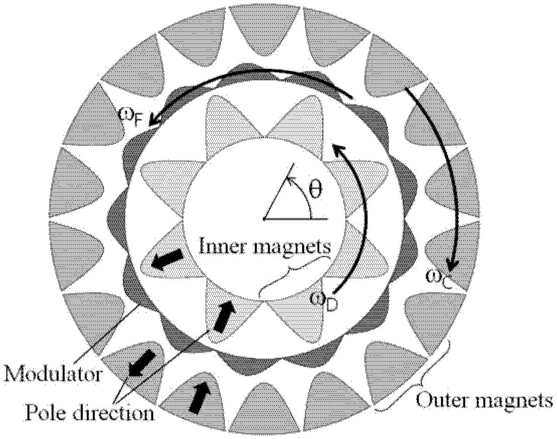
Fig. 1 Ideal concept diagram showing components and primary variables of the magnetic gear

이상적인 MG의 개념도를 묘사한
Fig. 1에서 내측 PM, HM, 외측 PM을 각각 하첨자 D, F, C로 설정하고 N을 각 요소의 극수(Pole Number)라 할 때
ωD로 회전하는 내측 PM 레이어 의한 기자력(Magnetomotive Force)과
ωF로 회전하는 HM의 퍼미언스(Permeance)는
식(1),
식(2)와 같다.
여기에서
Γ0는 PM의 자기 강도와 형상에 의해 결정되는 기자력 계수를 그리고
P0와
Ph는 HM의 모듈 형상과 재질에 의해 결정되는 퍼미언스 계수를 나타내는데 그림에서와 같이 HM이 조화 함수 형상을 갖기 때문에 퍼미언스 역시
식(2)와 같은 식으로 모델링할 수 있다. 특히, 각 구성 요소는 이상적인 모델로 가정했으므로
식(1),
식(2)에서 주극의 고조파는 고려할 필요가 없다.
식(2)를 전개하면
식(3)과 같이 정리된다.
식(1)의 기자력은 HM을 통해 자기적으로 필터링되는데 HM 외측의 자기 플럭스 Y는
Ψ =
Γ ×
P의 관계를 고려하면
식(1)과
식(3)으로부터
식(4)와 같이 계산된다.
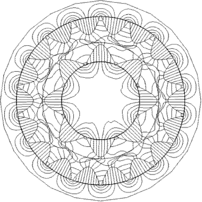
Fig. 2는 유한요소 해석 툴을 활용하여 얻어진, MG를 구성하는 자기 요소간의 자기 플럭스 라인을 묘사하는 그림인데 내측 PM의 일부 자기장만이 필터링되어 외측 PM과 자기 결합하는 것을 확인할 수 있다. 이는
식(4)를 통해 설명이 가능한데 HM 외측 자속의 주극은 각각
ND,
NF +
ND,
NF −
ND이고 따라서 이중에서 내측 PM의 주극인
ND를 제외한 나머지 두 개의 주극과 외측 PM의 극수
NC를 동일하게 설정하면 내, 외측 PM은 일정한 비율로 가, 감속되고 회전한다. 만약, 주극 성분 중
NF −
ND에 외측 PM을 동기화시키면
Fig. 2 Magnetic flux line describing magnetic filtering through the harmonic modulator of magnetic field by inner PM array
이고 따라서 내측 PM, HM의 속도와 외측 속도는
식(4)의 마지막 항을 참조하면
식(6)과 같은 관계를 갖는다.
전술한 이론 모델의 검증을 위해
Table 1에 주어진 제원을 갖는 MG에 대한 유한요소해석을 수행하여 그 결과를
Figs. 3에서
6에 나타내었다.
Table 1의 제원은 3장에서 논의되는 MG 실험장치의 제원이며 내, 외측 PM의 극수가 각각 4, 9이므로 내측이 구동축 즉, 고속축이 된다. 4극쌍의 내측 PM에 의한 자기장을 13극의 HM으로 필터링할 때 HM 외측의 원주방향을 따라 자기장을 구하면
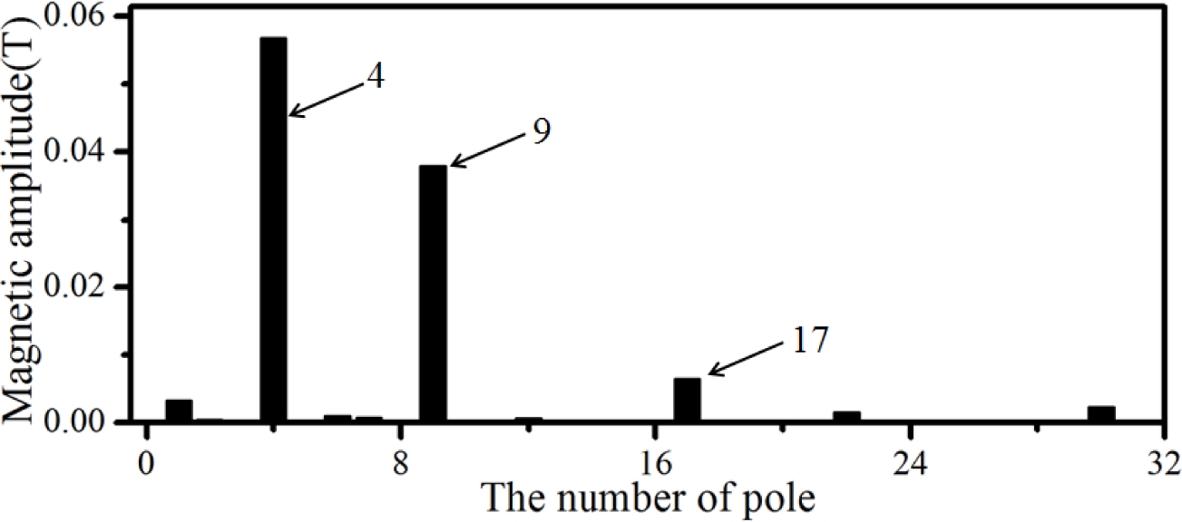
Fig. 3과 같다. 90도 간격의 주기성과 함께 점선으로 표시한 9극의 성분이 현저한 것을 확인할 수 있는데 이러한 결과는 공극 자기장을 고조파 분석한
Fig. 4를 통해 더욱 명확하게 알 수 있다. 해당 선도에서 4극의 주성분과 함께 4극과 13극의 차인 9의 성분 그리고 4극과 13극의 합인 17극의 성분이 순차적인 강도로 나타난 것을 알 수 있는데 이는
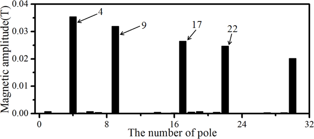
식(4)에 제시된 세 개의 주성분에 해당한다. 이와 반대로 9극의 외측 PM에 의한 자기장이 HM을 통해 필터링될 때 HM 내측의 자기장 분포를
Fig. 5에 그리고 해당 자기장의 고조파 분석 결과를
Fig. 6에 각각 제시하였다. 외측 PM의 9극 주성분과 HM 극수 13극과의 차에 해당하는 4극 성분 그리고 합에 해당하는 22극 성분이 현저하게 나타난 것을 알 수 있는데 이외에 필터링된 4극 성분과 HM간의 결합으로 인한 17극의 고조파 성분 역시 확인할 수 있다.
Table 1 Specifications of the magnet gear used in FEM analysis
Table 1
|
Contents |
Specification |
Material |
|
Inner PM |
Inner, outer radius : 19, 31 mm
Length : 60 mm
Pole number : 4(ND) |
NdFeB
(Nd35) |
|
Modulator |
Inner, outer radius : 32.5, 36.5 mm
Length : 60 mm
Pole number : 13(NF) |
50PN590
(Lamination Steel) |
|
Outer PM |
Inner, outer radius : 38, 50 mm
Length : 60 mm
Pole number : 9(NC) |
NdFeB
(Nd35) |
Fig. 3 Magnetic field distribution at outer air-gap of the harmonic modulator by inner PM array
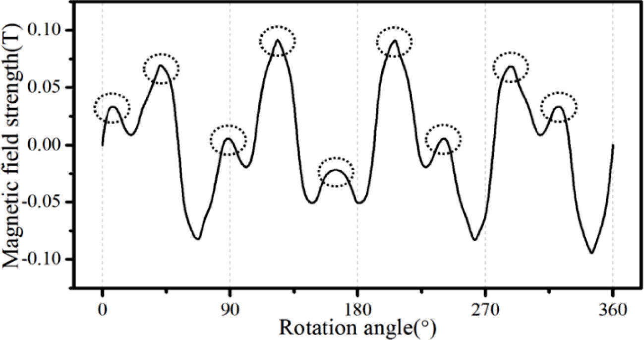
Fig. 4 A harmonic frequency analysis of the circumferential magnetic field given in Fig. 3

Fig. 5 Magnetic field distribution at inner air-gap of the harmonic modulator by outer PM array
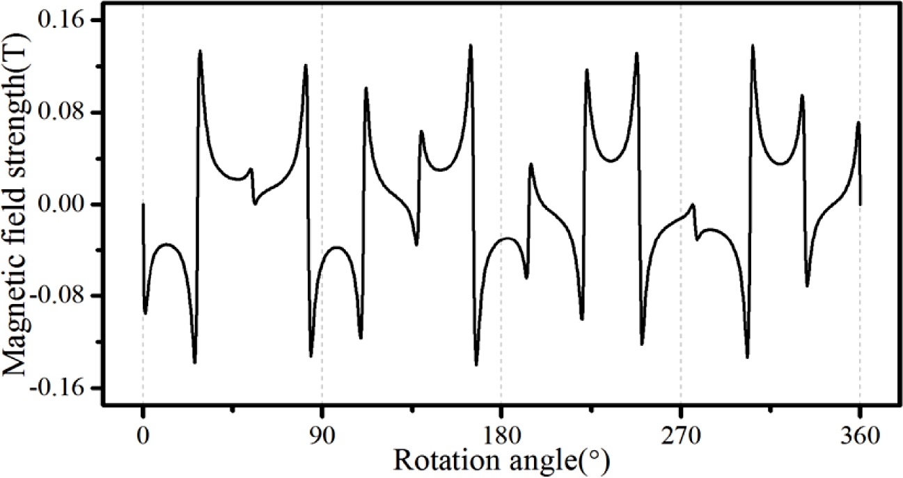
Fig. 6 A harmonic frequency analysis of the circumferential magnetic field given in Fig. 5
일반적으로 MG는 감속 장치로 사용되는데 종동축 즉, 출력축을 HM으로 설정하면 외측 PM은 고정(
ωC= 0)되고 따라서
ωD와
ωF의 감속비는
식(6)으로부터
ND/
NF임을 알 수 있고 토크는 이의 역수만큼 확대된다. 이와 대비되어 출력축을 외측 PM으로 설정하면 HM은 고정되고 마찬가지로
ωD와
ωC의 감속비는
ND/
NC가 된다. 이 때, 특정 레이어를 고정시키지 않고 서로 연계시켜 회전시키면 상기 감속비를 연속적으로 가변시키는 것이 가능하다. 즉, 입력축을 내측 PM으로 하고 출력축을 HM으로 설정할 때
식(6)의 관계식이 성립하도록 외측 PM의 속도
ωC를 조절하면 감속비는 가변되며 HM의 출력 속도는
식(7)을 통해 결정된다.
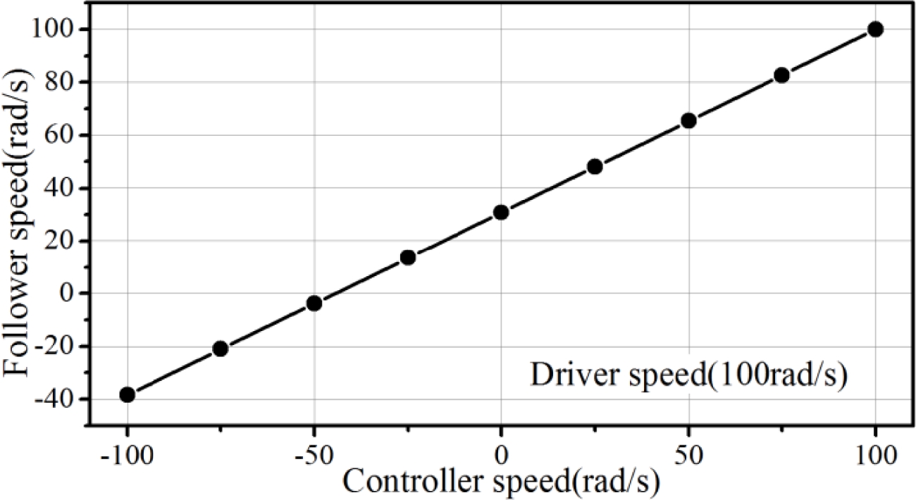
Table 1에 주어진 제원을 이용하여 입력축 속도가 100 rad/s로 고정되었을 때 외측 PM의 속도
ωC에 따른 출력축 속도
ωF의 변화 선도를
Fig. 7에 나타내었다.
ωC가 변함에 따라 출력축 속도가 연속적으로 변화되는 것을 확인할 수 있는데 -100 rad/s일 때 감속비는 대략 1:-0.4이고 100 rad/s일 때는 1:1이 된다. 그림에서 y축이 0인 경우는 외측 PM이 출력축이 되는 일반적인 MG이다.
Fig. 7 Speed variation of HM according to the outer PM speed, under the inner PM rotating constant

3. 기어비 가변에 따른 시스템 동특성
전장에서 논의한 것처럼 기어비가 가변되는 MG는 세 개의 로터가 모두 회전하는 3관성 시스템이다. 내측 PM, HM, 외측 PM의 순수 자기력에 의한 토크를 각각
TX,
TY,
TZ라 할 때 입출력간의 파워가 일정하고 전체 토크 합이 0인 관계를 고려하면 상기 동적 시스템에서는
식(8),
(9)가 성립한다.
위의
식(10)과
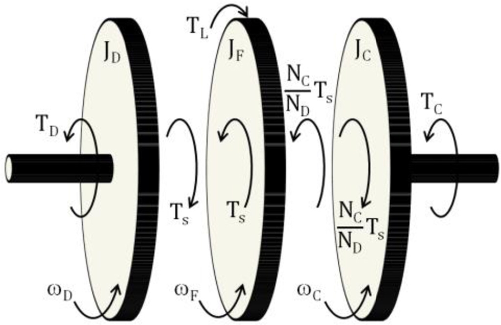
식(11)이 의미하는 것은 외측 PM의 회전에 의해 내측 PM과 HM간에 감속비가 달라져도 토크 비는 일정하다는 것이다. 즉, MG에서 토크 비는 각 구성 모듈의 극수 비에만 의존하며 이러한 관계를 고려한 3관성 MG의 토크 다이어그램은
Fig. 8과 같다. 본 장에서는 상기 가변 기어비 MG의 동특성을 모델링하고 실제 시스템을 이용한 시험 결과와 비교한다.
Fig. 8 Torque diagram of MG with variable reducing ratio, composed of three rotating rotors
3.1 이론 모델을 통한 전달함수 유도
내측 PM, HM, 외측 PM의 회전관성모멘트를 각각
JD,
JF,
JC라 하고 내측 PM과 외측 PM 구동 토크를
TD,
TC라 하면
Fig. 8에 묘사된 3관성 MG의 운동 방정식은
식(12),
(13),
(14)와 같이 나타낼 수 있다.
여기에서
TL은 부하에 해당하는 출력축 외란이고
Ts는
식(8)에 주어진 MG의 전자기 토크
TX이다. 실제
Ts는 부하각(Load Angle)에 의해 결정되는데
식(6)의 시간 적분을 고려하면
식(15)와 같이 표현할 수 있다.
선형 토크 상수
ks는 회전각에 따른 토크 시뮬레이션 선도에서 원점에서의 접선 기울기로 간주될 수 있으며 대략 35.1 Nm/rad의 값을 갖는다.
식(15)를
식(12),
(13),
(14)에 넣어 정리하면 동 시스템의 지배 방정식은
식(16)과 같은 행렬식으로 나타낼 수 있다.
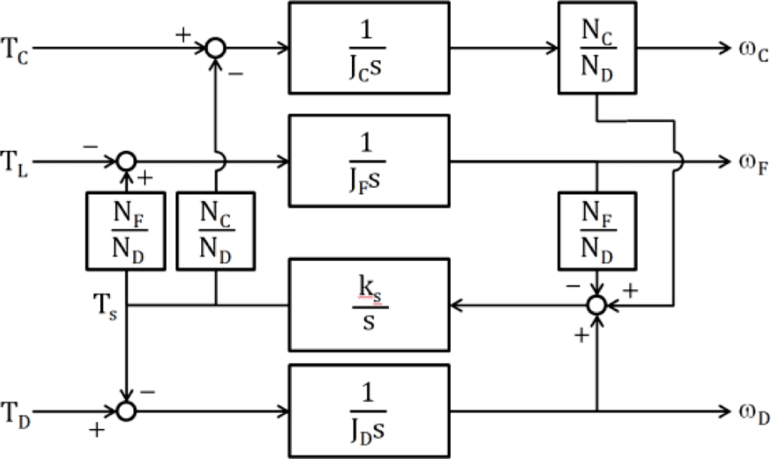
Fig. 9A block diagram of MG considering reducing ratios between each layer

유도된 지배 방정식을 기초로 각 레이어간의 감속비를 고려하여 시스템의 입출력 변수간의 관계를 블록선도로 표시하면
Fig. 9와 같다. MG를 구동시키는 입력은 외부에서 주어지는 토크
TD이고 출력은 내측 PM의 속도
ωD 혹은 HG의 속도
ωF 등이다.
ωF의 값을 조절하는 또 하나의 입력으로
TC를 들 수 있으며 외측 제어기의 속도
ωC 역시 어떤 측면에서는 또 다른 출력의 역할을 한다. 상기 방정식에서
TD와
ωD간의 전달함수를 예시하면
와 같이 유도되는데 실제 고유진동수
ωn과 반공진 진동수
ωa는
식(18),
(19)와 같이 표현된다.
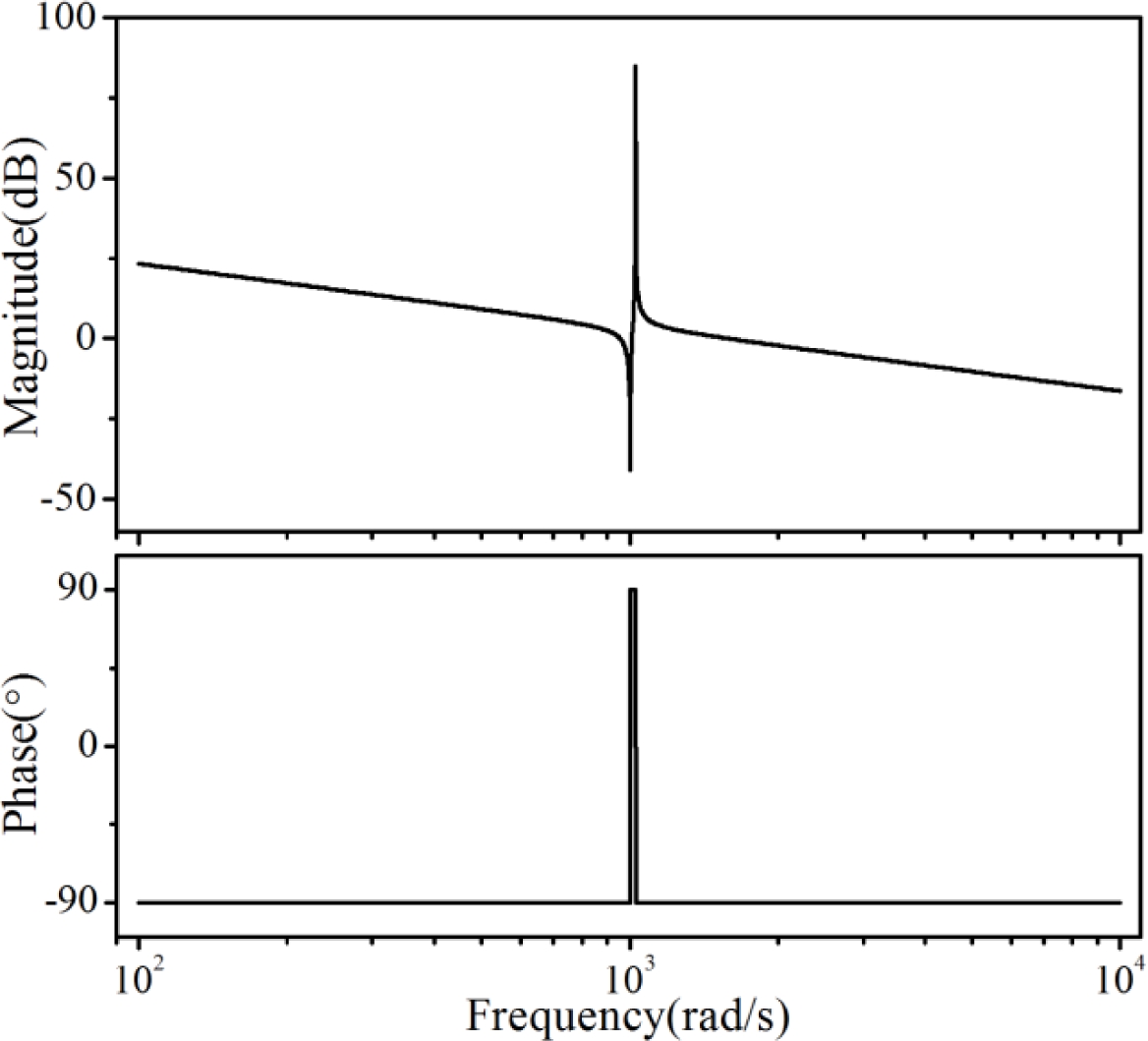
식(17)을 보데선도로 묘사하면
Fig. 10과 같은데 이 때 고유진동수는 대략 160 Hz의 값을 갖는다. 이러한 수준의 대역폭은 상대적으로 작은 공극 크기와 높은 자력 밀도에 의한 것이며 일반적인 2관성 공진계와는 달리 과다한 상승시간에 따른 시간지연 특성은 뚜렷하지 않을 것이라 예상되며 이는 실제 후술하는 응답 시험 결과를 통해서도 확인할 수 있다.
Fig. 10Bode diagram of the transfer function between the driving torque of inside PM layer and its rotation speed
3.2 실 시스템을 이용한 응답 특성과의 비교
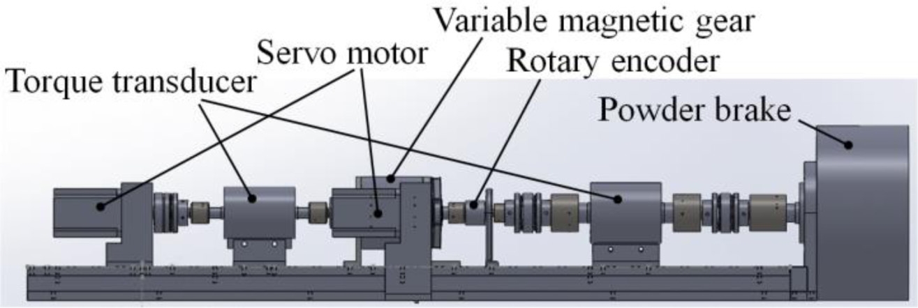
앞서 묘사한 가변 기어비 MG의 실험적 검증을 위해
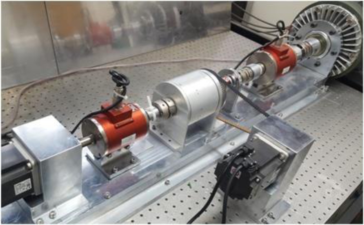
Fig. 11과 같은 테스트 모델을 구축하였다. 동 시험 장치는 MG의 응답 특성과 부하에 따른 전달 토크 측정을 위한 인하우스 동력계(In-House Dynamometer)로서 MG의 내측 PM 레이어 회전을 위한 서보모터와 외측 PM 레이어 회전을 위한 서보모터가 구동 입력 역할을 한다. 외측 레이어 회전을 위해 MG의 외측과 서보모터는 벨트, 풀리 메커니즘으로 연결되어있다. 내측 구동 토크와 HM의 출력 토크 측정을 위한 토크 센서가 중간에 놓여있고 각 단의 회전 속도 측정을 위한 엔코더가 부착되어있다. 서보 모터 입력 토크의 값은 내장된 자체 루프에 의해 궤환되어 측정 가능하다. 또한 출력축 부하 인가는 우측단의 파우더 브레이크로 구현되는데 실제 MG의 제원은
Table 1에 제시된 모의시험에 이용된 제원과 동일하다.
Fig. 11Photograph of the magnetic gear prototype for verifying a variable reducing ratio

Fig. 12Hardware implementation of the in-house dynamometer describing each component of Fig. 11
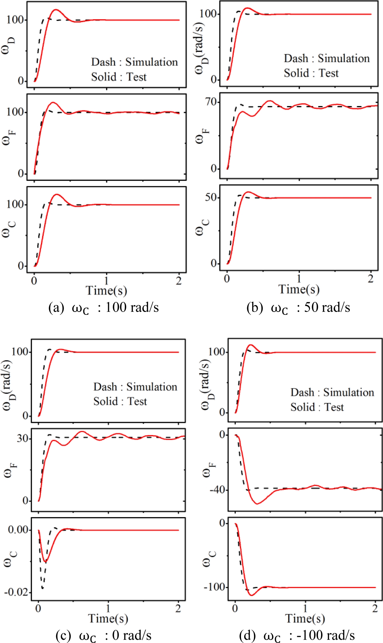
시험 장치를 이용한 시험 내용은 MG의 기어비 가변에 따른 응답 특성과 토크 크기의 변화 특성이다. 우선, MG의 외측 PM레이어의 속도
ωC를 변화시킬 때 출력축인 HM의 속도
ωF의 응답 특성이다. 정량적 비교를 위해 모든 시험에서 내측 PM 레이어의 속도
ωD는 100 rad/s로 설정하였다. 유의해야 할 점은
ωD와
ωC는 서보 모터 축의 속도에 해당하므로 진정한 의미의 출력 속도는
ωF이다.
ωC가 각각 100, 50, 0, -100 rad/s일 때
ωF의 응답 선도를
Fig. 13에 나타내었다.
식(7)을 통해 설정된
ωD와
ωC가 주어질 때
ωF의 값을 이론적으로 계산해보면 100, 65.4, 30.77, -38.46 rad/s이다.
Fig. 13의 각 그림에서 상기 수치에 정확하게 일치하는
ωF의 값을 확인할 수 있는데 이는 MG가 동기 모터와 동일하게 각 레이어가 극 정렬 방식에 의해 동기되어 움직이기 때문이다. 그림에서
ωD와
ωC는
식(16)의 지배 방정식을 기초로 하는 PI 제어기에 의한 응답 결과이며 모의시험보다는 실험 결과에서 좀 더 긴 상승시간을 확인할 수 있다. 특히
ωF의 실험 결과에서는 잔류 진동의 발생을 확인할 수 있으며 이는 공진계 특성에 기인하는 것으로 판단된다. 해당 실험은 무부하 시험이며 부하가 커짐에 따라 이러한 잔류 진동의 크기는 감소한다.
Fig. 13Response of the harmonic modulator according to a speed change of outer PM layer, under a constant inner PM layer speed

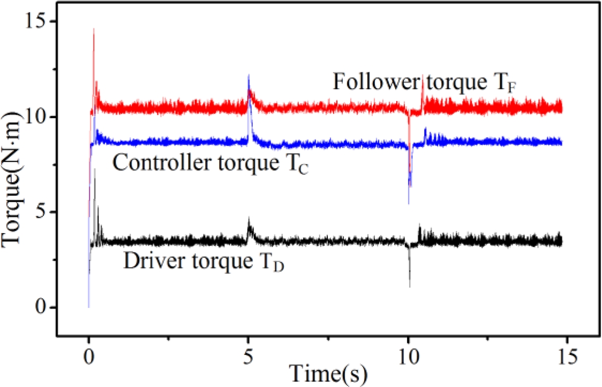
다음으로
ωC가 100 rad/s에서 5초 후에 50 rad/s로 감소했다가 다시 5초 후에 100 rad/s으로 복원되었을 때 각각의 회전체에 발생하는 토크를 측정하여
Fig. 14에 제시하였다. 해당 결과는 출력축인 HM에 10 N × m의 부하를 인가한 상태에서
ωC의 속도를 가변시켜가며 측정한 결과이며
ωD는 모두 100 rad/s로 동일하다.
Fig. 13에서
ωC가 100 rad/s일 때 와 50 rad/s일 때
ωD와
ωF의 감속 비는 각각 1/1, 1/0.65이지만 본 장의 서두에 기술한 바와 같이 토크 비는 속도 변화에 상관없이 모두 모듈의 극수 비와 동일하게 대략 4:13:9의 비를 갖는 것을 확인할 수 있다. 물론 5초, 10초에서 갑작스런 속도 변화로 약간의 오버슈트 현상 역시 확인할 수 있다. 각각의 토크 값은 해당 모듈의 관성부하를 포함하기 때문에 외란으로 작용하는 HM의 부하 10 N × m를 기준으로 계산되는 3.2 N × m, 7.2 N × m 보다는 약간 크지만 극수 비와 거의 유사한 토크 값을 나타낸다. 이는 외측 모듈의 회전에 따른 감속비의 변화와 관계없이 해당 토폴러지에서 토크 비는 초기 설계 극수 비에 의해 결정된다는 것을 의미한다.
Fig. 14Torque response of each module according to ωC under 10 N × m load assigned to the harmonic modulator

4. 결론
원주 방향에 놓인 모든 PM이 토크 발생에 기여하는 MG는 기계식 기어의 토크 전달 밀도에 필적하는 토크 생성이 가능하여 그 응용이 활발히 모색되고 있다. 특히, 과부하에서 전달 시스템의 기계적 항복이나 파손 등의 가능성이 상대적으로 작으므로 유지보수 측면에서 사용자의 관여를 최소화할 수 이점이 있고 따라서 지속적인 모니터링이 어려운 환경에 폭넓게 활용될 수 있다. 현재 적용이 추진되고 있는 분야로 연근해 연안의 풍력발전이나 원전 등이 있으며 이외 비접촉으로 인한 마찰 손실 저감에 따른 효율 증가 이득을 얻을 수 있는 전기자동차용 파워 트레인 등을 목표로 한 연구가 활발히 진행되고 있다. 이러한 MG는 일반적으로 각 구성 모듈의 극수에 의해 결정되는 고정 감속비를 갖는 것으로 알려져 왔으나 특정 모듈을 고정시키지 않고 변속을 시키면 감속비를 폭넓게 구현할 수 있는 장점이 있다. 본 연구에서는 이처럼 감속비를 가변시킬 수 있는 MG를 대상으로 자기 퍼미언스를 활용한 이론적인 방법과 실험적 검증을 통해 해당 토폴러지의 타당성을 분석하였다. 특히 기존 연구와는 달리 모듈간의 감속비를 모두 고려하여 동특성을 분석하고 입출력간의 주파수 응답 특성을 제시하였다. 본 논문의 주요 결과는 다음과 같이 요약할 수 있다.
첫째, MG의 감속비는 MG를 구성하는 모든 모듈의 회전 속도에 따라 결정되며 특정 모듈의 속도를 제어하면 이러한 감속비를 연속적으로 가변시킬 수 있다.
둘째, MG의 토크비는 MG를 구성하는 각 모듈의 극수비에 의해 결정되며 감속비와는 무관하게 결정된다.
셋째, 가변 기어비 MG는 3관성 시스템임에도 2관성 공진계와 동일한 주파수 응답 특성을 갖는다.
ACKNOWLEDGMENTS
본 연구는 중소벤처기업부의 중소기업융복합기술개발사업(S2449707, 마그네틱 기어 일체형 0.75 kW급 지능형 휠 구동시스템 개발)과 정부(교육부)의 재원으로 한국연구재단의 기초연구사업(NRF-2016R1D1A1B03930283) 지원에 의한 연구임.
REFERENCES
- 1.
Rasmussen, P. O., Andersen, T. O., Jorgensen, F. T., and Nielsen, O., “Development of a High-Performance Magnetic Gear,” IEEE Transactions on Industry Applications, Vol. 41, No. 3, pp. 764-770, 2005.
10.1109/TIA.2005.847319
- 2.
Kim, M. S. and Jung, K. S., “Magnet Gear with Two-Axial Magnetic Paths,” Journal of the Korean Society for Precision Engineering, Vol. 31, No. 6, pp. 543-550, 2014.
10.7736/KSPE.2014.31.6.543
- 3.
Aho, J. and Kraft, L. G., “Control of a Wind Turbine with a Magnetic Continuously Variable Transmission for Mitigation of Torque Variations,” Proc. of the American Institute of Aeronautics and Astronautics Aerospace Sciences 49th Conference, pp. 1-28, 2011.
10.2514/6.2011-816
- 4.
Oh, Y.-J., Ha, K.-H., and Hong, J.-P., “Characteristic Analysis of Touch Free Gear Using Permamant Magnet,” Proc. of the Korean Institute of Electrical Engineers Conference, pp.18-20, 2001.
- 5.
Jian, L. and Chau, K.-T., “Design and Analysis of a Magnetic-Geared Electronic-Continuously Variable Transmission System using Finite Element Method,” Progress In Electromagnetics Research, Vol. 107, pp. 47-61, 2010.
10.2528/PIER10062806
- 6.
Atallah, K., Wang, J., Calverley, S. D., and Duggan, S., “Design and Operation of a Magnetic Continuously Variable Transmission,” IEEE Transactions on Industry Applications, Vol. 48, No. 4, pp. 1288-1295, 2012.
- 7.
Atallah, K., Calverley, S., and Howe, D., “Design, Analysis and Realisation of a High-Performance Magnetic Gear,” Proc. of the Electric Power Applications Conference, Vol. 151, No. 2, pp. 135-143, 2004.
10.1049/ip-epa:20040224
- 8.
Toba, A. and Lipo, T. A., “Generic Torque-Maximizing Design Methodology of Surface Permanent-Magnet Vernier Machine,” IEEE Transactions on Industry Applications, Vol. 36, No. 6, pp. 1539-1546, 2000.
10.1109/28.887204
- 9.
Wang, J., Atallah, K., and Carvley, S., “A Magnetic Continuously Variable Transmission Device,” IEEE Transactions on Magnetics, Vol. 47, No. 10, pp. 2815-2818, 2011.
10.1109/TMAG.2011.2157470
Biography
- Hoon Hee Won
M.Sc. candidate in the Department of Mechanical Engineering, Korea National University of Transportation. His research interest is magnetic gear-embedded motor.
- Kwang Suk Jung
Professor in the Department of Mechanical Engineering, Korea National University of Transportation. His research interests include electromagnetic energy conversion device, magnetic gear, power transmission of electric vehicle, and magnetic levitation application.