ABSTRACT
A new technique based on the reversal method, is suggested to measure squareness error of the two-linear axes system. The technique uses the L-type steel bar, a capacitive sensor, and three experimental installations required to measure squareness error and two horizontal straightness errors. Profile and squareness of the L-type steel bar are estimated, by using the principle of the reversal method. Also, setup errors inevitable at installation, are separated from measured data using the least square method. Multi-DOF errors of two-linear axes system are measured and analyzed, using the suggested technique. Also, the reference mirror with flatness of 30 nm is used to verify the suggested measurement technique. Difference between the two measurement methods is 3.25 arcsec, a value within measurement repeatability.
-
KEYWORDS: Positioning accuracy, Geometric error, Squareness error, Reversal method
-
KEYWORDS: 위치 정확도, 기하학적 오차, 직각도 오차, 반전법
1. 서론
정보통신기기, 우주항공 및 첨단 자동차 등의 차세대 주력 산업을 위해 고신뢰성 기계 부품 활용이 증가됨에 따라 정밀 제조산업에서 광범위하게 사용하고 있는 다축 직선 이송계의 위치 정확도 개선의 필요성이 증대되고 있다.
1,2 다축 직선 이송계에 영향을 끼치는 주요 오차들 중 하나인 기하학적 오차는 일반적으로 PDGEs (Position Dependent Geometric Errors)와 PIGEs (Position Independent Geometric Errors)로 구분한다.
3,4 PDGEs는 이송계 요소 부품의 불완전한 형상에 의해 야기된 오차이며 단일 직선 이송계의 3자유도 위치 오차와 3자유도 각도 오차로써 정의한다. 또한 PIGEs는 직선 이송계간의 조립 오차로써 직각도 오차를 나타낸다. 다축 직선 이송계에서 직각도 오차는 기하학적 오차 중에 상당히 큰 비중을 차지하기 때문에 정확한 측정 기법이 필요하다.
5,6
직각도 오차를 측정하기 위해 상용 측정 장비를 이용하여 현장에서 활용하고 있으며, 이러한 장비를 기반으로 다양한 측정 방법이 제안, 개발되었다.
7-15 레이저 간섭계는 정밀 측정 장비로써 직선, 회전축, 다축의 기하학적 오차 측정에 활용된다. 그러나 직각도 오차를 측정하기 위해서는 고 측정 기술 및 비용이 요구된다.
11
반면, 볼바 시스템은 다축 직선 이송계의 성능진단과 직각도 오차 추정에 적합하다.
12,13 그러나 제한된 원호 구간내의 오차 추정만 가능하며, 상대적으로 타 장비에 비해 성능이 낮아 정확한 추정이 어렵다. 따라서, 정확한 측정을 위해 정전용량 센서와 기준 미러를 이용한 방법이 활용된다. Lee는 최적 5자유도 측정 시스템을 개발하여 2축 직선 이송계의 오차를 측정하는 방법을 제안하였다.
14,15 그러나 기준 미러의 측정 영역 이내에서는 나노급의 정확한 오차 측정이 가능한 반면, 전체 이송 영역을 추정하기 위해서는 고가의 측정 미러가 요구된다. 이러한 단점을 보완하기 위해 반전법이 개발되었으나, 이 방법은 단일 축의 기하학적 오차 측정에 제한적이다.
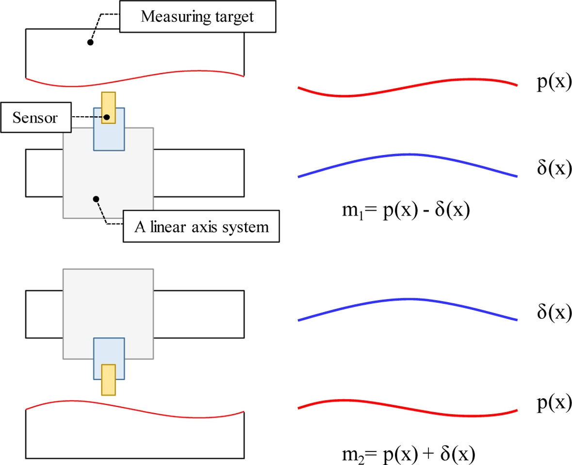
Fig. 1 Reversal method schematic for the straightness error measurement

본 연구에서는 반전법 기반의 새로운 측정 기법을 제안하여 2축 직선 이송계의 다자유도 오차를 측정한다. L 구조의 측정 타겟(Measuring Target)과 정전용량 센서를 이용하여 수평 진직도 오차와 직각도 오차를 추정한다. 2장에서는 제안한 측정 기법을 활용한 다자유도 오차 측정 방법과 수학적 검증을 설명한다. 3장에서는 제안한 방법의 타당성을 검증하기 위해 2축 직선 이송계의 다자유도 오차를 측정하고 분석한 결과를 기술한다. 마지막으로 4장에서는 본 연구를 정리 및 요약하여 결론을 나타내고 활용방안을 제시한다.
2. 반전법 기반의 다자유도 오차 측정 기법
2.1 반전법의 측정 원리
반전법은 단일 직선 이송계의 진직도 오차 측정을 위해 주로 활용된다. 2회 측정 실험이 요구되며, 센서 측정값을 이용하여 측정 타켓의 형상
p(
x)과 진직도 오차
δ(
x)를 추정한다. 각각의 실험에 측정된 센서 값은
식(1)과 같고 연립 방정식을 이용하여 진직도 오차와 측정 타겟의 형상을 계산한다.
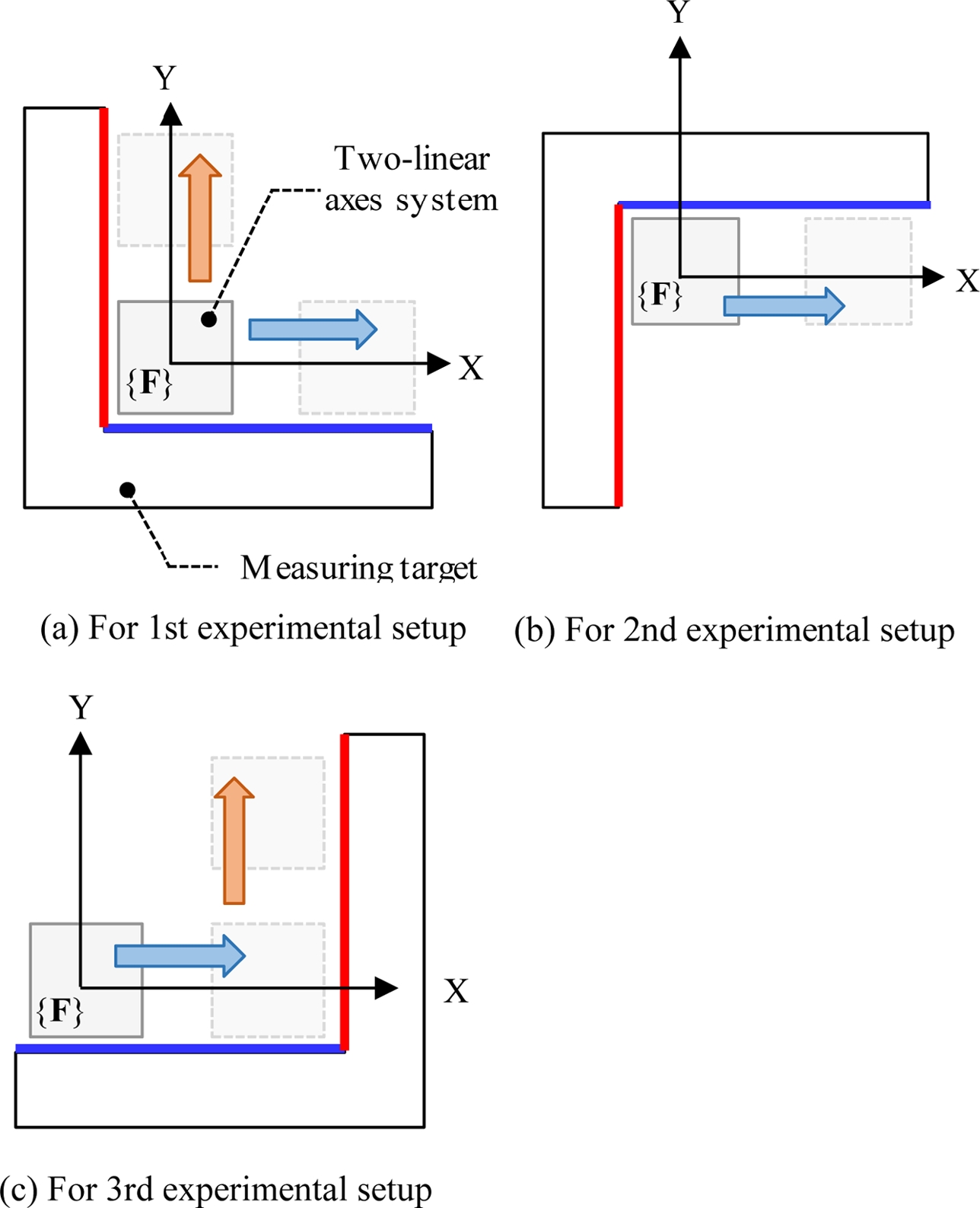
2축 직선 이송계의 수평 진직도 위치 오차와 직각도 오차 측정을 위해 반전법 기반의 측정 기법을 제안한다. L구조의 측정 타겟과 정전 용량 센서를 이용하며,
Fig. 2와 같이 3회 셋업이 요구된다. 측정된 5개의 센서 값을 이용하여 수평 진직도
δxy,
δyx와 직각도 오차
szy를 추정한다.
Fig. 2Measurement sequence

3회 실험에서 측정값은 측정 타겟의 셋업 오차
θi (
i = 1, 2, 3)에 의해 일정한 기울기를 나타낸다. 각 실험에서의 측정값은
mij (
i = 1, 2, 3,
j =
x,
y)로 표기하며,
i는 실험 순번을 나타내고,
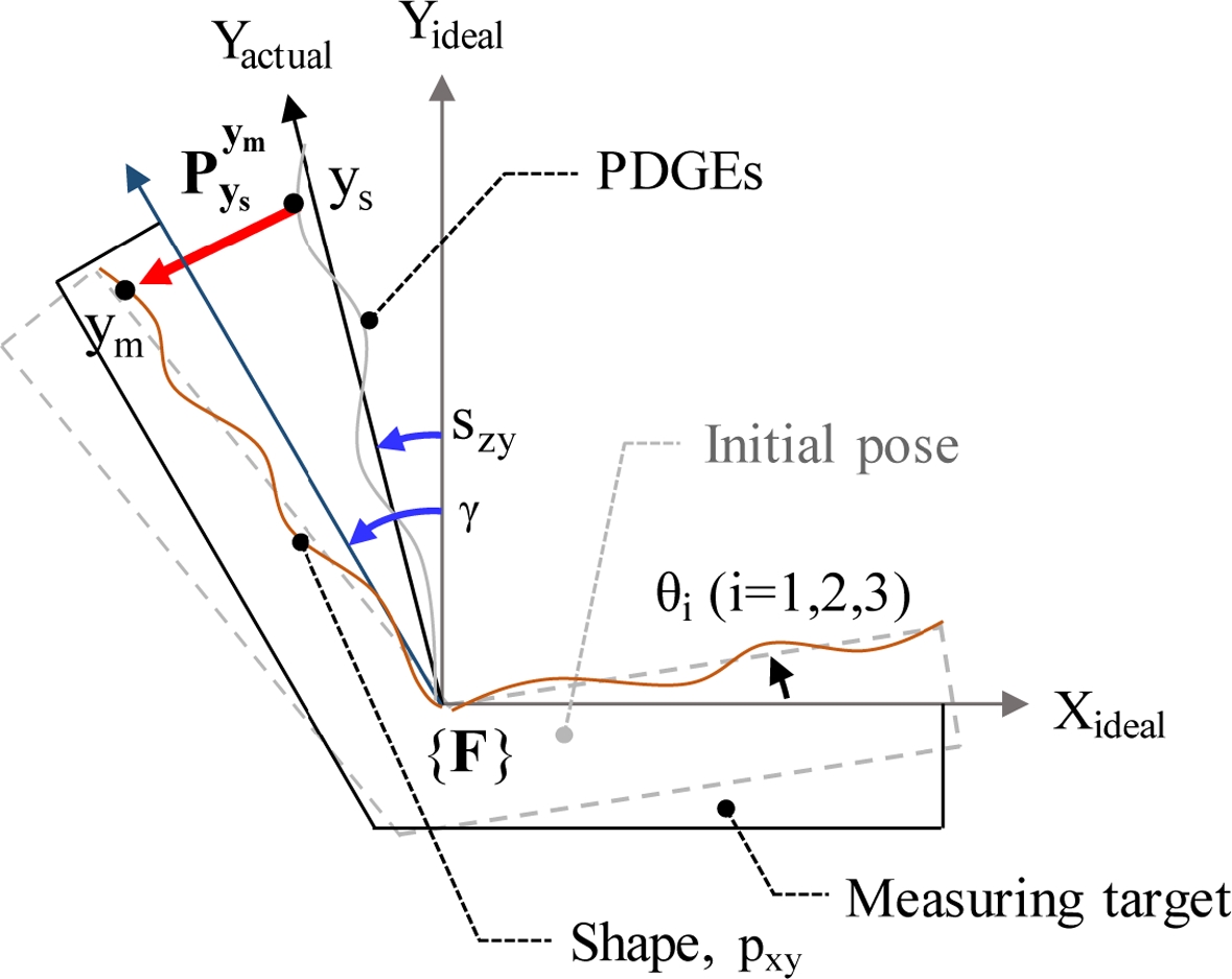
j는 측정 이송 방향을 의미한다. 여기서, 직각도
γ는 L구조의 측정 타겟 조립 오차에 의해 불가피하게 발생하며
Fig. 3과 같다. 직선 이송계간의 직각도 오차는
szy로 표기하며, 각 직선 이송계의 수평 진직도 오차와 측정 타겟의 형상은 각각
δij와
pij로 표기하며,
i는 오차 방향을 나타내고
j는 측정 이송 방향을 의미한다.
xs,
xm,
ys,
ym는 각각 x, y축 방향의 센서의 위치와 타겟의 측정 위치를 의미한다.
Fig. 3Analysis of measured data in an experimental setup
정확한 오차 측정을 위해서는 센서값에 영향을 끼치는 셋업 오차
θi (
i = 1, 2, 3)의 영향을 최소화해야 한다. 실험에서는 L형 치구를 이용하기 때문에 각 셋업에서의 측정값은 동일한 셋업 오차의 영향을 받는다. 따라서, 기준 좌표계 {
F}에서 오차를 정의하기 위해 최소 자승법(Least Square Method)을 활용하여 셋업 오차를 추정하고 제거한다. 1차 셋업에서의 직선 이송계의 위치에 따른 센서와 측정 타겟 위치 간의 백터는
식(2)와 같다. 센서의 방향에 의해 측정 민감도는 동일한 방향으로 큰 비중을 차지하며, 센서 측정값은
식(3)과 같다. 이때, 셋업 오차
θ1의 영향을 제거한 측정값을
식(4)와 같이 재정리한다.
Where,
동일한 방법을 이용하여 2, 3번째 실험 결과에서 측정된 센서의 값을 계산하며
식(5)와 같다. 이 때, 3차 셋업에서 x 축 방향의 측정값은 역방향 형상을 포함하기 때문에 1 - 2차 셋업에서 추정된 형상 정보를 토대로
p'yx를 계산한다.
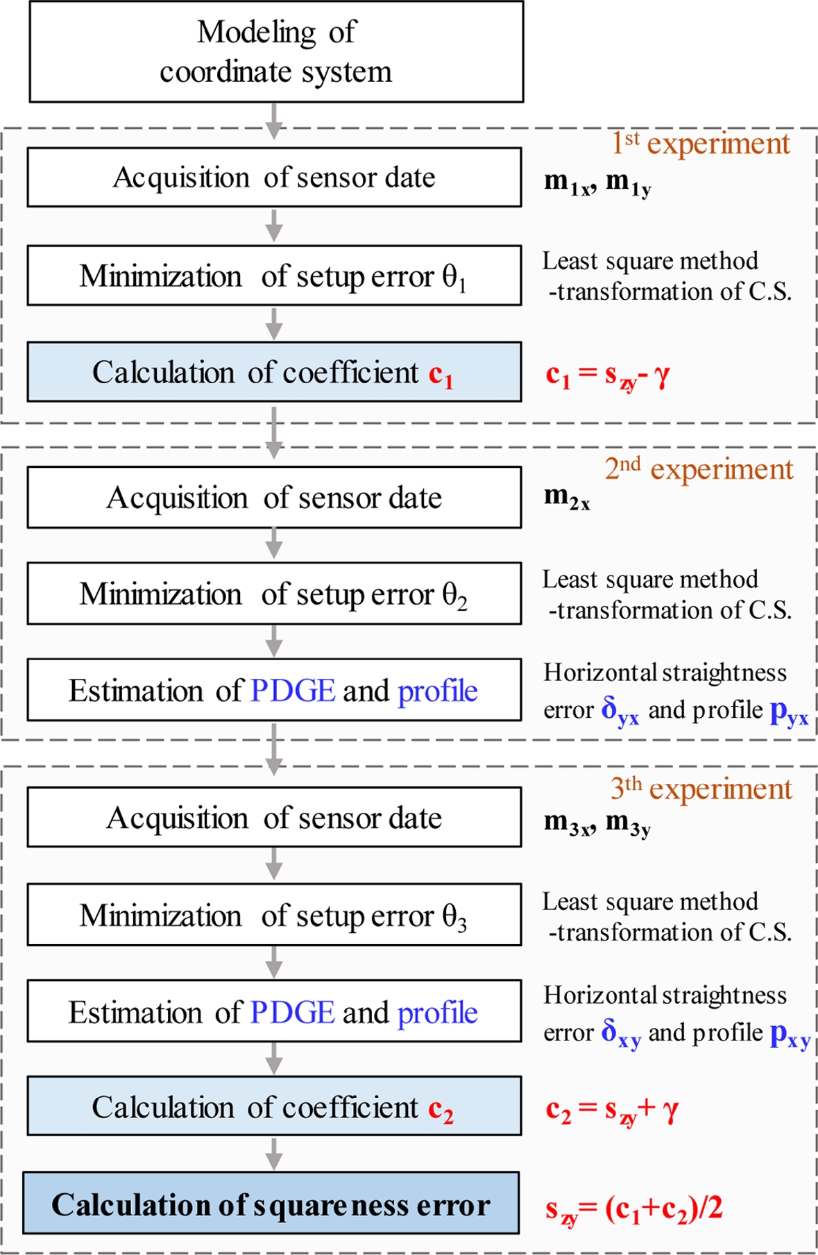
식(3),
(5)와 같이 1, 3차 셋업에서 측정된 결과
m1x,
m1y,
m3y로부터 최소 자승법을 이용하여 계수
c1,
c2를 추정한다. 이때 추정된 계수는 측정 타켓의 직각도
γ와 직선 이송계간의 직각도 오차
szy로 구성되며
식(6)과 같다. 추정된 계수를 이용하여 직각도 오차
szy를 계산하며, 2축 직선 이송계의 직각도 오차 추정을 위한 알고리듬 순서도는
Fig. 4와 같다.
Fig. 4The procedure of suggested measurement technique
3. 다자유도 오차 측정 실험 및 타당성 검증
제안한 오차 측정 알고리듬을 이용하여 2축 직선 이송계의 수평 진직도
δyx,
δxy와 직각도 오차
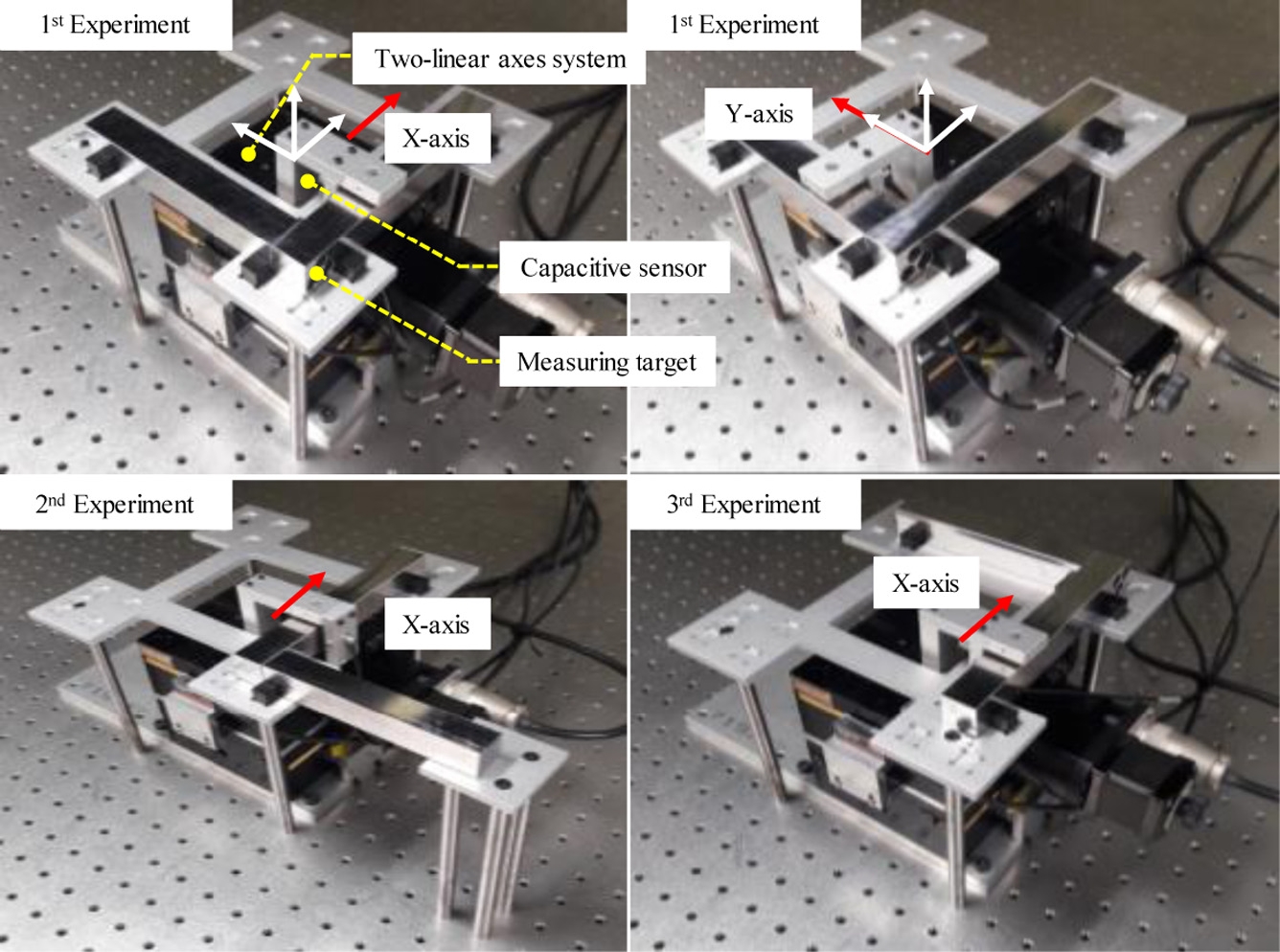
szy를 측정한다. 실험에는 정전용량 센서(4810 Module, 2805 Probe, A 4810, Probe, ADE Technology inc., U.S.A.)와 L구조의 측정 타겟을 이용하였으며
Fig. 5와 같이 실험 장비를 설치한다. 측정 타겟은 추가로 설계된 치구에 고정되며, 정전용량 센서는 스테이지의 테이블에 설치되어 이송에 따른 측정값을 획득한다. 3회 실험 셋업에서 센서의 측정값
mij은
Fig. 6과 같으며 셋업 오차
θi (
i = 1, 2, 3)에 의해 측정값
mij은 증가 또는 감소된 경향을 보인다. 따라서, 최소 자승법을 이용하여 기준 축인 X축의 측정값
mix (
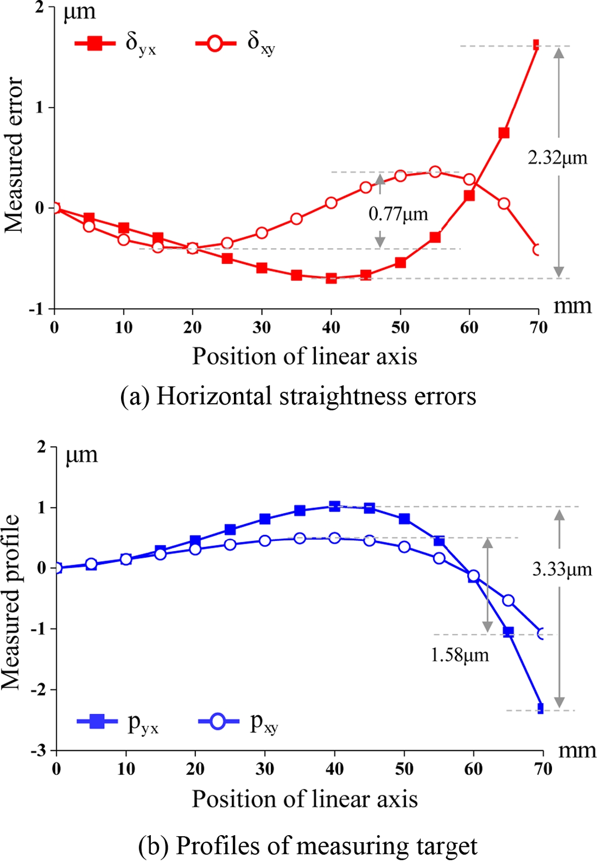
i = 1, 2, 3)의 셋업 오차를 추정하고 좌표 변환함으로써, 측정된 결과에서의 셋업 오차 영향을 최소화한다. 제안한 알고리듬을 기반으로 측정된 결과로부터 다자유도 오차를 측정한다. 각 이송계의 수평 진직도 오차
δyx,
δxy와 측정 타겟의 형상
pyx,
pxy은
Fig. 7과 같이 계산되며, 측정된 수평 진직도와 타겟 형상의 PV는 각각 2.32 μm, 0.77 μm이다. 또한 계산된
c1,
c2를 이용하여 측정된 조립 오차와 직각도 오차는 각각 -185 Arcsec, 108 Arcsec이다.
Fig. 5 Experimental setup for multi-DOF error measurement

Fig. 6 Measured raw data and setup error estimation
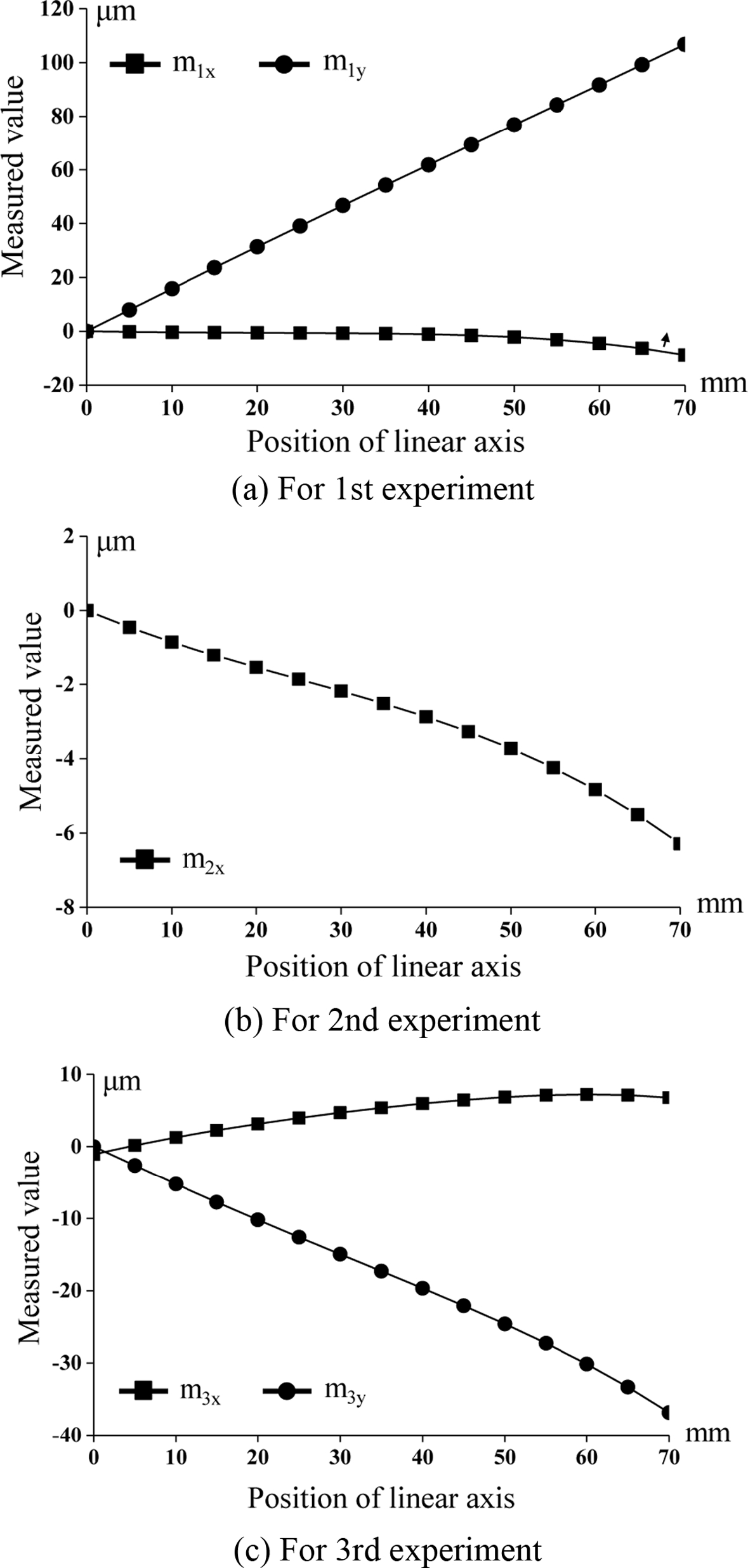
Fig. 7 Estimation of multi-DOF errors using suggested measurement technique
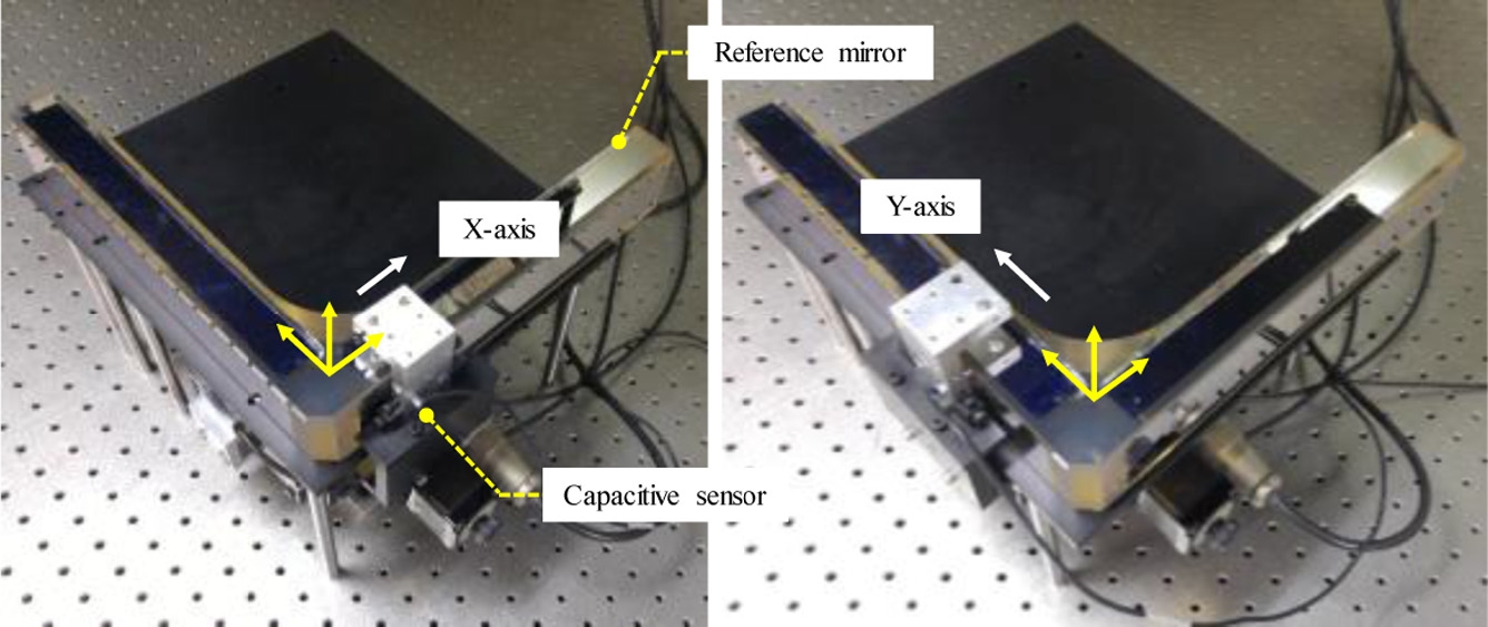
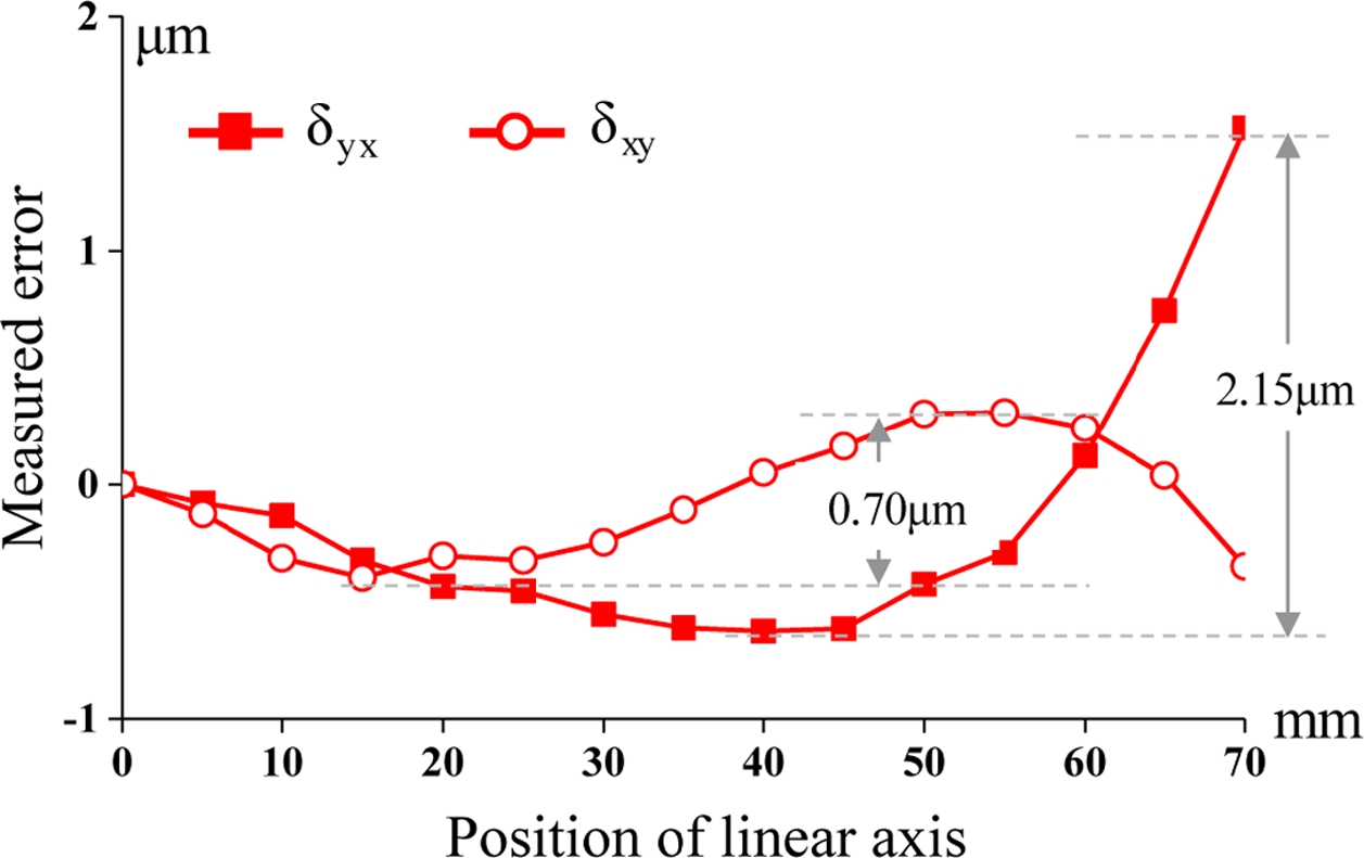
측정 알고리듬의 타당성을 검증하기 위해 L 구조의 기준 미러(L-mirror, LITTO Optical Co., ltd. Japan)와 정전용량 센서를 이용하여 2축 직선 이송계의 진직도 오차를 측정한다.
Fig. 8과 같이 실험에 사용된 기준 미러의 평탄도는 ±30 nm이고 측정면 간의 직각도는 1 Arcsec이다. 두 측정 방법에 의한 실험 결과는
Table 1과 같이 정리하였으며 5회 반복하여 측정된 평균값을 토대로 측정된 오차의 PV (Peak to Valley) 값과 RMSE (Root Mean Square Error) 값을 계산하고 비교한다. 실험 결과에서 측정된 진직도 오차 간의 최대 차이는 170 nm이다. 또한 직각도 오차는 3.25 Arcsec의 차이를 가지며, 이 값은 반복 정밀도 이내의 값을 가지므로 제안한 2축 직선 이송계의 다자유도 오차 측정 기법의 타당성을 검증하였다.
Fig. 8 Experimental setup using L-type reference mirror

Fig. 9 Measured straightness errors using L-type reference mirror

Table 1 Summarization of experimental results
Table 1
|
Unit: μm, arcsec |
Suggested technique |
Reference mirror |
Difference |
|
δyx
|
PV |
2.32 |
2.15 |
0.17 |
|
RMSE |
0.62 |
0.59 |
0.03 |
|
δxy
|
PV |
0.77 |
0.70 |
0.07 |
|
RMSE |
0.28 |
0.25 |
0.03 |
|
szy
|
|
108 |
102 |
3.25 |
5. 결론
본 연구에서는 본 연구에서는 2축 직선 이송계의 다자유도 오차 측정을 위해 반전법 기반의 측정 기법을 제안한다. 단일 정전 용량 센서와 L 구조의 측정 타겟을 이용하고, 3회의 측정 실험으로부터 수평 진직도 오차와 직각도 오차를 측정한다. 또한 정확한 오차 측정을 위해 측정 타켓의 형상, 조립 및 셋업 오차를 추정한다. 소형 2축 직선 이송계를 대상으로 제안한 방법을 활용하여 2개의 수평 진직도 오차와 직각도 오차를 측정한다. 또한 제안한 측정 기법의 타당성을 검증하기 위해 초정밀 L-형 구조의 기준 미러를 활용한다. 두 측정 방법의 최대 차이는 3.25 Arcsec이며 측정 반복정밀도 이내의 값을 가진다. 본 연구에서 제안한 기법을 활용하여 임의의 구조를 가진 다축 직선 이송계의 직각도 오차 측정이 가능하다. 따라서, 다축 직선 이송계의 주요 오차인 직각도 오차를 측정하고 보정함으로써 위치 정확도 개선에 기여할 것으로 기대된다.
ACKNOWLEDGMENTS
이 논문은 2016년도 정부(교육부, 미래창조과학부)의 재원으로 한국연구재단의 중견연구사업(2017R1A2B2009475)과 이공학개인기초과제(2017R1D1A3B03030083)로 수행된 연구임.
REFERENCES
- 1.
Lee, K.-I. and Yang, S.-H., “Accuracy Evaluation of Machine Tools by Modeling Spherical Deviation Based on Double Ball-Bar Measurements,” International Journal of Machine Tools and Manufacture, Vol. 75, pp. 46-54, 2013.
10.1016/j.ijmachtools.2013.09.001
- 2.
Slocum, A., “Kinematic Couplings: A Review of Design Principles and Applications,” International Journal of Machine Tools and Manufacture, Vol. 50, No. 4, pp. 310-327, 2010.
10.1016/j.ijmachtools.2009.10.006
- 3.
Lee, J.-C., Lee, K.-I., and Yang, S.-H., “Development of Compact Three-Degrees-of-Freedom Compensation System for Geometric Errors of an Ultra-Precision Linear Axis,” Mechanism and Machine Theory, Vol. 99, pp. 72-82, 2016.
10.1016/j.mechmachtheory.2015.12.015
- 4.
ISO 230-1:2012, “Test Code for Machine Tools - Part 1: Geometric Accuracy of Machines Operating Under No-Load or Quasi-Static Conditions,” 2012.
- 5.
Kreng, V., Liu, C., and Chu, C., “A Kinematic Model for Machine Tool Accuracy Characterisation,” The International Journal of Advanced Manufacturing Technology, Vol. 9, No. 2, pp. 79-86, 1994.
10.1007/BF01750414
- 6.
Lee, J. H., Liu, Y., and Yang, S.-H., “Accuracy Improvement of Miniaturized Machine Tool: Geometric Error Modeling and Compensation,” International Journal of Machine Tools and Manufacture, Vol. 46, Nos. 12-13, pp. 1508-1516, 2006.
10.1016/j.ijmachtools.2005.09.004
- 7.
Lee, D.-M., Zhu, Z., Lee, K.-I., and Yang, S.-H., “Identification and Measurement of Geometric Errors for a Five-Axis Machine Tool with a Tilting Head Using a Double Ball-Bar,” International Journal of Precision Engineering and Manufacturing, Vol. 12, No. 2, pp. 337-343, 2011.
10.1007/s12541-011-0044-5
- 8.
Castro, H. and Burdekin, M., “Dynamic Calibration of the Positioning Accuracy of Machine Tools and Coordinate Measuring Machines Using a Laser Interferometer,” International Journal of Machine Tools and Manufacture, Vol. 43, No. 9, pp. 947-954, 2003.
10.1016/S0890-6955(03)00083-X
- 9.
Lai, T., Peng, X., Tie, G., Liu, J., and Guo, M., “High Accurate Squareness Measurement Squareness Method for Ultra-Precision Machine Based on Error Separation,” Precision Engineering, Vol. 49, No. pp. 15-23, 2017.
10.1016/j.precisioneng.2017.01.005
- 10.
Aguado, S., Samper, D., Santolaria, J., and Aguilar, J. J., “Identification Strategy of Error Parameter in Volumetric Error Compensation of Machine Tool Based on Laser Tracker Measurements,” International Journal of Machine Tools and Manufacture, Vol. 53, No. 1, pp. 160-169, 2012.
10.1016/j.ijmachtools.2011.11.004
- 11.
Lee, H. H., Lee, D. M., and Yang, S. H., “Squareness Estimation for Coordinate Measuring Machine Using the Laser Interferometer Measurement Based on the Face-Diagonal Method,” Journal of the Korean Society for Precision Engineering, Vol. 33, No. 4, pp. 295-301, 2016.
10.7736/KSPE.2016.33.4.295
- 12.
Lee, H.-H., Lee, D.-M., and Yang, S.-H., “A Technique for Accuracy Improvement of Squareness Estimation using a Double Ball-Bar,” Measurement Science and Technology, Vol. 25, No. 9, Paper No. 094009, 2014.
10.1088/0957-0233/25/9/094009
- 13.
ISO 230-4:2005, “Test Code for Machine Tools - Part 4: Circular Tests for Numerically Controlled Machine Tools,” 2005.
- 14.
Lee, J.-C., Lee, H.-H., and Yang, S.-H., “Total Measurement of Geometric Errors of a Three-Axis Machine Tool by Developing a Hybrid Technique,” International Journal of Precision Engineering and Manufacturing, Vol. 17, No. 4, pp. 427-432, 2016.
10.1007/s12541-016-0053-5
- 15.
Lee, K.-I., Lee, J.-C., and Yang, S.-H., “The Optimal Design of a Measurement System to Measure the Geometric Errors of Linear Axes,” The International Journal of Advanced Manufacturing Technology, Vol. 66, Nos. 1-4, pp. 141-149, 2013.
10.1007/s00170-012-4312-z
Biography
- Jae-Chang Lee
Professor in the Division of Mechanical Engineering Technology, Yeungnam University College. His research interest is machine tools and mechatronics.
- Eun-Young Ko
MS Candidate in the Department of Mechanical Engineering, Korea Uni-versity. Her research interest is machine design.
- Kwang-Il Lee
Professor in the School of Mechanical and Automotive Engineering, Kyungil University. His research interest is CAD/CAM, machine tools and 3D printing.
- Seung-Han Yang
Professor in the School of Mechanical Engineering, Kyungpook National Uni-versity. His research interest is intelligent manufacturing systems and CAD/CAM.
Citations
Citations to this article as recorded by