ABSTRACT
Failure of conventional snowplows is usually caused by the strain put it its rotational parts. In the case of the vertical rotation, when the snowplow is rising or falling, the sensor automatically stops the rotation and the wire could be break due to the impact from an endless drive in the reverse direction or conversely from the winding of the wire. While in motion, snowplows are frequently over turned due to their heavy weight. Snowplows are manufactured with conventional steel plates and have heavy hydraulic cylinders which makes them heavy. This can result in the damaging of the vehicle due to the mounted snowplow and its malfunctions. In this study, a composite resin blade with a high-strength and is lightweight was developed for a snowplow. In order to ensure durability of the snowplows, a new bobbin was designed to mimic the clutch of a vehicle. This study was developed to eliminate the tension and fatigue of the wire by winding the chain instead of the wire in the newly designed bobbin.
-
KEYWORDS: Automated snowplow, Sprocket, Chain, Clutch bobbin, Rotating gear shaft
-
KEYWORDS: 전동 제설기, 스프라켓, 체인, 클러치 보빈, 회전 기어 샤프트
1. Introduction
The conventional snowplow driving method is mainly through an electric transmission scheme through a steel wire. In the case of this method, when the vehicle equipped with a snowplow is driving, durability problems become an issue due to the breaking of the snowplow from collision with obstacles (barrier ice). Operating expense savings can be achieved if the maintenance costs are lowered through solving this kind of issue. In addition, in order to increase the efficiency of snow removal, after mounting it to the vehicle, the development of an automatic snowplow is needed that has a remote control system which can steer from the driver’s seat by controlling the vertical and horizontal rotation free based on sensor control. The failure of the conventional snowplow frequently occurs by accumulating strain in the rotational parts of the left-right rotation. In the case of up-down rotation, when the snowplow is rising or falling to either the upper or lower direction, the wire can frequently be broken due to the infinite impact in the reverse direction rotation of the wire because the snowplow is operated automatically by sensor control when stopping. Additionally, there is the problem that the vehicle is often damaged due to the overturned snowplow because the snow blade of conventional snow plows are made of steel sheets and heavy cylinders.
1-12
In the present study, an automatic electric snowplow has been developed in which the height and angle controls are possible from a controllable sensor without using a hand-operated switch mechanism and steel wire. Instead of a wire, a sprocket and chains were applied to the snowplow for increased durability. An anti-shock device clutch connected to the motor was developed in order to ensure durability by protecting the snow blade when there is an unpredicted shock and by keeping the blade in close contact with the road. The newly designed bobbin acts like as an automotive clutch that serves to transmit the power or blocks when there is an abnormal shock from the snow blade. From these results, it is proposed that this new technology extends the life of the snowplow and does not produce an impact on the vehicle.
2. Prototype Snowplow Manufactured by Using Clutch Bobbin
Technology developed in this study aims to develop a snowplow with excellent durability to enable simultaneous snowplowing in the narrow streets of provincial or rural areas. For this, the development of a local model which is lightweight, easy to use and low-cost is required. To achieve efficient snow removal, two slim rotators with sensors to control the up-down and left-right turning operation of the blade should be attached in order to be low weight, easy to attach and remove and easy to control.
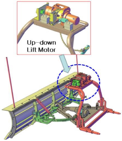
Fig. 1 shows the developed schematic diagram of the snowplow for explanation including the up-down lift motor.
Fig. 1 Schematic diagram of snowplow for explanation of the up-down lift motor
3. Results and Discussion of Snowplow Design
3.1 Design of Left-right Rotator
Fig. 2 shows the designed rotator of the left-right snow blade. Most snowplow blade rotations are a manual hydraulic system with an operator pulling a lever to push the blade out of the car in order to change the blade direction. In the case of the hydraulic system, the rotating speed is too slow due to the heavy weight and the hydraulic fluid temperature dropping in winter as well as the front of the vehicle frequently striking the ground due to the heavy weight of a hydraulic type snowplow. In the case of a wire type snowplow, after a period of time of use, cutting and breakage of the wire occurs due to wire fatigue. The way to solve this problem is through the new design developed in the present study with a specific explanation shown in
Fig. 2.
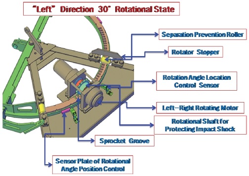
Fig. 2Schematic design of left-right rotator

As shown in
Fig. 2, the rotator of the left-right snow blade consists of many parts such as the separation prevention roller, rotator stopper, rotation angle location control sensor, left-right rotating motor, sprocket groove, sensor plate of the rotational angle position control and the rotational shaft used for protecting against impact shock, similar to an automated driven motor, in order to absorb any external impact. Here, the rotational shaft for protecting against impact shock acts like an automotive clutch that serves to either transmit or block the power when there is an abnormal shock from the snow blade. This design is the focus of the present study and
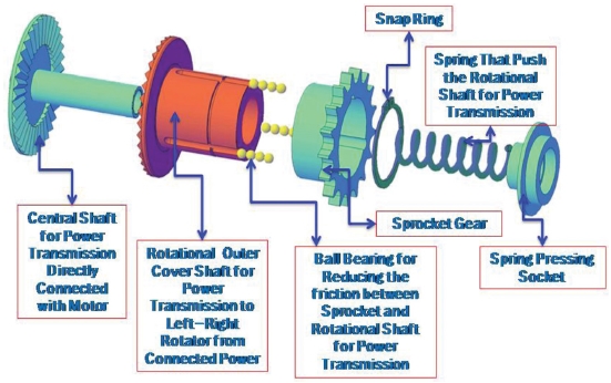
Fig. 3 shows the detailed drawing depicting the rotational shaft.
Fig. 3Rotational shaft detail diagram for protecting impact shock

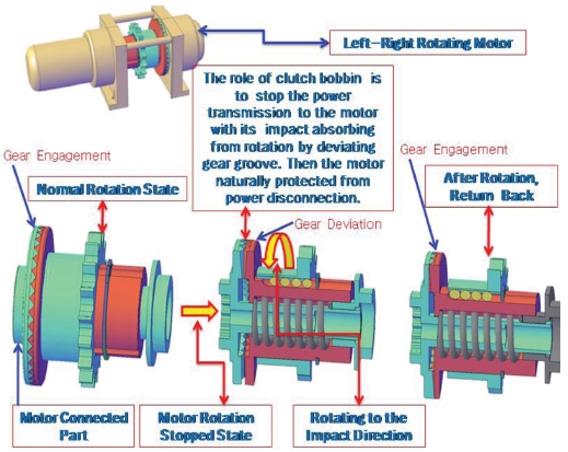
Fig. 4 shows a detailed explanation for the operating principal of the bobbin as an automotive clutch as shown in
Fig. 3. As shown in
Fig. 4, the clutch bobbin is connected to the motor connection part and engages with the snowplow rotating shaft connected gear. While the gear is engaged with another gear rotation, in the event of external shocks arising the from snowplow, the engaged gears are deviated from the push spring. Therefore, though the rotation shaft is rotating to the impact direction, the motor is not rotating because the rotation is not transmitted to the motor by a clutch interception, protecting the motor. This is the core principle of the present study.
Fig. 4Clutch bobbin operating principle for impact shock absorption

3.2 Mounting Height Adjustment Design
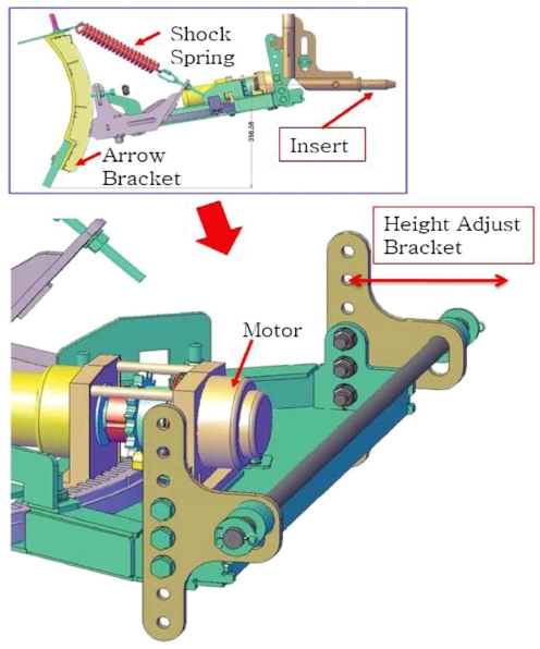
Fig. 5 shows the height adjusting design between the snowplow and vehicle. When the snowplow is mounted to the vehicle, if the snowplow has no height adjusting function, the snowplow mounting is not easy. In addition, a change in the vehicle height can occur following a period of use and cargo weight deformation. To solve this problem, the
Fig. 5 design was developed. Through this design, it can easily match the height pitch when mounting the snowplow to the vehicle. If the holes were perforated at the end of the triangular bracket attached to the back plate bracket, the height could be adjusted easily.
Fig. 5Mounting height adjustment design
3.3 Front-rear Rolling Deflection Protection Design of the Snowplow Rotator
Fig. 6 shows the designed rotator used in order to prevent front and rear rolling deformation. Folding a flat plate twice by 90 degrees to increase stiffness protects deflection; and both nuts and bolts are securely tightened to this arms.
Fig. 6Front-rear rolling deflection protection design of the snowplow rotator
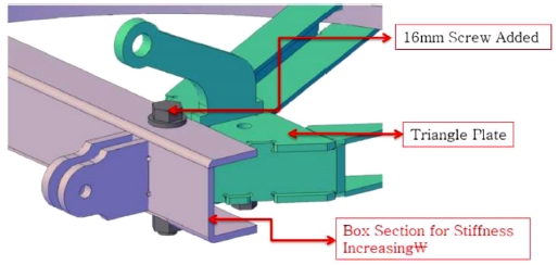
The front-rear rolling deflection protection design was changed as shown in
Fig. 7. As shown in the figure, piece No. ① was added to piece No. ②.
Fig. 8 shows the boundary conditions of the computer simulation. A load of 500 N was given on both ends of the protection member and fixing points are shown. The simulation was conducted by using Nastran-101 (statistical analysis), a well-known commercially used program. The analysis results for before and after design changes were compared, as shown in
Figs. 9(a) and
9(b) and include the analysis models.
Table 1 summarizes the analysis results of
Fig. 9. As shown in
Table 1, the maximum deflection was 1.85 mm before the design change. However, it was lowered about 0.03 mm after design modification in the same loading conditions. Through this, it was found that the deflection degree improves about 62 times. Indicating that the initial protection member model was changed from “ㄴ” type shape to “ㄷ” type shape like box type in order to have higher rigidity.
Fig. 7Cross section region and its magnified shape
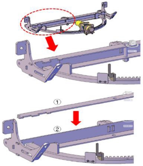
Fig. 8Loads and boundary conditions of snowplow in a static simulation
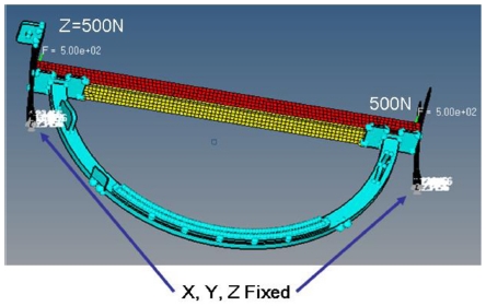
Fig. 9Structural analysis results of snowplow (a) current model and (b) modified model
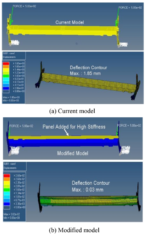
Table 1Static analysis results of snowplow mounting
Table 1
|
Base design |
Modified design |
Max. Stress
(MPa) |
Deflection
(mm) |
Max. Stress
(MPa) |
Deflection
(mm) |
|
277.0 |
1.85 |
13.2 |
0.03 |
Through this design change, the snow removal operation is easy and safe because of increased rigidity and durability when a collision.
3.4 Method of Snowplow Mounting to Vehicle Design
The conventional assembly method between a snowplow and vehicle is used with a hole and pin method in that the hole is mounted on the snowplow and a pin is mounted on the vehicle front as shown in
Fig. 10(a). This approach is dangerous when in a collision because the pin is extruded. To solve this problem, the design of the pin mounted to the snowplow is proposed in the present study as shown in
Fig. 10(b).
Fig. 10Snowplow mounting method to the vehicle, (a) conventional method and (b) newly designed method
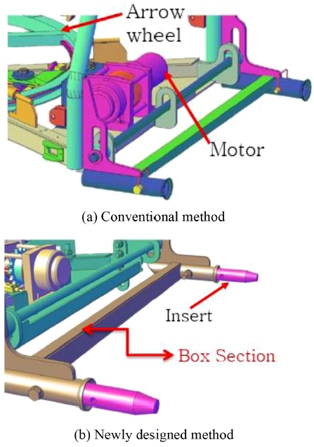
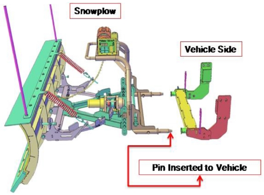
Fig. 11 shows the detailed explanation of the assembly method of
Fig. 10. As shown in
Fig. 11, it is safe to insert a pin across the vehicle equipped with a snowplow.
Fig. 11Explanation of mounting method between snowplow and vehicle

3.5 Design of Snowplow Moving Die
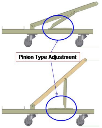
Fig. 12 shows the explanation for the moving die design mounting method use between the snowplow and vehicle. In the case of mounting the snowplow to a low vehicle height, the pipe bracket height can be adjusted as shown in
Fig. 12. In the case of mounting the snowplow to a high vehicle height, it can be also adjusted and is designed as a pinion type adjustment. By using this design, it was convenient to install the snowplow onto the vehicle.
Fig. 12Explanation of mounting method between snowplow and vehicle

Fig. 13 shows the explanation of the ready state between the snowplow and moving die for vehicle mounting. Spinning wheels were used and mounted for 360 degree rotation. This was designed to easily connect the snowplow pin to the vehicle hole by moving the handle operating up and down for the snowplow insert.
Fig. 13Explanation of ready state between snowplow and moving die for vehicle mounting
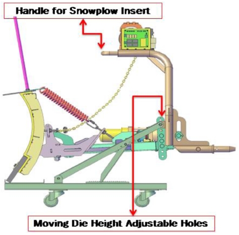
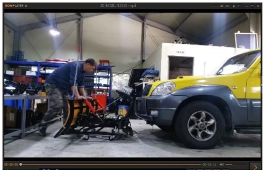
Fig. 14 is the photograph that shows snowplow as it is moved toward the vehicle on the rolling cradle by a man in order to connect together. As a result of measuring a mounting time commissioned by the KIMM (Korean Institute of Machinery and Materials), it took only 69 second from mounting initiation until to the blade pin insert and normal operation.
Fig. 14Photo of snowplow mounting start with moving die

4. Conclusions
1) The torque rotation shaft for protecting against impact is the part that acts similar to an automotive clutch that can transmit or disconnect the power to the shaft. This is the new concept design proposed in the present study. From this method, the durability increases because the external impact was not transmitted to the motor when impact occurred to the snowplow.
2) The variable height adjustable methods for snowplow mounting and the moving die (cradle) was designed and suggested. This cradle makes it possible to mount the snowplow onto the vehicle which can have various heights.
3) The snowplow designed in this study will be commercially available, low-cost with low maintenance costs and excellent durability. Additionally, it will contribute to improving economic efficiency by reducing the number of after service problems.
ACKNOWLEDGMENTS
This paper was presented at PRESM 2018
REFERENCES
- 1.
Park, J.-H. and Kim, K. J., “Optimal Design of Camber Link Component for Light Weight Automobile Using CAE (Computer Aided Engineering),” International Journal of Precision Engineering and Manufacturing, Vol. 14, No. 8, pp. 1433-1437, 2013.
10.1007/s12541-013-0193-9
- 2.
Kim, K. J. and Park, J.-H., “Development of Automated Electric Snowplow by Using Clutch Bobbin for Improving Durability,” Transactions of the Korean Society of Mechanical Engineers A, Vol. 40, No. 11, pp. 949-954, 2016.
10.3795/KSME-A.2016.40.11.949
- 3.
Park, J.-H., Kim, K. J., Lee, J. W., and Toon, J. k., “Light-Weight Design of Automotive Suspension Link Based on Design of Experiment,” International Journal of Automotive Technology, Vol. 16, No. 1, pp. 67-71, 2015.
10.1007/s12239-015-0007-4
- 4.
Kim, K. J., Lee, Y.-C., and Park, J.-H., “Fundamental Research on Power Train Systems for Electric Vehicles: Grundlegende Untersuchungen Zum Antriebsstrang Eines Systems Für Elektrofahrzeuge,” Materialwissenschaft und Werkstofftechnik, Vol. 46, Nos. 4-5, pp. 414-419, 2015.
10.1002/mawe.201500416
- 5.
Park, C. I. and Kim, D.-S., “The Design of a Snow Plow for the Special Equipment Vehicles”, Proc. of KSME Spring Conference, pp. 619-626, 2000.
- 6.
Kwon. J. W., Jang, C., and Hwang, M. W., “A Study on an Optimal Design of Electric Snow Melting Mat for Vulnerable Walk Zone,” Journal of the Korean Society of Safety, Vol. 31, No. 6, pp 12-18, 2016.
- 7.
Salazar-Aguilar, M. A., Langevin, A., and Laporte, G., “Synchronized arc Routing for Snow Plowing Operations,” Computers & Operations Research, Vol. 39, No. 7, pp. 1432-1440, 2012.
10.1016/j.cor.2011.08.014
- 8.
Dur, O. and Evrensel, C. A., “Computational Modeling of Wake Flow to Improve Visibility During High Speed Snow Plowing,” Cold Regions Science and Technology, Vol. 118, pp. 45-56, 2015.
10.1016/j.coldregions.2015.05.006
- 9.
Lysyannikov, А. V., Shram, V. G., and Lysyannikova, N. N., and Лысянникова, Н.Н., “The Optimal Parameters of Installation of the Snow Removing Blade,” Vol. 150, pp. 1176-1181, 2016.
10.1016/j.proeng.2016.07.232
- 10.
Rabiński, M. and Zdunek, K., “Snow Plow Model of IPD Discharge,” Vacuum, Vol. 70, Nos. 2-3, pp. 303-306, 2003.
10.1016/S0042-207X(02)00659-0
- 11.
Perrier, N., Langevin, A., and Campbell, J. F., “A Survey of Models and Algorithms for Winter Road Maintenance. Part IV: Vehicle Routing and Fleet Sizing for Plowing and Snow Disposal,” Computers & Operations Research, Vol. 34, No. 1, pp. 258-294, 2007.
10.1016/j.cor.2005.05.008
- 12.
Kim, K. J., “Fatigue Safety Design of Automotive Suspension Links by Using Computer Aided Engineering Static Analysis: Ermüdungssicherheitsentwurf Von Fahrzeugaufhängungen Mit Hilfe Einer Rechnergestützten Statischen Analyse,” Materialwissenschaft Und Werkstofftechnik, Vol. 49, No. 5, pp. 619-626, 2018.
10.1002/mawe.201700237
Biography
- Kee Joo Kim
Professor in the School of Mechatronics Engineering, Tongmyung University. He specialized in mechanical engineering in school years. He has experience to work in Ssangyong Motor Co. for about 16 years.
- Si Tae Won
Professor in the Department of Mechanical System Design Engineering, Seoul National University of Science and Technology. He worked at the university for 34 years.
Citations
Citations to this article as recorded by