ABSTRACT
We propose the measurement method for location errors in a horizontal 4-axis machine tool using a touch trigger probe and a sphere artifact. Location errors (type of geometric errors), are values that do not change with the position of each feed axis because these errors are usually fixed in an assembly procedure. There are seven location errors in a horizontal 4-axis machine tool; three squareness errors in three linear axes and two squareness and two offset errors in a rotary axis. The positions of center point of sphere artifact on a rotary axis are measured by a touch trigger probe mounted on a tool axis. Because measured center points are expressed by seven location errors via the homogeneous transformation matrix, location errors can be separated by analyzing measured data. To validate the proposed method, measurement experiments were performed on a horizontal 4-axis machine tool. Measurement results were verified by comparing before and after compensation.
-
KEYWORDS: Horizontal machine tool, Location error, Touch trigger probe, Sphere artifact, Homogeneous transformation matrix
-
KEYWORDS: 수평형 공작기계, 위치오차, 터치트리거프로브, 기준구, 동차변환행렬
1. 서론
공작기계의 기하오차(Geometric Errors)는 요소오차(Component Errors)와 위치오차(Location Errors)로 구분된다.
1 요소오차는 각 이송축 자체의 6자유도 운동오차(Motion Error)로서,
2 레이저 간섭계,
3,4 스트레이트 엣지
2,5 및 다수의 변위센서를 이용한 자가 보정법
6-8을 이용하여 비교적 쉽게 측정할 수 있다. 하지만, 직각도 오차와 오프셋 오차와 같은 위치오차
2는 각 이송축의 위치에 따라 오차값이 변하지 않고 공작기계의 조립과정에서 작업자의 숙련도에 영향을 많이 받는다.
9,10 또한, 위치오차는 공작기계가 조립된 후 다축 동시제어가 되는 조건에서 측정해야 되므로 요소오차보다 측정이 어렵다.
1
다축 공작기계의 위치오차는 일반적으로 볼바를 이용한 원호측정방법으로 규명한다.
10-12 하지만, 측정 스트로크가 제한되고,
1 회전축과 직선축의 위치오차는 분리하여 측정해야 한다.
12 R-Test
13-15를 이용한 측정방법은 주로 회전축과 관련된 위치오차측정을 위해 적용되지만,
14 직선축의 직각도 오차를 함께 측정하기 위해서는 다수의 측정 셋업이 필요하다는 단점이 있다.
15 터치 트리거 프로브(이하 터치프로브)와 기준물을 이용한 측정방법
16-19은 직선축의 위치오차를 무시할 수 있다는 가정하에 회전축의 위치오차를 측정하거나,
17 회전축의 중심 오프셋 오차만 측정할 수 있다는 단점이 있다.
18 또한, 가공테스트를 이용한 방법
20,21은 다수의 패턴이 가공된 육면체 공작물의 치수정확도를 측정하여 위치오차를 규명할 수 있지만, 공작물이나 공구의 자세를 여러 번 변경해야만 한다.
대부분의 위치오차 측정방법들은 회전축의 위치오차 측정에 집중하였다. 또한, 직선축과 회전축의 모든 위치오차 측정을 위해 개발된 측정방법들은 다수의 측정셋업을 필요로 하고, 측정 자세를 쉽게 변경시킬 수 있는 5축 공작기계를 기반으로 개발되었다. 따라서, 공작물의 자세를 변경시키기 어려운 4축 공작기계에서는 기존의 측정방법을 이용해서는 장비의 모든 위치오차를 측정할 수 없다. 특히, 수평형 공작기계의 경우, 회전축의 위치에 따라 공구의 접근성이 떨어지고 공작물과의 간섭현상이 발생하므로 장비 특성을 고려한 측정방법의 수정이 필요하다.
본 연구에서는 터치프로브와 기준구를 이용한 저자들의 기존 방법
19을 수평형 4축 공작기계에 확대 적용하여 위치오차를 측정하였다. 수평형 4축 공작기계의 경우 구조적으로 공작물의 높이를 조절하지 못하므로 기준구의 설치 높이를 변경하여 높이와 연관된 위치오차를 측정하였고, 터치프로브의 접근성 제한 문제를 해결하기 위해 터치프로브에 연장지그를 사용하여 측정하였다.
수평형 4축 공작기계에서 기준좌표계에 대해 총 7개의 위치 오차를 정의하고, 회전축을 일정 간격으로 이송시키며 회전축 위에 설치된 기준구의 중심점을 터치프로브를 이용하여 측정하였다. 이때 기준구의 중심점 측정값은 기 정의한 7개의 위치오차로 표현되므로 이를 분리할 수 있는 알고리즘을 개발하였다. 알고리즘의 검증을 위해 수평형 4축 공작기계의 기하오차를 측정하고, 측정된 기하오차 중 직각도 오차와 오프셋 오차는 제어기를 이용하여 보정한 후 보정 전/후의 결과를 비교하여 제안된 방법을 검증하였다.
2. 수평형 4축 공작기계 위치오차 측정원리
2.1 수평형 4축 공작기계 위치오차 정의 및 기구학적 모델링
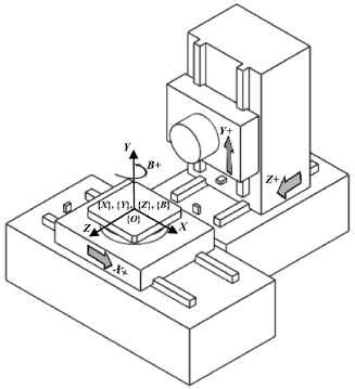
Fig. 1은 본 논문에서 대상으로 하고 있는 수평형 4축 공작기계의 레이아웃으로, 세 개의 직선축(
X,
Y,
Z축)과 하나의 회전축(
B축)으로 구성되어있다. 이러한 다축 공작기계의 위치오차는 이웃한 두 이송축의 로컬좌표계 간의 초기위치와 방향에 대한 관계를 나타내며, 공작기계 기준좌표계 설정과 밀접한 관계가 있다.
22
Fig. 1Layout of a horizontal 4-axis machine tool

공작기계의 실제 직선축(
Xactual,
Yactual,
Zactual)은
Fig. 2(a)와 같이 공간상에서 이상적인 직선축(
Xideal,
Yideal,
Zideal)에 대해 각 축당 두 개의 각도성분이 정의되므로 세 직선축에서 총 6개의 각도성분이 존재한다. 그러나 기준좌표계를 이상적인 축이 아닌 실제 이동한 축에 대응하여 기준좌표계를 설정하는 것에 의해 3개의 직각도 오차로 줄일 수 있다. 기준좌표계(
Xref,,
Yref,
Zref.)의 원점({
O})은
Fig. 1에 표시한 것과 같이,
X 이송축의 중간 위치에 있는 초기위치의 회전축 중심에 정의하고
X축(
Xref.)은
Fig. 2(a)와 같이 공작기계의 실제
X이송축과 일치시켰다. 이
X축과 지표면에 대해 직각을 이루는 축을 기준좌표계의
Z축(
Zref.)으로 정의한 뒤 이
Xref.-
Zref. 축을 토대로 오른손 좌표계에 따라
Yref. 축을 정의하였다. 또한 모든 이송축의 로컬좌표계의 원점을 기준 좌표계의 원점에 일치시켜 각 로컬좌표계 원점 간 거리를 무시하였다.
Fig. 2Location errors in 4-axis machine tool
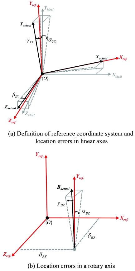
이 기준좌표계를 바탕으로 세 직선축 사이의 위치오차는
Fig. 2(a)와 같이 총 세 개의 직각도 오차(
αYZ,
βZX,
γYX)로 정의할 수 있다. 또한, 회전축의 위치오차는 실제 회전축의 평균선(
Bactual)과 기준좌표계의 초기위치와 평행관계로부터
Fig. 2(b)와 같이 두 개의 직각도 오차(
αBZ,
γBX)와 두 개의 오프셋 오차(
δBX,
δBZ)가 정의된다. 따라서,
Fig. 1의 4축 공작기계에서는 총 7개의 위치오차가 정의되고 각 위치오차에 대한 설명은
Table 1에 정리하였다. 여기서, 직각도 오차의 기호는 회전 중심축에 따라 각각
α,
β, 및
γ로 정의하였고, 오프셋 오차는
δ로 정의하였다. 각 위치오차의 하첨자는 오차가 발생하는 두 기준축을 나타내며, 모든 위치오차의 방향은 오른손 좌표계를 기준으로 한다. 또한 기준좌표계를 기준으로
Fig. 1의 공작기계의 공구에서부터 공작물까지 기구학적 구조는 [(
t)-
Y-
Z-(
O)-
X-
B-(
w)]와 같이 표현할 수 있다. 여기서,
t,
O 및
w는 공구, 기준좌표계의 원점 및 공작물을 나타낸다.
Table 1Location errors in a 4-axis machine tool
Table 1
|
Symbol |
Explanation |
|
α
YZ
|
Squareness error between Z and Y-axis |
|
β
ZX
|
Squareness error between X and Z-axis |
|
γ
YX
|
Squareness error between X and Y-axis |
|
α
BZ
|
Squareness error between B and Z-axis |
|
γ
BX
|
Squareness error between B and X-axis |
|
δ
BX
|
Offset error of B-axis in X-direction |
|
δ
BZ
|
Offset error of B-axis in Z-direction |
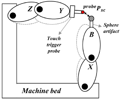
Fig. 1의 4축 공작기계의 공구축에 터치프로브를 장착하고 공작물축에 기준구를 설치하여 기준구의 중심점을 측정하는 경우, 앞서 언급한 기구학적 구조에서 공구(
t)와 공작물(
w)을 터치프로브(
probe)와 기준구 중심점(
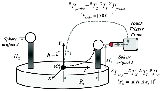
sc)으로 각각 대체하여 표현할 수 있다. 기준좌표계 원점에서 터치프로브와 기준구까지의 위치는
Fig. 3과 같이 공작기계를 강체구조로 가정하여 동차변환행렬(
RTX XTB BPsc , RTZ ZTY YPprobe)로 각각 계산할 수 있으며, 이로부터 터치프로브가 측정한 기준구 중심점의 위치를 유도할 수 있다.
19 여기서,
R,
H 및 Δ
wz는 각각 회전반경, 기준구 높이 및
Z 방향 기준구 설치오차이며, 기준구의 설치오차 중
X방향 설치오차는 반경(
R)에 포함되므로
Z방향 설치오차만 고려하였다. 또한, 공작기계의 각 이송축의 요소오차는 무시 할 수 있는 수준으로 미리 보정되었다고 가정하였다. 동차변환행렬의 유도과정은 저자들의 기존연구
19와 중복되므로 본 논문에서는 생략하였다. 본 연구에서처럼 수평형 공작기계에서는 기준구 1과 2는 동시에 사용할 수 없으므로,
Fig. 3에서 기준구 2의 의미는 기준구 1의 높이를 변경하여 사용한다는 것을 의미한다.
Fig. 3Measurement principle of location errors

터치프로브로 측정된 기준구의 중심점은 세 직선 이송축이 기준구 중심점을 측정하기 위해 이송한 값이라는 의미를 갖는다. 터치프로브로 측정한 기준구 중심점(
mreal)은 기준구 중심위치와 터치프로브의 위치가 일치한다는 원리(
RPsc=
RPprobe)로 쉽게 구할 수 있다. 앞서 정의한 7개의 위치오차로 인해
Fig. 4와 같이 터치프로브와 기준구 사이의 오차벡터(
probePsc)가 발생한다. 하지만, 터치프로브가 기준구 중심을 측정하기 위해서는 기준구 중심점과 터치프로브가 반드시 일치해야 하기 때문에, 직선 이송축은 이 오차벡터만큼 추가적으로 이송되어야 한다. 따라서, 실제 기준구 중심점 측정값(
mreal)은
식(1)과 같이 위치오차가 존재하지 않는 이상적인 경우의 기준좌표계 원점에서 기준구 중심점까지의 직선축의 이송량(
mideal)에 터치프로브와 기준구 사이의 오차벡터(
probePsc)에 해당하는 추가이송량(
Δm)을 더하여 유도할 수 있다. 단,
Fig. 1과 같은 구조의 공작기계에서 터치프로브는
X방향으로 이동하지 못하므로,
X방향 추가이송량은 오차벡터의 반대부호가 된다.
Fig. 4Error vector between the sphere artifact and the probe

where, ∆m=-Psc,xprobePsc,yprobePsc,zprobeT
2.2 위치오차 분리 수식 유도
회전축(
B축)의 1회전(360도)을 정수(
N)로 분할한 일정한 각도(
b도)로 회전시켜가며 기준구 중심점을 측정한다고 할 때,
식(2)와
식(3)의 삼각함수의 특성을 이용할 수 있다. 이 특성을 기준구 중심점 측정값에 적용하여 수평형 4축 공작기계의 7개 위치오차를 모두 분리할 수 있는 수식을 유도하였다.
where, bj=b⋅j-1b=360N,j=1,…,N
위치오차를 분리하기 위해 먼저 회전반경(
R)과 설치오차(
Δwz)를 실제 기준구 중심점 측정값으로부터
식(4),
식(5)과 같이 유도하였다. 회전반경(
R)은
X방향 중심점 측정값(
mreal,x)과
Z방향 중심점 측정값(
mreal,z)에 cos(
b)와 sin(
b)를 각각 곱하여
식(3)의 삼각함수 특성을 이용하여 분리하였다. 또한, 설치오차(
Δwz)도
Z방향 중심점 측정값(
mreal,z)에 sin(
b)를 곱하여 동일한 방법으로 분리하였다.
이미 구해진 회전반경(R)과 설치오차(Δwz)를 이용하여 X와 Z축 간 직각도 오차(βZX)를 구하면 다음과 같다.
B축의 두 직각도 오차(
αBZ,
γBX)는
Y방향 중심점 측정값(
mreal,y)에 커플링되어 있으므로
Y방향 측정값에 cos(
b)와 sin(
b)를 각각 곱하여
식(3)의 특성을 이용하여 두 식을 만든 뒤 회전반경(
R)과 설치오차(
Δwz)을 이용하여 연립하여 각각 구할 수 있다.
다른 직선축 사이의 직각도 오차와 회전축의 오프셋 오차는 하나의 기준구 측정값으로는 구할 수 없다. 이 오차들은 높이가 다른 두 개의 기준구 중심점 측정값을 이용하여 구할 수 있다. 두 기준구 중심점 측정값(
mreal,1,
mreal,2)에
식(2)의 특성을 적용하여 1회전 평균값(
m¯)을 구하면
식(9)와 같이 나타낼 수 있다. 여기서, 하첨자
i는
Fig. 3에서 표시한 각 기준구의 번호를 나타내고,
Y방향 중심점 측정값을 평균하여 각 기준구의 높이(
H1,
H2)를 구할 수 있다. 두 기준구의 높이를 이용하면, 두 직선축 직각도 오차(
αYZ,
γYX)와 회전축의 두 오프셋 오차(
δBX,
δBZ)는
식(10)에서
식(13)으로 계산된다.
정리하면, 수평형 4축 공작기계에서 정의된 7개의 오차 중, X와 Z축 간 직각도 오차(βZX)와 B축의 두 직각도 오차(αBZ, γBX)는 기준구 하나의 측정값으로부터 계산 가능하며, 나머지 4개의 오차는 높이가 다른 두 기준구의 측정값이 있어야만 분리할 수 있다.
3. 측정실험 및 결과
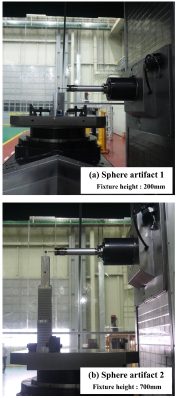
본 논문에서 제안한 위치오차 분리 알고리즘 검증을 위해
Fig. 1과 같은 구조로 구성된 수평형 4축 공작기계에서 실험을 수행하였다. 수평형 공작기계에서 터치프로브의 접근성 제한 문제를 해결하기 위해 연장지그(길이 250 mm)를 이용하였으며, 기준구의 설치높이를 200 mm와 700 mm로 하여 회전축 위에 설치하였다. 실험에 사용된 기준구는 직경 19 mm(진구도 0.1 μm)이고 터치프로브는 Renishaw사의 RMP-600 (3차원 측정 분해능 1 μm)이 사용되었다. 터치프로브의 리시버는 공작기계의 제어기(FANUC Panel i)에 연결되어 터치프로브가 기준구와 접촉할 때, 세 직선축의 위치(스케일 값)를 자동으로 기록하였다. 회전축의 회전각도(
b)는 측정시간을 고려하여 45도로 설정하였다.
Fig. 5 Experimental setup for horizontal 4-axis machine tool

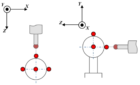
수직형 공작기계와는 다르게 수평형 공작기계의 경우, 터치프로브의 반대편 기준구의 위치는 측정하지 못하기 때문에
Fig. 6처럼 4점만을 이용하여 기준구 중심점을 계산하였다. 측정프로그램에 의해 기준구의 각 측정위치에서 터치프로브는 기준구 주위 4점을 측정하고 기준구 중심점을 자동으로 계산하여 파일로 저장하였다. 각 높이에서 측정한 기준구 중심점을
식(4)부터
식(13)에 대입하여 회전반경(
R), 설치오차(
Δwz), 각 기준구 높이(
H1,
H2) 및 7개의 위치오차를 각각 계산하여
Table 2에 나타내었다. 총 3번 측정한 결과, 측정된 직각도 오차와 오프셋 오차의 최대 반복능은 각각 ± 1.34 μrad와 ± 0.61 μm 수준으로 나타났다.
Fig. 6 Measurement points for calculating the center position of a sphere artifact

Table 2 Experimental results
Table 2
|
R
|
Δwz
|
H
1
|
H
2
|
αYZ
|
βZX
|
γYX
|
αBZ
|
γBX
|
δBX
|
δBZ
|
|
unit |
mm |
mm |
mm |
mm |
μrad |
μrad |
μrad |
μrad |
μrad |
μm |
μm |
|
Exp.1 |
218.0956 |
-1.3493 |
241.7629 |
741.7414 |
-17.06 |
-10.59 |
-0.44 |
-4.56 |
-8.96 |
2.86 |
-7.11 |
|
Exp.2 |
218.0955 |
-1.3495 |
241.7634 |
741.7422 |
-17.49 |
-10.43 |
-0.73 |
-5.01 |
-9.13 |
3.33 |
-7.34 |
|
Exp.2 |
218.0955 |
-1.3492 |
241.7633 |
741.7432 |
-17.43 |
-9.36 |
-1.10 |
-4.90 |
-10.18 |
2.76 |
-7.24 |
|
Avg. |
218.0955 |
-1.3493 |
241.7632 |
741.7423 |
-17.33 |
-10.13 |
-0.76 |
-4.82 |
-9.42 |
2.98 |
-7.23 |
|
2sigma |
±0.0001 |
±0.0004 |
±0.0006 |
±0.0018 |
±0.47 |
±1.34 |
±0.66 |
±0.47 |
±1.32 |
±0.61 |
±0.23 |
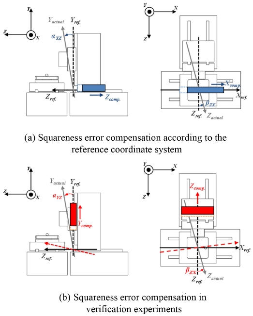
이 측정결과를 검증하기 위해 직선축의 직각도 오차와 회전축의 오프셋 오차 보정실험을 수행하였다.
Table 2의 위치오차 측정결과를 기반으로 제어기 보정값을 설정하여 직선축의 기울기와 회전축 중심점을 보정한 뒤 동일한 측정실험을 수행하였다. 직각도 오차 보정에 사용한 방법은
Fig. 7과 같이 서로 직각인 두 개의 축 중 하나를 기준축으로 설정하고, 다른 축을 보정축으로 설정하여 직각도 오차에 의해 완전히 직각으로 움직이지 못하는 양을 보정축을 추가로 움직여서 직각으로 만들어주는 원리이다.
23 본 논문에 사용된 제어기의 경우 제조사에서 보정 기능을 제공하지 않아 공작기계 사용자가 각 축의 진직도 오차와 두 축간의 직각도 오차를 보정하기 위해 자체적으로 프로그램 한 것을 사용하였고, 이로 인해
Fig. 7(b)와 같은 직각도 보정 방법을 적용하였다. 회전축 오프셋 오차의 경우는 이 오차만큼 제어기에서 회전축 중심점 좌표를 변경하여 보정하였다.
Fig. 7 Squareness error compensation method

보정실험 시 제어기에 입력한 직선축 기울기 보정값은
Z-
Y축 간 직각도 오차(
αYZ)를 보정하기 위해
Z-
Y축 간 기울기 -1.2 μm/100 mm(
αcomp.)를 이용하였고,
X-
Z축 간 직각도(
βZX)를 보정하기 위해
X-
Z축 간 기울기 1.3 μm/100 mm(
βcomp.)를 이용하였다. 여기서,
αcomp 및
βcomp는 각각
Z-
Y축 간 직각도 오차와
X-
Z축 간 직각도 오차를 보정하기 위해 사용된 실제 보정 각도를 의미하며, 각 오차에 대한 보정
식(14)와 같다. 단,
X-
Y축 간 직각도 오차(
γYX)는 오차량이 1 μrad 미만이기 때문에 보정을 적용하지 않았다.
회전축 오프셋 오차의 경우, 보정값은
X방향으로 -3 μm,
Z방향으로 7.3 μm을 적용하였다. 이렇게 보정값을 적용하여 보정실험을 2회 반복하여 진행하였고, 보정 전후의 위치오차 결과 비교를 위해 측정된 위치오차의 평균값을
Table 3에 나타내었다.
Table 3 Comparison the experiment results before and after compensation
Table 3
|
αYZ
|
βZX
|
γYX
|
αBZ
|
γBX
|
δBX
|
δBZ
|
|
Before |
-17.33 |
-10.13 |
-0.76 |
-4.82 |
-9.42 |
2.98 |
-7.23 |
|
After |
6.91 |
5.36 |
6.15 |
-1.09 |
-1.86 |
1.28 |
3.14 |
보정 전/후의 결과를 비교하면, 직선축 기울기 보정과 회전축 중심점 보정이 적용된 직선축의 두 직각도 오차(αYZ, βZX)와 회전축의 오프셋 오차(δBX, δBZ)는 보정값만큼 완벽히 보정된 것은 아니지만 모두 감소하는 경향을 보였다. 하지만, 직선축 기울기와 회전축 중심점 보정만 진행하였는데도 불구하고, 보정으로 회전축의 직각도 오차(αBZ, γBX)가 변하였고, 보정값을 입력하지 않은 X-Y축 간 직각도 오차(γYX)도 약 7 μrad 정도가 증가하였다.
이 문제에 대한 가장 근본적인 원인은 직선축 기울기보정으로 인한 기준좌표계의 위치변화로 볼 수 있다. 2.1절에서 수평형 4축 공작기계의 위치오차는 장비 이송축을 기준으로 설정된 기준좌표계를 기반으로 정의되었기 때문에, 직선축 기울기 보정도 기준좌표계를 기반으로 수행되어야 한다. 따라서,
Fig. 7(a)와 같이
Z-
Y축 간 직각도(
αYZ)와
X-
Z축 간 직각도(
βZX)는 각각
Z축과
X축을 이송시켜 직각도 오차가 발생하는 두 축의 직각 성분을 보정해야 한다. 하지만, 실험에 사용된 공작기계의 제어기 보정 프로그램은 진직도 오차와 직각도 오차 보정을 동시에 사용하여 보정 입력 방법에 제한이 발생하였고, 이러한 이유로 두 직각도 오차(
αYZ,
βZX)는
Fig. 7(b)와 같이
Y축과
Z축을 각각 이송시켜 보정할 수 밖에 없었다.
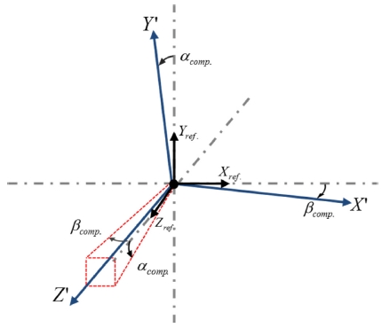
이렇게 직선축의 기울기 보정이 적용된
X′ 축을 기준으로 기준좌표계를 다시 설정하면
Fig. 8과 같이 기준좌표계가 (
X′-
Y′-
Z′)축으로 재정의된다.
Fig. 8 Reference coordinate system changed by the compensation

따라서 새로운 기준좌표계로 인해 보정값이 적용되지 않은 X-Y축 간 직각도 오차(γYX)도 바뀌게 된 것으로 보인다. 또한, 새로운 기준좌표계와 B축 간의 평행관계가 바뀌게 되고, 이 영향으로 보정 전/후의 B-Z축 간 직각도 오차(αBZ)와 B-X축 간 직각도 오차(γBX) 결과값이 다르게 측정된 것으로 판단된다.
그러나 이와 같은 문제는 본 논문에서 대상으로 하는 제어기의 오차 보정 프로그램의 한계로 인해 발생하는 현상으로, 추후 위치오차 모델링을 위한 기준좌표계와 보정을 위한 좌표계를 일치시키는 방법에 의해 개선할 수 있을 것이다.
4. 결론
본 연구에서는 수평형 4축 공작기계에서 위치오차를 측정하기 위해 터치프로브와 기준구를 이용한 측정방법을 제안하고 실제 공작기계를 대상으로 측정 및 검증하였다.
수평형 4축 공작기계에서 정의된 7개의 위치오차는 회전테이블에 설치된 기준구의 중심점 좌표로 표현되므로, 스핀들에 설치된 터치프로브를 이용하여 기준구의 서로 다른 위치에서 이를 측정하고, 이로부터 기준구의 회전반경, 설치오차, 기준구의 높이 및 7개의 위치오차를 분리하는 알고리즘을 개발하였다. 4축 공작기계의 구조상 높이방향으로는 측정위치를 변화시키기 어렵기 때문에 기준구의 설치높이를 달리하여 높이 방향과 관련된 위치오차를 분리하였다.
제안된 측정방법을 검증하기 위해 실제 수평형 4축 공작기계를 대상으로 측정실험을 하였다. 이때 수평형 장비의 특성상 터치프로브의 접근성을 향상시키기 위해 연장지그를 이용하였고, 기준구의 4점만을 이용해서 중심점 좌표를 측정하였다. 측정결과의 검증을 위해 측정된 위치오차를 이용하여 직선축 기울기와 회전축 중심점을 보정하여 보정 전/후의 실험결과를 비교하였다. 보정 후, 직선축의 직각도 오차는 -17.3 μrad에서 6.9 μrad으로, 회전축의 오프셋 오차는 -7.2 μm에서 3.1 μm로 감소하는 것을 확인하였다.
본 논문에서 제안된 측정방법은 수평형 4축 공작기계에서 7개의 위치오차와 더불어 기준구의 설치오차 및 반경, 높이 등도 함께 분리가 가능하기 때문에 설치 시 숙련된 기술이 필요 없고, 두 번의 측정 셋업에 의해, 각각은 자동 측정프로그램에 의해 20분 내에 측정이 완료된다. 따라서 제안된 위치오차 측정방법은 수평형 4축 공작기계에서 위치오차의 주기적인 진단 및 보정에 유용하게 활용할 수 있을 것으로 기대된다.
ACKNOWLEDGMENTS
본 연구는 산업통상자원부의 산업핵심기술개발사업(No. 10052978) 및 한국기계연구원의 주요사업(NK213F)의 지원으로 수행되었습니다.
REFERENCES
- 1.
Schwenke, H., Knapp, W., Haitjema, H., Weckenmann, A., Schimitt, R., et al., “Geometric Error Measurement and Compensation of Machines-An Update,” CIRP Annals, Vol. 57, No. 2, pp. 660-675, 2008.
10.1016/j.cirp.2008.09.008
- 2.
ISO 230-1, “Test Code for Machine Tools-Part I: Geometric Accuracy of Machines Operating under No-Load or Quasi-Static Conditions,” 2012.
- 3.
Hewlett Packard Co., “Laser Measurement System User's Guide, Manual,” No. 00528-90010, 1984.
- 4.
Gao, W., Arai, Y., Shibuya, A., Kiyono, S., and Park, C. H., “Measurement of Multi-Degree-of-Freedom Error Motions of a Precision Linear Air-Bearing Stage,” Precision Engineering, Vol. 30, No. 1, 96-103, 2006.
10.1016/j.precisioneng.2005.06.003
- 5.
Sartori, S. and Zhang, G. X., “Geometric Error Measurement and Compensation of Machines,” CIRP Annals, Vol. 44, No. 2, pp. 599-609, 1995.
10.1016/S0007-8506(07)60507-1
- 6.
Tanaka, H., Tozawa, K., Sato, H., O-hori, M., and Sekiguchi, H., “Application of a New Straightness Measurement Method to Large Machine Tool,” CIRP Annals, Vol. 30, No. 1, pp. 455-459, 1981.
10.1016/S0007-8506(07)60977-9
- 7.
Tanaka, H. and Sato, H., “Extensive Analysis and Development of Straightness Measurement by Sequential-Two-Points Method,” Journal of Engineering for Industry, Vol. 108, pp. 176-182, 1986.
10.1115/1.3187061
- 8.
Park, C. H., Oh, Y. J., Shamoto, E., and Lee, D. W., “Compensation of five DOF Motion Errors of Hydrostatic Feed Table by Utilizing Actively Controlled Capillaries,” Precision Engineering, Vol. 30, No. 3, pp. 299-305, 2006.
10.1016/j.precisioneng.2005.10.002
- 9.
Yang, S., Lee, H., and Lee, K., “Interim Check and Compensation of Geometric Errors to Improve Volumetric Error of Machine Tools,” Journal of the Korean Society for Precision Engineering, Vol. 35, No. 6, pp. 623-627, 2018.
10.7736/KSPE.2018.35.6.623
- 10.
Lee, K. and Yang, S., “Compensation of Position-Independent Geometric Errors of an Index Table by Linear Axes Circular Tests at Different Angular Positions,” International Journal of Advanced Manufacturing Technology, Vol. 84, Nos. 5-8, pp. 981-988, 2016.
- 11.
Xiang, S., Yang, J., and Zhang, Y., “Using a Double Ball Bar to Identify Position-Independent Geometric Errors on the Rotary Axes of Five Axis Machine Tools,” International Journal of Advanced Manufacturing Technology, Vol. 70, Nos. 9-12, pp. 2071-2082, 2014.
10.1007/s00170-013-5432-9
- 12.
Tsutsumi, M. and Saito, A., “Identification and Compensation of Systematic Deviations Particular to 5-Axis Machining Centers,” International Journal of Machine Tools and Manufacture, Vol. 43, No. 8, pp. 771-780, 2003.
10.1016/S0890-6955(03)00053-1
- 13.
- 14.
Weikert, S., “R-Test, A New Device for Accuracy Measurement on Five Axis Machine Tools,” CIRP Annals, Vol. 53, No.1, pp. 429-432, 2004.
10.1016/S0007-8506(07)60732-X
- 15.
Hong, C., Ibaraki, S., and Oyama, C., “Graphical Presentation of Error Motions of Rotary Axes on a Five-Axis Machine Tool by Static R-Test with Separating the Influence of Squareness Errors of Linear Axes,” International Journal of Machine Tools and Manufacture, Vol. 59, pp. 24-33, 2012.
10.1016/j.ijmachtools.2012.03.004
- 16.
Kim, K. and Chung, S., “Synthesis of the 3D Artefact for Quick Identification of Thermal Errors in Machine tools,” International Journal of Production Research, Vol. 42, No. 6, pp. 1167-1187, 2004.
10.1080/00207540310001614123
- 17.
Ibaraki, S., Iritani, T., and Matsushita, T., “Calibration of Location Error of Rotary Axes on Five-Axis Machine Tools by on-the-Machine Measurement Using a Touch-Trigger Probe,” International Journal of Machine Tools and Manufacture, Vol. 58, pp. 44-53, 2012.
10.1016/j.ijmachtools.2012.03.002
- 18.
- 19.
Jeong, J. H., Khim, G., Oh, J. S., and Chung, S., “Method for Measuring Location Errors Using a Touch Trigger Probe on Four-Axis Machine Tools,” The International Journal of Advanced Manufacturing Technology, Vol. 99, Nos. 1-4, pp. 1003-1012, 2018.
10.1007/s00170-018-2506-8
- 20.
Jiang, Z., Song, B., Zhow, X., Tang, X., and Zheng, S., “On-Machine Measurement of Location Errors on Five-Axis Machine Tools by Machining Tests and a Laser Displacement Sensor,” International Journal of Machine Tools and Manufacture, Vol. 95, pp. 1-12, 2015.
10.1016/j.ijmachtools.2015.05.004
- 21.
Yang, H., Huang, X., Ding, S., and Yang, Y., “Identification and Compensation of 11 Position-Independent Geometric Errors on Five-Axis Machine Tools with a Tilting Head,” International Journal of Machine Tools and Manufacture, Vol. 94, pp. 533-544, 2018.
10.1007/s00170-017-0826-8
- 22.
Lee, D., “Error Evaluation Techniques for Geometric Errors of a Multi-Axis Machine Tool Using a Ballbar System,” Ph.D. Thesis, Kyungpook National University, 2011.
- 23.
Biography
- Ji Hun Jeong
Ph.D. candidate in the School of Mechanical Engineering, Hanyang University. His research interests are Precision machines and Metrology.
- Gyungho Khim
Principal researcher in Korea Institute of Machinery & Materials (KIMM). His research interests are Precision machine design and Simulation technology.
- Jeong Seok Oh
Principal researcher in Korea Institute of Machinery & Materials (KIMM). His research interests are Precision machines and Metrology.
- Sung-Chong Chung
Professor in the School of Mechanical Engineering, Hanyang University. His research interest are CAD/CAM, Control, Mechatronics, Manufacturing and Precision engineering.