ABSTRACT
In this work, we present an experimental study on cutting force and chip shrinkage coefficient during the milling of SKD11 steel at elevated temperatures using a high-frequency induction heating method. To improve the determination of the chip shrinkage coefficient, a 3D scanning method incorporating GOM Inspect 3D data analysis software was used to measure the chip length. To evaluate the effect of the heating process on output data such as chip geometry, cutting force, and chip shrinkage coefficient, cutting experiments were conducted at room and elevated temperatures with the same machining parameters of cutting speed, feed rate, and cutting depth. The Taguchi orthogonal array method was subsequently used for experimental design to obtain optimum values of the machining parameters. The analysis of variance method was also performed to indicate the percentage effect of the machining parameters on the cutting force and chip shrinkage coefficient. Finally, models of the cutting force and chip shrinkage coefficient during thermal-assisted milling of SKD11 were established and compared with experimental data.
-
KEYWORDS: Cutting force, Chip shrinkage coefficient, Thermal – Assisted machining, Induction heating, SKD11 steel
NOMENCLATURE
The synthetic cutting force
Three the cutting forces components
The uncut and actual chip length
Cutting speed, feed rate, cutting depth
Chip shrinkage coefficient
Destiny of the workpiece material
1. Introduction
Presently, advanced materials show high hardness, less abrasive wear resistance, and thermal conductivity when subjected to elevated temperatures. Moreover, advanced machining methods such as electro-discharge machining, grinding by abrasive diamond, etc., have been developed. However, these machining methods are limited because of low machining productivity due to low material removal rate, expensive tools, fast tool wear, and high machining time.
1,2 Thermal-assisted machining (TAM) is one of the new technological solutions, which supports the cutting process to increase machining productivity, improve surface quality, and reduce cost. Although this method improves machinability, it does not change the material’s mechanical properties after the heating process. In TAM, a material is softened, thereby leading to its hardness reduction.
3
Baili et al.
4 studied the improvement of machinability of Ti-5553 alloy during thermal-assisted turning by a magnetic induction heat source. Studies showed that the cutting force was reduced by 34.4% when the workpiece temperature reached 750
oC. Ginta et al.
5 presented the effect of heating process on the cutting ability of Ti-6Al-V4 alloy during thermal-assisted milling on vertical milling machines. The authors showed that the cutting force, vibration, tool life, and material removal rate is affected by a direct heating process on the machining workpiece. In TAM, a decrease in the cutting force will lead to a reduction of stress on the cutting tool, thereby increasing the tool life and decreasing the vibration of the cutting process. Chip geometry changes when material strength is reduced as proven by Sun et al. during laser-assisted milling of Ti-6Al-V4 alloy.
6 The authors found that chips were segmented in conventional machining. However, the affection of laser heat source, which lead to the reduction of the cutting force, was a significant cause of the transition from segmented to continuous chips in TAM. Chip shrinkage coefficient is an important parameter to evaluate the plasticity deformation of a material. The chip shrinkage coefficient depends on all the factors that affect chip deformation such as mechanical properties, cutting tool geometry, machining parameters, etc..
7 Chip shrinkage coefficient can be recognized as a prominent parameter for controlling and monitoring the cutting process because it reflects changes in the machining parameters or surface finishes quality.
8,9
To increase productivity and surface quality during the cutting process, an optimized design is widely used for selecting input parameters.
10-13 There are many parameters involved in the optimization design, such as machining parameters, cutter geometry parameters, workpiece material, machining environment, etc. Generally, an optimum cutting condition is based on the experience of the operator or the handbook data. However, in cases of machining a new workpiece material, new machining methods, or a special structural workpiece, the experience/handbook method will not satisfy.
In this study, we present the effect of machining parameters on cutting force and chip shrinkage coefficient in the thermal-assisted milling process of SKD11 steel. The relationships between the cutting force/chip shrinkage coefficient and machining parameters at elevated temperatures are established based on the nonlinear regression tool of Minitab software 17. To obtain optimum cutting and elevated temperature parameters, the Taguchi orthogonal array methods for the design of experiment and analysis of variance (ANOVA) are combined for calculation. Validated experiments were adopted to show agreement with the predicted equations of the cutting force and chip shrinkage coefficient.
2. Experimental Procedures
2.1 Material
In this research, SKD11 steel is used as the workpiece material. This material is widely applied in mold manufacturing industries.
Table 1 shows the chemical composition of SKD11 steel.
10
Table 1
Chemical compositions of SKD11 tool steel
(%)
Table 1
|
C |
Cr |
Mo |
Si |
Mn |
Ni |
V |
|
1,4-1,6 |
11-13 |
0,7-1,2 |
≤ 0,6 |
≤ 0,6 |
- |
0,15-0,3 |
2.2 Experimental Setup
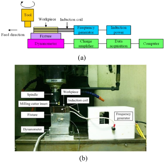
The experimental set-up for thermal-assisted milling of SKD11 steel is shown in
Fig. 1. Experiments were conducted on an MC500 milling machine without any lubricant or cooling. A cutting tool (APKT 1604PDR-GM, PRAMET, Czech Republic) with carbide inserts of diameter 40 mm was used. Induction temperature was created using 84 kHz of high-frequency power generated by magnetic induction heating equipment: induction power and frequency generator.
Fig. 1Experimental set-up (a) Schematic diagram and (b) experimental photograph

In this study, after each cutting experiment, the carbide inserts were replaced by new ones to avoid the influence of tool wear on the experimental results.
The cutting force was monitored by a piezoelectric force dynamometer (Kistler 9257B), which can measure three orthogonal cutting force components (Fx, Fy, and Fz). The dynamometer is connected to a charge amplifier for amplifying the output voltages, which are proportional to the measuring forces. Subsequently, an acquisition system with DASYlab 10.0 software is used to save the data on a computer.
2.3. Magnetic Induction Heating Process
In the magnetic induction heating process, induction heat is generated by modifying the induction current within the workpiece. Alternating current is applied to the coil to generate induction current within the workpiece. The intensity of the current is determined by the magnetic flux depending on the permeability (conductivity of the magnetic field) and resistivity of the material (electrical resistance of the electric current).
In general, a transient (time-dependent) heat transfer process in a metal workpiece can be described by the Fourier equation given as
Eq. (1).
where T, ρ, c, and k are the temperature (oC), density (g/cm3), specific heat (J/(kg.K)), and thermal conductivity of the material (W/(m.K)), respectively, and Q is the heat source density induced by the eddy currents per unit time on a unit volume. This heat source is determined by solving electromagnetic problems.
In most cases of TAM by induction heating, boundary conditions are heat losses due to radiation and convection. Hence, the boundary condition is expressed as
Eq. (2).
where ∂T/∂n is the temperature gradient in a direction normal to the surface at the point under consideration; α, CS, and QS correspond to the convection surface heat transfer coefficient, radiation heat loss coefficient, and surface loss; and n is the boundary surface symbol.
Eq. (3) with boundary conditions (
Eq. (2)) represents the mathematical model of the heat transfer process in magnetic induction heating and heat transfer applications.
Lei Zhang
14 applied the heat transfer equation to simulate the heat transfer process during magnetic induction heating using COMSOL finite element software. The effect of different parameters on the heat transfer process was also investigated.
In this study, the workpiece temperature is controlled by a hand-held digital contact thermometer (model 3527A from TSURUGA, Japan). The thermometer uses K type thermocouples with a temperature range of −99 to 1299oC. The frequency of results displayed is 2 s−1. In the range of 0 to 400oC, the error of the device is ± (0.2% RDG + 0.5oC).
2.4 Chip Shrinkage Coefficient Determination
The change in the thickness of the uncut chip due to plastic deformation is evaluated by the chip shrinkage coefficient (K), which depends on all the factors that affect the chip deformation: mechanical properties of the workpiece, geometry of the cutting tool, machining parameters, and other cutting conditions. If the volume of the metal block before and after deformation is constant, the chip width when the angle λ is small (λ < 30
o) varies insignificantly compared to the cut width. K is determined by
Eq. (4).
7
where L and Lf are the uncut chip and the actual chip length, respectively. Because of the difficulty in the determination of uncut chip length, the method of weight measurement is usually used as follows:
The cutting area is:
where Q and ρ are the mass of the chip (g) and destiny of the workpiece material (g/cm3), respectively.
Because the volume of the chip is constant, we have
where fr and t are the feed rate (mm/rev) and cutting depth (mm), respectively.
By substituting
Eqs. (6) in
(4), K is determined as follows:
By substituting
Eqs. (5) in
(7), K is determined as follows:
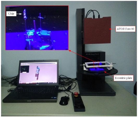
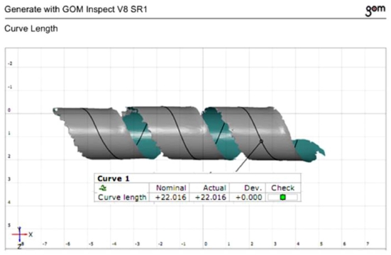
In this study, chip length was measured using a 3D scanning method incorporating GOM Inspect Professional 3D data analysis software for high accuracy. The chips were scanned by ATOS Core 80 3D scanners on an ATOS ScanPort system (
Fig. 2). This is an automated system that measures and tests small details with six kinematics combined movement around work points. The three motorized axes are the tilting, rotation, and linear axes. The three manual axes are an eccentric plate (eccentric adjustment with two degrees of freedom), a sensor axis (stepless rotation around sensor axis 0-90
°), and an adapter for height variation. ATOS Core 80 uses blue light technology, which provides high accuracy, and the scan results are not affected by ambient light owing to different light frequencies. Subsequently, GOM Inspect 3D data analysis software is used to analyze the data and measure the chip length as shown in
Fig. 3.
Fig. 2The ATOS scan port system

Fig. 3Result of chip length measurement
3. Results and Discussions
3.1 Chip Morphology
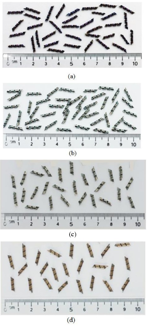
Figs. 4(a)-
4(d) show the chip morphology of the milling of SKD11 steel with machining parameters (V = 235 m/min, f = 305 mm/min, and t = 1.5 mm) at room temperature and 200, 300, and 400
oC, respectively. Continuous chips are formed by the plasticity characteristics of the workpiece material. However, a chip’s color is completely different in traditional machining than that in TAM. In traditional machining, a chip’s color is dark purple due to the heat generated and transferred from the heating sources to the chip. However, in TAM, the color of a chip is much brighter because the cutting temperature was pre-elevated, thereby causing more uniform heat transfers to the chip.
Fig. 4Chip morphology during conventional machining (a) and TAM at 200oC (b), 300oC (c), and 400oC (d)
3.2 Effect of Heating Process on Cutting Force and Chip Shrinkage Coefficient
Fig. 5 shows the experimental results of the dependence of cutting force on the cutting speed at elevated temperatures.
Table 2 presents the cutting force and chip shrinkage coefficient values at various cutting speeds and temperatures. The results show that the cutting force reduces remarkably during TAM at 200
oC compared to that during conventional machining. The cutting force reduces when the temperature is increased to 300 and 400
oC. ΔF is the percentage of cutting force reduction determined using
Eq. (9). The maximum ΔF is 65.1% during TAM at 400
oC and a 235 m/min of cutting speed (V). Hence, higher the temperature (T), lower is the cutting force (F). The strength and hardness of a material reduce because of the effect of elevated temperatures during heating. The bonding force between metal atoms becomes weak, thereby making the cutting process easy. The main reason is the softening effect caused by heating the workpiece material during the machining process. In general, the temperature of the primary shear zone increases when (V) increases. Hence, (F) is reduced by decreasing the flow stress in the primary shear zone. Besides, when (V) increases, the contact area between the rake surface of a tool and chip is reduced leading to decreasing frictional force.
Fig. 5The cutting force depends on cutting speed (V) and temperature (T)
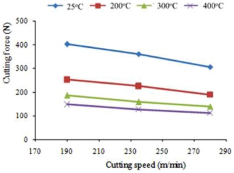
Table 2The cutting force and chip shrinkage coefficient are during machining at various cutting speeds and temperatures
Table 2
|
V (m/min) |
F (N) |
|
T= 25oC |
T= 200oC |
T= 300oC |
T= 400oC |
|
190 |
405.6342 |
250.9870 |
184.7650 |
142.7787 |
|
235 |
360.1700 |
224.9620 |
159.6134 |
125.7869 |
|
280 |
298.8975 |
189.8791 |
135.5634 |
110.9098 |
|
V (m/min) |
K |
|
T= 25oC |
T= 200oC |
T= 300oC |
T= 400oC |
|
190 |
1.2045 |
1.4985 |
1.5234 |
1.6324 |
|
235 |
1.1325 |
1.4451 |
1.5456 |
1.6587 |
|
280 |
1.0721 |
1.4236 |
1.4876 |
1.5234 |
where YT and YR are the cutting force or chip shrinkage coefficient during TAM and conventional machining, respectively.
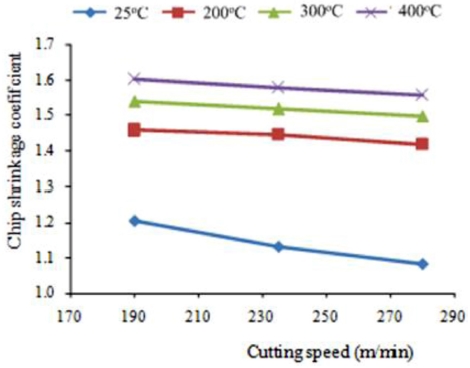
Fig. 6 presents the effect of cutting speed (V) and elevated temperature (T) on the chip shrinkage coefficient. The effect of (V) on the chip shrinkage coefficient is the same as that on the cutting force; thus, the chip shrinkage coefficient decreases when (V) increases. On the other hand, when temperature increases, the chip shrinkage coefficient also increases. The increase in the chip shrinkage coefficient (ΔK) is determined using
Eq. (9). The results show that the maximum ΔK is 31.7% during TAM at 400
oC and the cutting speed of 235 m/min. Because the material is softened under the influence of elevated temperature, the bonding between atoms becomes weak; thus, the arrangement of the metal lattice can be destroyed easily. Hence, a workpiece material will be easily deformed if the chip shrinkage coefficient is high.
Fig. 6The chip shrinkage coefficient depends on cutting speed (V) and temperature (T)
3.3 Optimization of Cutting Parameters
In this study, cutting parameters such as cutting speed (V), feed rate (f), cutting depth (t), and elevated temperature (T) are selected. Their optimal values (V, f, t, and T) will be chosen for the objective function of cutting force and chip shrinkage coefficient. Besides, the contribution percentage of the parameters will be assessed by the ANOVA method.
Taguchi proposed the signal to noise (S/N) ratio as the representative value to choose level, which is the best noise control. The S/N ratio considers both the mean and variation depending on the behavior of the target. The simplest form of the S/N ratio is the ratio of the mean (signal) to the standard deviation (noise). Because the optimization study for the objective function is the cutting force and chip shrinkage coefficient, the S/N ratio with smaller is better criteria is chosen. The formula for calculating the S/N ratio is given in
Eq. (10)15:
where n is the number of repeated experiments and ∑i=1nyi2 is the sum of the square of all the results for each experiment.
Table 3 presents the parameters with their corresponding levels. The three selected parameters (V, f, and t) combined with the heating temperature contributed to the greatest effect on the cutting process.
Table 4 shows the orthogonal array L9 according to the Taguchi method. The experimental results of the cutting force and chip shrinkage coefficient with the S/N ratio of each corresponding experiment are calculated using
Eq. (10) and shown in
Table 5. ANOVA result for the cutting force (F) is presented in
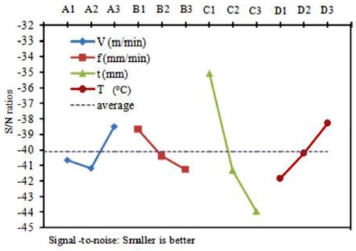
Table 6. As observed, the percentage contribution of the cutting depth (t) is the highest at 67%, while that of the supported temperature (T) and feed rate (f) are lower at 13.6 and 12.2%, respectively. The cutting speed (V) has a negligible effect on the cutting force with a contribution percentage of 7.2%.
Fig. 7 shows the S/N ratio response. The optimal conditions for F are A3B1C1D3 with V = 280 m/min, f = 230 mm/min, t = 0.5 mm, and T = 400
oC.
Table 3Parameters with levels
Table 3
|
Symbol |
Control parameter |
Unit |
Level |
|
1 |
2 |
3 |
|
A |
Cutting speed (V) |
m/min |
190 |
235 |
280 |
|
B |
Feed rate (f) |
mm/min |
230 |
305 |
380 |
|
C |
Cutting depth (t) |
mm |
0.5 |
1 |
1.5 |
|
D |
Temperature (T) |
oC |
200 |
300 |
400 |
Table 4The orthogonal array L9.
Table 4
|
Trial No. |
V
(m/min) |
f
(mm/min) |
t
(mm) |
T
(oC) |
|
1 |
190 |
230 |
0.5 |
200 |
|
2 |
190 |
305 |
1 |
300 |
|
3 |
190 |
380 |
1.5 |
400 |
|
4 |
235 |
230 |
1 |
400 |
|
5 |
235 |
305 |
1.5 |
200 |
|
6 |
235 |
380 |
0.5 |
300 |
|
7 |
280 |
230 |
1.5 |
300 |
|
8 |
280 |
305 |
0.5 |
400 |
|
9 |
280 |
380 |
1 |
200 |
Table 5The observed values are calculated
Table 5
|
Trial No. |
Cutting force |
Chip shrinkage coefficient |
|
F |
X(F) |
K |
X(K) |
|
1 |
62.205 |
-35.8765 |
1.6539 |
-4.37032 |
|
2 |
129.917 |
-42.2733 |
1.6056 |
-4.11278 |
|
3 |
155.140 |
-43.8145 |
1.4328 |
-3.12343 |
|
4 |
90.248 |
-39.1087 |
1.7531 |
-4.87623 |
|
5 |
224.962 |
-47.0422 |
1.4451 |
-3.19792 |
|
6 |
74.014 |
-37.3862 |
1.2253 |
-1.7651 |
|
7 |
112.068 |
-40.9897 |
1.7013 |
-4.61541 |
|
8 |
39.256 |
-31.8781 |
1.6314 |
-4.25132 |
|
9 |
134.258 |
-42.5588 |
1.2802 |
-2.14575 |
Table 6Results of ANOVA for F
Table 6
|
Factor |
Mean S/N ratio of each level |
The total
squared |
Contribution |
|
1 |
2 |
3 |
|
A |
-40.65 |
-41.18 |
-38.48*
|
1812 |
0.072 |
|
B |
-38.66*
|
-40.40 |
-41.25 |
3058 |
0.122 |
|
C |
-35.05*
|
-41.31 |
-43.95 |
16810 |
0.670 |
|
D |
-41.83 |
-40.22 |
-38.27*
|
3423 |
0.136 |
Fig. 7Mean of S/N ratios of the factors considering F

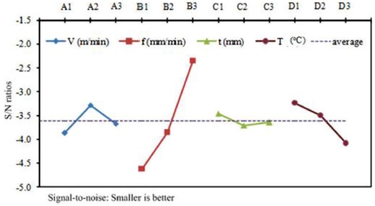
Table 7 presents the ANOVA result for the chip shrinkage coefficient (K). The results show that the percentage contribution of the feed rate (f) was the highest at 82.7%, while that of the supported temperature (T) and cutting speed (V) are lower at 11.7 and 4.6%, respectively. The cutting depth (t) has negligible effect on the chip shrinkage coefficient with a contribution percentage of 1.1%. The S/N ratio response is shown in
Fig. 8. The optimal conditions for K are A2B3C1D1 with V = 235 m/min, f = 380 mm/min, t = 0.5 mm, and T = 200
oC.
Table 7Results of ANOVA for chip shrinkage coefficient (K)
Table 7
|
Factor |
Mean S/N ratio of each level |
The total
squared |
Contribution |
|
1 |
2 |
3 |
|
|
|
A |
-3.869 |
-3.288*
|
-3.671 |
0.013 |
0.046 |
|
B |
-4.621 |
-3.854 |
-2.345*
|
0.234 |
0.827 |
|
C |
-3.462 |
-3.712 |
-3.646*
|
0.003 |
0.011 |
|
D |
-3.238*
|
-3.498 |
-4.084 |
0.033 |
0.117 |
Fig. 8Mean of S/N ratios of the factors considering K
3.4 The Cutting Force and the Chip Shrinkage Coefficient Models
The cutting force and chip shrinkage coefficient models depend on the technological parameters (V, f, and t) and supported temperature for the machining process (T) and are described by
Eqs. (11) and
(12), respectively.
where a
1 and a
2 are coefficients; b
1, c
1, d
1, e
1 and b
2, c
2, d
2, e
2 are the exponents determined from the experiments; and F is the synthetic cutting force analyzed by the three cutting force components (Fx, Fy, and Fz) according to
Eq. (13).
In this study, the Gauss–Newton method is used to construct a nonlinear regression function of the cutting force and chip shrinkage coefficient models. This method is applied in the nonlinear regression tool of Minitab 17 software. The results of cutting force and chip shrinkage coefficient presented in
Tables 4 and
5, respectively, obtained from the experiments and the orthogonal array L9 are used as input data for the method. The values of the coefficients and exponents are listed in
Table 8.
Table 8The coefficients and exponents of the cutting force and chip shrinkage coefficient model
Table 8
|
Coefficient |
a1
|
b1
|
c1
|
d1
|
e1
|
|
Value |
36235.7 |
-0.737867 |
0.453832 |
0.964106 |
-0.770712 |
|
Coefficient |
a2
|
b2
|
c2
|
d2
|
e2
|
|
Value |
16.9238 |
-0.071819 |
-0.489535 |
0.011429 |
0.135969 |
The nonlinear regression functions of the cutting force and chip shrinkage coefficient during the TAM of SKD11 steel are given by
Eqs. (14) and
(15), respectively.
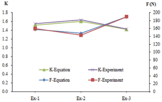
To evaluate the accuracy of the cutting force and chip shrinkage coefficient models, extra experimental data was used as shown in
Fig. 9, where: experiment 1, 2, 3 (Ex-1, Ex-2, Ex-3) were performed at the fixed feed rate of 305 mm/min and the fixed cutting depth of 1.5 mm while the cutting speed and elevated temperature were corresponding at (235 m/min, 300
oC), (190 m/min, 400
oC) and (280 m/min, 200
oC), respectively. The results show that the graph, which is built using the experimental data, is similar to the one built using the numerical data. Hence, the cutting force and chip shrinkage coefficient models represented by
Eqs. (14) and
(15), respectively, have high accuracy.
Fig. 9Comparing the experimental and numerical of the cutting force and the chip shrinkage coefficient value
By using
Eqs. (14) and
(15) and the Maple software tool,
Figs. 10 and
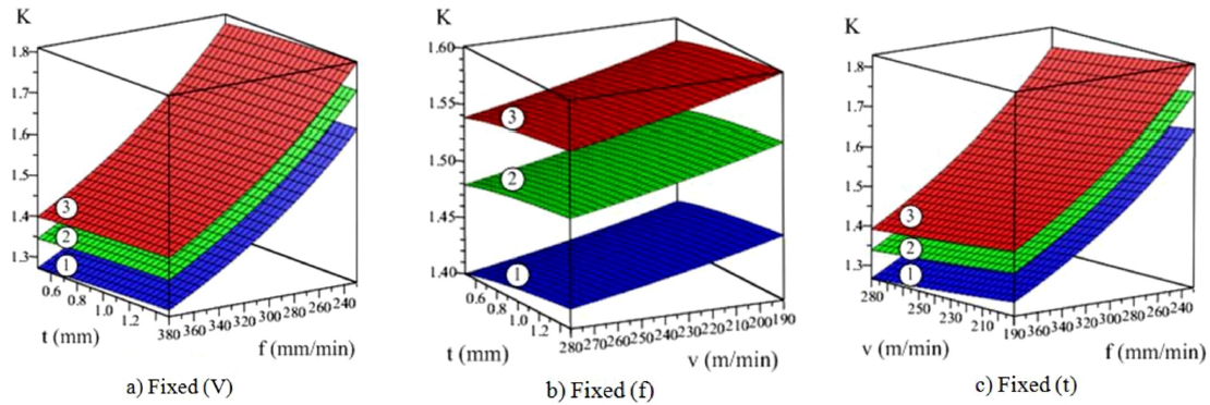
11 were also built to present the relationship between the cutting force/chip shrinkage coefficient and the machining parameters at elevated temperatures.
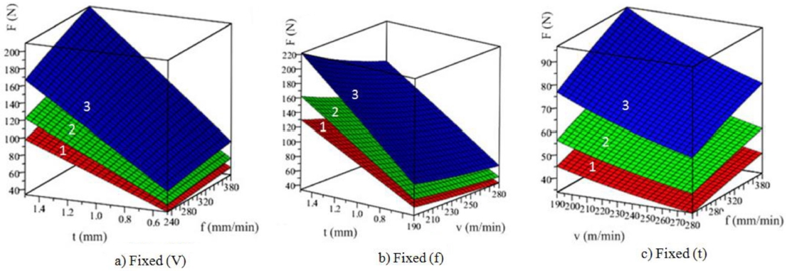
Fig. 10 shows that when the temperature for the machining process is high, the cutting force is low.
Figs. 10(a)-
10(c) show the cutting force at fixed (V), (f) and (t), respectively, and the slope of the cutting force graph is maximum when changing (t). Hence, cutting depth has the greatest effect on the cutting force.
Fig. 10(c) shows the slope of the cutting force graph when the change in (V) is higher than that in (f). This means that the contribution percentage of (V) is higher than that of (f) on the cutting force (F).
Fig. 10The relationship between the cutting force (F) and technological parameters (The graphs are labeled 1, 2, 3 in order of roughness graph at 200oC, 300oC, and 400oC)

Fig. 11The relationship between chip shrinkage coefficient (K) and machining parameters (The graphs are labeled 1, 2, 3 in order of roughness graph at 200oC, 300oC, and 400oC)

Fig. 11 presents the relationship between the chip shrinkage coefficient (K) and machining parameters and shows that high temperatures lead to large chip shrinkage coefficient values.
Figs. 11(a) and
11(c) are graphs of the chip shrinkage coefficient at fixed (V) and (t), respectively, indicating the increasing chip shrinkage coefficient with changing (f). Thus, (f) makes a major contribution to (K).
Fig. 11(c) is the chip shrinkage coefficient graph at a fixed (f) showing that (f) and (t) have negligible influence on K.
4. Conclusions
A study on the cutting force and chip shrinkage coefficient during the TAM by induction heating of tool steel SKD11 is presented in this study. By heating the workpiece before machining, the cutting force reduced and the chip shrinkage coefficient increased because of the softened material. The level of effect of each parameter and the optimal conditions for the cutting force and chip shrinkage coefficient were determined. The equations of the cutting force and chip shrinkage coefficient, which depend on the cutting parameters and elevated temperature, were established and they showed good agreement with the experimental data.
ACKNOWLEDGMENTS
This paper was presented at PRESM 2019
REFERENCES
- 1.
Benga, G. C. and Abrao, A. M., “Turning of Hardened 100CR6 Bearing Steel with Ceramic and PCBN Cutting Tools,” Journal of Materials Processing Technology, Vols. 143-144, pp. 237-241, 2003.
10.1016/S0924-0136(03)00346-7
- 2.
Chinchanikar, S. and Choudhury, S. K., “Effect of Work Material Hardness and Cutting Parameters on Performance of Coated Carbide Tool when Turning Hardened Steel: An Optimization Approach,” Measurement, Vol. 46, No. 4, pp. 1572-1584, 2013.
10.1016/j.measurement.2012.11.032
- 3.
Brecher, C., Emonts, M., Rosen, C.-J., and Hermani, J.-P., “Laser-Assisted Milling of Advanced Materials,” Physics Procedia, Vol. 12, pp. 599-606, 2011.
10.1016/j.phpro.2011.03.076
- 4.
Baili, M., Wagner, V., Dessein, G., Sallaberry, J., and Lallement, D., “An Experimental Investigation of Hot Machining with Induction to Improve Ti-5553 Machinability,” Applied Mechanics and Materials, Vol. 62, pp. 67-76, 2011.
10.4028/www.scientific.net/AMM.62.67
- 5.
Ginta, T. L. and Amin, A. N., “Thermally-Assisted End Milling of Titanium Alloy Ti-6Al-4V Using Induction Heating,” International Journal of Machining and Machinability of Materials, Vol. 14, No. 2, pp. 194-212, 2013.
10.1504/IJMMM.2013.055737
- 6.
Sun, S., Brandt, M., and Dargusch, M., “The Effect of a Laser Beam on Chip Formation During Machining of Ti-6Al-4V Alloy,” Metallurgical and Materials Transactions A, Vol. 41, No. 6, pp. 1573-1581, 2010.
10.1007/s11661-010-0187-5
- 7.
Pham, T.-H., Mac, T.-B., Tong, V.-C., Banh, T.-L., and Nguyen, D.-T., “A Study on the Cutting Force and Chip Shrinkage Coefficient in High-Speed Milling of A6061 Aluminum Alloy,” The International Journal of Advanced Manufacturing Technology, Vol. 98, Nos. 1-4, pp. 177-188, 2018.
10.1007/s00170-017-1063-x
- 8.
Pham, T.-H., Mac, T.-B., Tong, V.-C., Banh, T.-L., and Nguyen, D.-T., “Simulation and Experimental Studies to Verify the Effect of Cutting Parameters on Chip Shrinkage Coefficient and Cutting Forces in Machining of A6061 Aluminum Alloy,” Advances in Mechanical Engineering, Vol. 8, No. 10, 2016.
10.1177/1687814016673297
- 9.
Mac, T.-B., Dinh, V.-C., Banh, T.-L., and Nguyen, D.-T., “Cutting Force Model for Thermal-Assisted Machining of Tool Steel based on the Taguchi Method,” Metals, Vol. 8, No. 12, Paper No. 992, 2018.
10.3390/met8120992
- 10.
Hasçalık, A. and Çaydaş, U., “Optimization of Turning Parameters for Surface Roughness and Tool Life based on the Taguchi Method,” The International Journal of Advanced Manufacturing Technology, Vol. 38, Nos. 9-10, pp. 896-903, 2008.
10.1007/s00170-007-1147-0
- 11.
Mukherjee, I. and Ray, P. K., “A Review of Optimization Techniques in Metal Cutting Processes,” Computers & Industrial Engineering, Vol. 50, Nos. 1-2, pp. 15-34, 2006.
10.1016/j.cie.2005.10.001
- 12.
Wang, C., Xie, Y., Zheng, L., Qin, Z., Tang, D., et al., “Research on the Chip Formation Mechanism during the High-Speed Milling of Hardened Steel,” International Journal of Machine Tools and Manufacture, Vol. 79, pp. 31-48, 2014.
10.1016/j.ijmachtools.2014.01.002
- 13.
Zhang, L., “Numerical Modeling of Induction Assisted Subsurface Heating Technology,” Ph.D. Thesis, Worcester Polytechnic Institute, 2012.
- 14.
Roy, R. K., “A Primer on the Taguchi Method,” Van Nostrand Reinhold, New York, 1990.
Biography
- Thi-Bich Mac
Ph.D candidate in the School of Mechanical Engineering, Hanoi University of Science and Technology, Vietnam. Her research interests are CAD/CAM/CAE, forming and Machining process.
- Tien-Long Banh
Professor in the School of Mechanical Engineering, Hanoi University of Science and Technology, Vietnam. His research interests are Metal cutting, industrial instrument, CAD/CAM/CAE
- Duc-Toan Nguyen
Associate Professor in the School of Mechanical Engineering, Hanoi University of Science and Technology, Vietnam. His research interests are Plasticity, Machining Process, CAD/CAM/CAE.