ABSTRACT
Since sCO2 (Supercritical Carbon Dioxide) turbomachinery are generally small and operate at high rotational speed, the bearings remain a significant challenge to the design of the turbomachinery for the sCO2 power cycles. However, a fluid induced instability similar to the oil whirl may occur even with the magnetic bearing under high pressure and high speed conditions of the sCO2 turbomachinery. This paper presents experimental investigation on the instability of a sCO2 compressor supported by the magnetic bearing. First, we introduce the sCO2 compressor supported by the magnetic bearing. The procedure to guarantee the rotordynamic performance of the sCO2 compressor supported by the magnetic bearing is provided. Then, the effects of the working condition such as the pressure and rotating speed on the fluid induced instability are investigated experimentally. Finally, a strategy to resolve the fluid-induced instability with conventional PID control is proposed and experimentally verified.
-
KEYWORDS: sCO2 Turbomachinery, Magnetic bearing, Instability
-
KEYWORDS: 초임계 이산화탄소 터보 압축기, 자기 베어링, 불안정성
1. Introduction
The sCO
2 power cycles provide highly efficient, highly dense and less corrosive power generation compared with other cycle (Incumbent Steam Rankine or Air Brayton Cycles) over a wide range of applications such as waste heat recovery, concentrating solar power, nuclear, and fossil energy.
1,2 Efficiency and power density in power conversion systems are the key criteria according to increasing energy demands over the world. In addition, corrosiveness is also significant issues for turbines and compressors in most power cycles.
Since the sCO
2 turbomachinery are generally small and operate at high rotational speeds, bearings pose a significant challenge to the design of turbo-compressors/expanders for sCO
2 power cycles.
2 Although the basic sCO
2 cycle consists of a compressor, turbine, heater and cooler as well as a recuperator, efficient, reliable and compact turbine and compressor for high-pressure environment are most significant components to realize robust operation and high-efficiency.
1
Magnetic bearings present several advantages over pure mechanical bearings such as rolling element bearing, hydrostatic/dynamic bearing, and gas foil bearing although bearing selection is rather complex and depends on many factors such as cost, duty cycle, load, speed, size/weight, efficiency, and dynamic performance.
3-6 For examples, a wide range of operating conditions, controllable bearing dynamics, and measurement of bearing forces are the well-known strong point of magnetic bearings. In addition, magnetic bearing technology has been gaining more and more area in turbomachinery and rotating equipment for couple of decades together with remarkable development and progress of integrated power electronics and semiconductor industries.
7
Although journal bearing may have instability known as oil whirl and whip, fluid induced instability like oil whirl may also happen even with magnetic bearing under both high pressure and speed conditions of sCO
2 turbomachinery.
8 Dedicate analysis was required to evaluate instability of journal bearing with sCO
2 since the supercritical fluids are generally 100 to 1,000 times denser than gases and slightly lighter than liquids.
9 In addition, experimental investigation of rotordynamic performance is very important for designing critical components of turbomachinery such as rotor, bearing, seal and so on.
10 However, there are few studies and practical guidelines on sCO
2 turbomachinery supported by magnetic bearings.
With magnetic bearing, vibration or instability of journal bearing can be reduced as well as the working condition of the rotating machinery can be extended or optimized.
11-13 Adding damping, coupled stiffness or preload with magnetic bearing may improve the rotordynamic stability.
14,15 In addition, the proper control of magnetic bearing enhances the rotordynamic performance.
16
This paper presents experimental investigation on instability of a sCO2 compressor supported by magnetic bearing. First, we introduce the sCO2 compressor supported by magnetic bearing. Procedure to guarantee rotordynamic performance of the sCO2 compressor supported by magnetic bearing is provided. Then, effects of working condition such as pressure and rotating speed on the fluid induced instability are investigated experimentally. Finally, a strategy to resolve the fluid-induced instability with conventional PID control are proposed and experimentally verified.
2. sCO2 Compressor Supported by Magnetic Bearing
2.1 Specifications
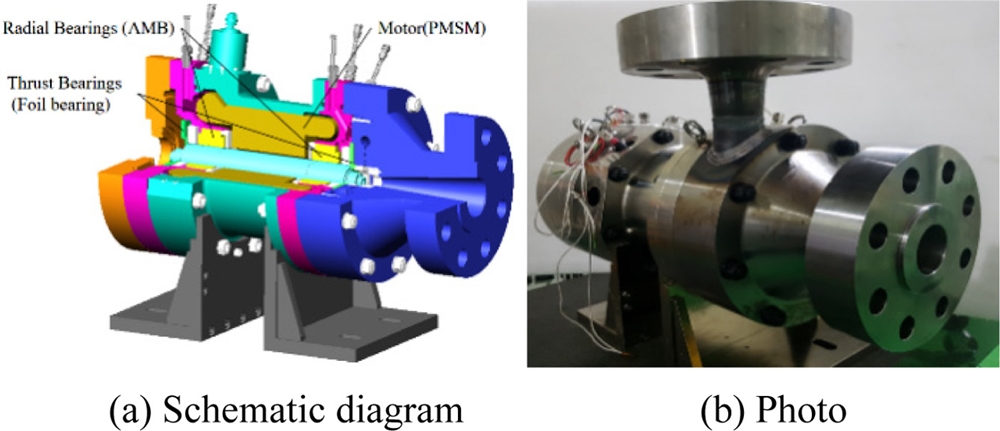
The test rig for a sCO
2 compressor supported by magnetic bearing is shown in
Fig. 1. Specifications of the compressor are summarized in
Table 1.
Fig. 1sCO2 Compressor supported by magnetic bearings

Table 1Specifications of sCO2 compressor supported by magnetic bearings
Table 1
|
Item |
Value |
Unit |
Consideration |
|
Rated speed |
36,000 |
rpm |
|
|
Power |
60 |
kW |
|
|
Separation margin |
20 |
% |
API617 |
|
Max vibration |
0.045 |
mm |
ISO14893-2 Zone A/B |
|
Radial bearing |
Magnetic bearing |
|
|
|
Thrust bearing |
Gas foil bearing |
|
|
2.2 Rotor Bearing System
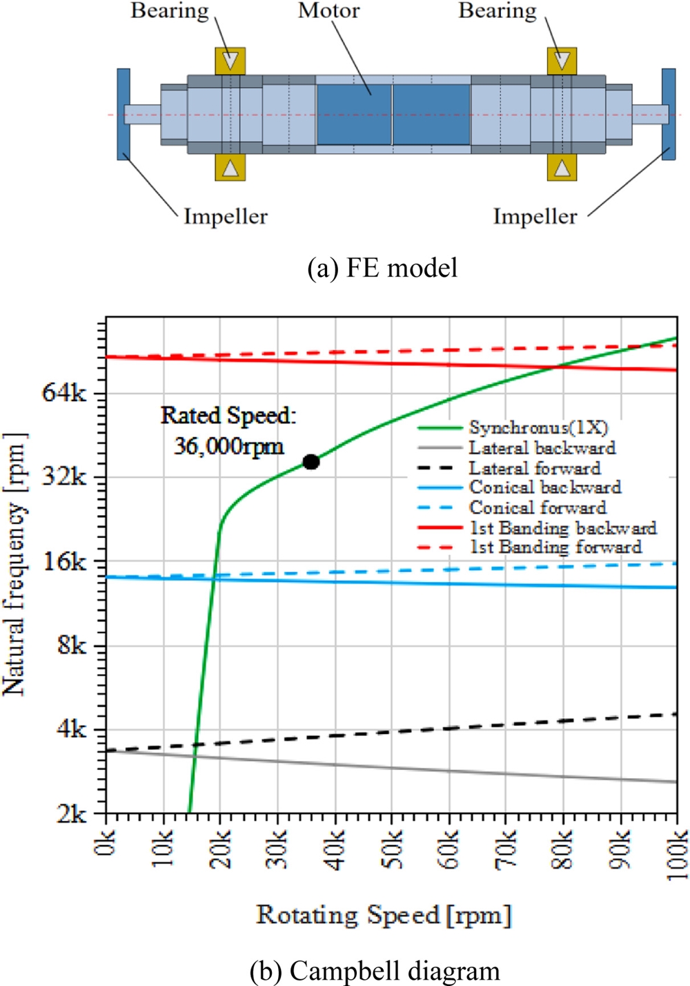
The 60 kW turbo-compressor is composed of one shaft with a built-in motor and two impellers, two radial magnetic bearings and thrust foil bearings. A PMSM (Permanent Magnet Surface Mount) motor with two poles is used to drive the compressor. The rotor bearing system of the compressor is designed to have symmetric shape and to satisfy the separation margin of the API 617. Finite element modeling is used to analyze the lateral vibrations considering the gyro and shear effects, as shown in
Fig. 2.
17 The model is composed of 20 beam elements and totally has 84 DOF (Degrees of Freedom). Campbell diagram of the rotor bearing system is shown in
Fig. 2(b) and the shaft has enough speed margin from the 1st bending mode (79,091 rpm).
Fig. 2FE model and critical speed analysis
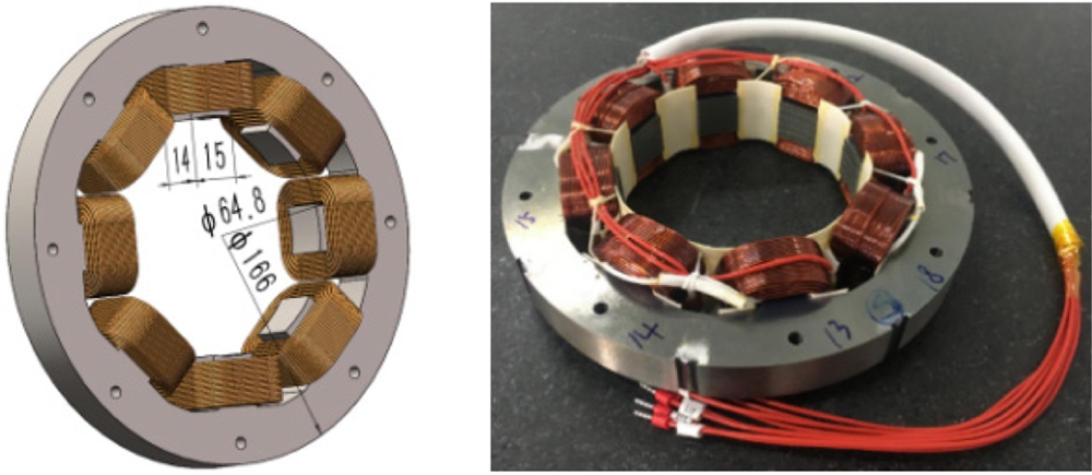
Radial magnetic bearing is designed considering G2.0 balancing grade and safety factor, and its geometric specifications are summarized in
Table 2. The safety factor for load capacity of the radial magnetic bearing is determined considering the effect of fluid dynamic forces. The required static load to support the rotor is 46 N, while the dynamic load due to the rotor unbalance is 35 N. However, the load capacity of the radial magnetic bearing is determined as 186 N considering the safety factor 4. The designed heteropolar radial magnetic bearing is shown in
Fig. 3.
Table 2Specifications of radial magnetic bearing
Table 2
|
Item |
Value [mm] |
|
Rotor diameter |
64 |
|
Magnetic bearing clearance |
0.4 |
|
Back-Up bearing clearance |
0.2 |
Fig. 3Radial magnetic bearing
An inductive displacement sensor is used to control the magnetic bearings and its transducer is integrated into the magnetic bearing controller. Sine wave with 20 kHz drives the sensing coil and the current flowing through the coil is measured to calculate the inductance of the sensing coil. The sensors are mounted differentially on both side of the object and the displacement of the object is obtained from the inductance difference between the two sensors. The measuring range is ±500 μm in radial direction and ±1,000 μm in axial direction. The current control is a simple PI controller, while the displacement control is a PID controller with some filters. In addition, an imbalance controller is used to reduce the synchronous vibration of the rotor. Specifications of the controller are summarized in
Table 3.
Table 3Specification of magnetic bearing controller
Table 3
|
Item |
Specification |
|
Inductive displacement sensors |
6 units (4 for radial, 2 for thrust) |
|
Displacement controller |
5 axis (4 for radial, 1 for thrust) |
|
Current controller |
10 axis (8 for radial, 2 for thrust) |
|
Control frequency [kHz] |
10 |
|
Current control bandwidth [kHz] |
500 |
3. Fluid Induced Instability
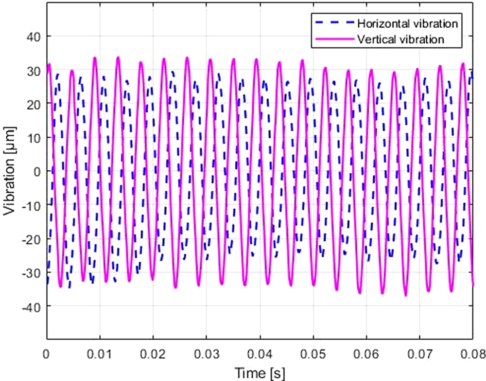
3.1 Response under Atmospheric Pressure
Simple unbalance test is performed under atmospheric pressure and the vibrations near first resonance (15,000 rpm) is shown in
Fig. 4. With proper PID gains, the magnitude of the unbalance response is less than 0.035 mm, which is satisfied with ISO14893-2 zone A/B.
Fig. 4Vibrations at 15,000 rpm under atmospheric pressure

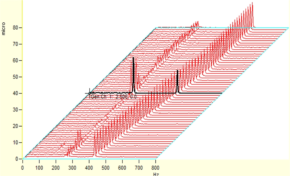
3.2 Responses under the Pressurized sCO2
The waterfall chart of the rotor vibration from 24,000 to 36,000 rpm under 10 bar of sCO
2 are shown in
Fig. 5. Not only dominant synchronous component but also sub-harmonic one appear at 270 Hz. The frequency of the sub-harmonic component is close to half of the synchronous one and coincides with the first resonance frequency in
Fig. 4. In addition, not the frequency but the magnitude of the sub-harmonic component varies according to the rotating speed.
Fig. 5Waterfall chart of the rotor vibration under 10 bar

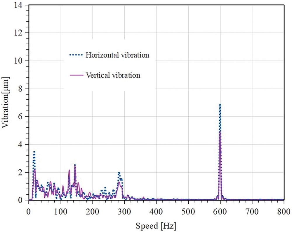
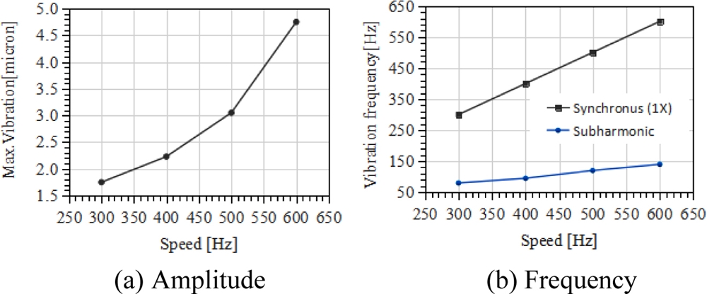
Under the pressure of 70 bar, another low-frequency subharmonic vibration appears, as shown in
Fig. 6. The frequency of this sub-harmonic vibration not only increase with the rotating speed, but also the amplitude increase with the rotating speed, as shown in
Fig. 7.
Fig. 6Frequency spectrum of the rotor vibration under high pressure (70 bar)
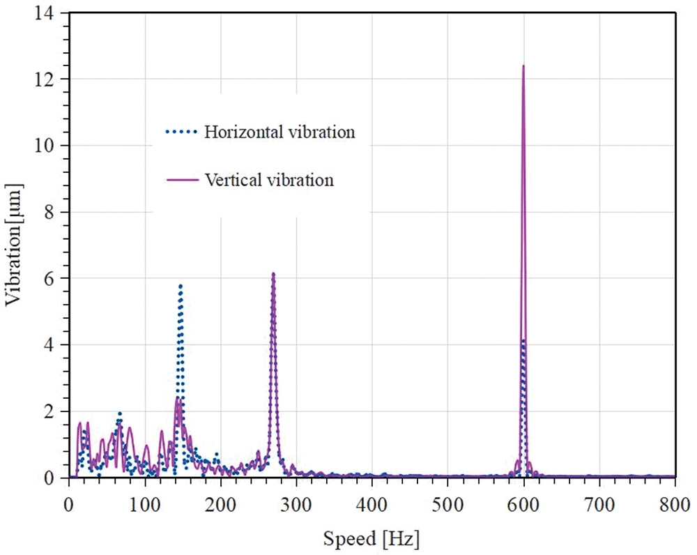
Fig. 7Sub-harmonic vibration according to rotating speed
4. Control of Fluid Induced Instability
This sub-harmonic vibration frequency, near 270 Hz, is caused by cross-couple stiffness of the pressurized sCO
2 whirling. The cross-couple stiffness of the pressurized sCO
2 whirling equivalently reduces the damping of the bearing and causes the subharmonic vibration of the system, which is the average whirling velocity of the fluid between the rotor and the bearing.
18
The damping of the sCO
2 compressor can be increased by tuning the PID control gains. After the gain is re-tuned, the vibration amplitude at 270 Hz can be reduced successfully, as shown in
Fig. 8. The proportional gain remains low for the system stability while the derivative gain increases for sub-harmonic vibration. The vibration amplitude at 140 Hz is reduced by about 56%, from 5.9 to 2.6 μm, and the vibration amplitude at 270 Hz is reduced by about 67%, from 6.2 to 2.0 μm. The amplitude of the synchronous vibration was reduced by 45% from 12.4 to 6.8 μm.
Fig. 8 Frequency spectrum of vibration under high pressure (70 bar) after re-tuning the position control gains

5. Conclusion
This paper presents experimental investigation on instability of a sCO2 compressor supported by magnetic bearings. First, we introduce the sCO2 compressor supported by magnetic bearings. Then, effects of working condition such as pressure and rotating speed on the fluid-induced instability are investigated experimentally. Finally, a strategy to resolve the fluid-induced instability with conventional PID control are proposed and experimentally verifie.
ACKNOWLEDGMENTS
This paper was supported by Korea Institute for Advancement of Technology (KIAT) grant funded by the Korea Government (MOTIE) (No. P0006915, Korea-China Joint R&D Project).
REFERENCES
- 1.
Allison, T., Wilkes, J., Brun, K., and Moore, J., “Turbomachinery Overview for Supercritical CO2 Power Cycles,” Proc. of the 46th Turbomachinery Symposium, Turbomachinery Laboratory, Texas A&M Engineering Experiment Station, pp. 147-215, 2017.
10.1016/B978-0-08-100804-1.00007-4
- 2.
Fleming, D., Holschuh, T., Conboy, T., Rochau, G., and Fuller, R., “Scaling Considerations for a Multi-Megawatt Class Supercritical CO2 Brayton Cycle and Path Forward for Commercialization,” Proc. of the Turbo Expo: Power for Land, Sea, and Air on American Society of Mechanical Engineers, pp. 953-960, 2012.
10.2172/1111079
- 3.
Brun, K., Friedman, P., and Dennis, R., “Fundamentals and Applications of Supercritical Carbon Dioxide (sCO2) Based Power Cycles,” Woodhead Publishing, 2017.
- 4.
Chapman, P., “Advanced Gas Foil Bearing Design for Supercritical CO2 Power Cycles,” Proc. of the 5th International Symposium-Supercritical CO2 Power Cycles, p. 15, 2016.
- 5.
Dimond, T., Younan, A., and Allaire, P., “Journal Bearing Lubrication Using sCO2-A Theoretical Study,” Proc. of the Supercritical CO2 Power Cycle Symposium on Rensselaer Polytechnic Institute, 2009.
- 6.
Shultz, R., Pawcatuck, C., and Narayanaswamy, A., “Magnetic Bearings for Supercritical CO2 Turbomachinery,” Proc. of the 6th International Supercritical CO2 Power Cycles Symposium Pittsburgh, 2018.
- 7.
Schweitzer, G. and Maslen, E. H., “Magnetic Bearings: Theory, Design, and Application to Rotating Machinery,” Springer Berlin, 2009.
- 8.
Kim, D., Baik, S., and Lee, J. I., “Investigation of Magnetic Journal Bearing Instability Issues in Supercritical CO2 Turbomachinery,” Proc. of the Fluids Engineering Division Summer Meeting, 2019.
10.1115/AJKFluids2019-5349
- 9.
Dousti, S. and Allaire, P., “A Compressible Hydrodynamic Analysis of Journal Bearings Lubricated with Supercritical Carbon Dioxide,” Proc. of the Supercritical CO2 Power Cycle Symposium, 2016.
- 10.
Weaver, B., Tsukuda, T., Rizvi, S. A. A., Schwartz, B., Nichols, B., et al., “Experimental Measurements of Turbomachinery Rotordynamics, Component Performance, and Dynamic Control At ROMAC-A Review,” Jounal of the Gas Turbine Society Japan, Vol. 45, No. 4, pp. 235-242, 2017.
- 11.
Kasarda, M., Mendoza, H., Kirk, R., and Wicks, A., “An Experimental Investigation of the Effect of an Active Magnetic Damper on Reducing Subsynchronous Vibrations in Rotating Machinery,” Proc. of the Turbo Expo: Power for Land, Sea, and Air, pp. 801-806, 2005.
10.1115/GT2005-68593
- 12.
El-Shafei, A. and Dimitri, A., “Controlling Journal Bearing Instability Using Active Magnetic Bearings,” Journal of Engineering for Gas Turbines and Power, Vol. 132, No. 1, Paper No. 012502, 2010.
10.1115/1.3078785
- 13.
Jang, H. D., Kim, J., Han, D. C., Jang, D. Y., and Ahn, H. J., “Improvement of High-Speed Stability of an Aerostatic Bearing-Rotor System Using an Active Magnetic Bearing,” International Journal of Precision Engineering and Manufacturing, Vol. 15, No. 12, pp. 2565-2572, 2014.
10.1007/s12541-014-0628-y
- 14.
Pham, M. N. and Ahn, H. J., “Experimental Optimization of a Hybrid Foil-Magnetic Bearing to Support a Flexible Rotor,” Mechanical Systems and Signal Processing, Vol. 46, No. 2, pp. 361-372, 2014.
10.1016/j.ymssp.2014.01.012
- 15.
Jeong, S. and Lee, Y. B., “Vibration Control of High-Speed Rotor Supported by Hybrid Foil-Magnetic Bearing with Sudden Imbalance,” Journal of Vibration and Control, Vol. 23, No. 8, pp. 1296-1308, 2017.
10.1177/1077546315592531
- 16.
Swanson, E. E., Maslen, E. H., Li, G., and Cloud, C. H., “Rotordynamic Design Audits of AMB Supported Machinery,” Proc. of the 37th Turbomachinery Symposium, pp. 133-158, 2008.
- 17.
- 18.
Krämer, E., “Dynamics of Rotors and Foundations,” Springer Science & Business Media, 2013.
Biography
- Sheng-He Jin
Master student at the Department of Software Convergence, Graduate school, Soongsil University. His research interest is magnetic bearing.
- Jae-Eun Cha
Ph.D., Senior Researcher of Fast Reactor Technology Development Division, Korea Atomic Energy Research Institute. His research interest is supercritical CO2 Power cycle technology.
- Jee-Uk Chang
Ph.D., Senior Researcher of R&D Center, IISO Inc. His research interest is Magnetic bearing control.
- Sang-Hyun Choi
Ph.D. CTO of Foshan Genesis AMB Tech Co. Ltd. His research interest is Rotor dynamics and Turbo machinery.
- Hyeong-Joon Ahn
Professor at the School of Mechanical Engineering, Soongsil University. His research interest is mechatronics including sensors, actuators and control.