ABSTRACT
This paper describes the design of a 4-axis SCARA-Type robot in the form of a scalar robot for the loading and unloading of workpieces in machine tools. The 4-axis dedicated robot is a 4-degrees-of-freedom robot consisting of a joint 1, 2, 3 motor and a 180° rotating gripper made up of a horizontal gripper and a vertical gripper. It was designed in a scalar shape that is suitable for machine tools, and the size of each link and elbow was determined through structural analysis. Through additional structural analysis, the deflection of the end center of the workpiece fixed to the horizontal gripper and the vertical gripper was designed to be within 0.1 mm, and based on the design result, a 4-axis SCARA-Type robot was manufactured, and the basic motion characteristics of the manufactured robot were tested. As a result of the characteristic test, the manufactured 4-axis SCARA-Type robot operated smoothly, so it is judged to be adequate for usage in loading and unloading the workpieces in machine tools.
-
KEYWORDS: 4-Axis scara-type robot, Machine tools, Structure analysis, Workpiece, Link, Joint
-
KEYWORDS: 4축 스카라형 로봇, 공작기계, 구조해석, 공작물, 링크, 관절
1. 서론
스마트공장(Smart Factory)에 설치된 공작기계는 자동으로 동작하여야 하고, 이를 위해서는 공작기계에 가공 전 공작물과 가공 후 공작물을 자동으로 로딩(Loading)과 언로딩(Unloading)할 수 있는 시스템이 필요하다. 이와 같은 시스템은 공작물을 이동시키는 로봇과 공작물을 적재하는 적재 장치로 구성한다. 이 시스템에 많이 사용되는 로봇은 6축 산업용 로봇과 겐츄리 로봇이다. 6축 산업용 로봇
1-8을 이용한 공작물 로딩/언로딩 시스템은 넓은 설치 면적이 필요하고, 가격이 고가인 단점이 있다. 겐츄리 로봇
9-15을 이용한 공작물 로딩/언로딩 시스템은 공작기계에 부착하는 전용 시스템과 공작기계의 상공에 설치하여 여러 대의 공작기계를 담당하는 시스템으로 구분하고, 이것들은 공작기계에 진동 등을 유발하는 문제점을 가지고 있다. 그리고 스칼라 로봇을 이용하는 방법은 로봇의 말단 부분이 공작기계의 공작물을 고정시키는 척 위치로 이동할 수 없는 단점을 가지고 있다. 따라서 공작기계에 가공 전 공작물과 가공 후 공작물을 로딩과 언로딩을 원활하게 수행할 수 있는 공작기계 전용 로봇의 개발이 필요하다.
논문에서는 공작기계에 가공 전 공작물과 가공 후 공작물을 로딩 및 언로딩을 수행할 수 있는 4축 스카라형 로봇을 설계하였다. 4축 스카라형 로봇을 구조해석을 통하여 각 링크의 크기를 결정하여 설계하였고, 설계 결과에 따라 4축 스카라형 로봇을 제작하였으며, 제작한 4축 스카라형 로봇의 기초 동작 특성 실험을 하였다.
2. 4축 스카라형 로봇의 설계
2.1 4축 스카라형 로봇의 구조
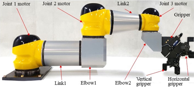
Fig. 1은 4축 스카라형 로봇의 구조를 나타내고 있고, 이것은 몸체(Body), 관절1 모터(Joint 1 Motor), 관절2 모터(Joint 2 Motor), 관절3 모터(Joint 3 Motor), 링크1(Link 1), 링크2(Link 2), 엘보우1(Elbow 1), 엘보우2(Elbow 2), 그리퍼(Gripper) 등으로 구성한다. 몸체는 관절1 모터의 하부와 고정하고, 4축 스카라형 로봇 전체가 상하로 이동되어 고정할 수 있도록 설계하였으며, 이것은 공작기계 척의 중심선과 수평 그리퍼의 중심선이 일치하도록 맞추기 위해 사용한다. 관절1 모터는 수직축을 기준으로 로봇의 전체를 회전시키고, 수직 방향 고정부는 몸체와 고정하고, 수평 고정구는 링크1과 볼트로 고정한다. 관절2 모터는 엘보우1의 상부와 고정하고, 수평 고정구는 링크2와 볼트로 고정한다. 관절3 모터는 엘보우 상부와 고정하고, 수평 고정구는 링크2와 볼트로 고정한다. 링크1은 관절1 모터와 엘보우1의 수평 방향 고정구와 연결하고, 링크2는 관절1 모터와 관절2 모터의 수평 고정구와 고정하며, 이것들은 모터와 연결되는 전선을 내부로 처리하기 위해 중공형으로 설계한다. 엘보우1은 수평 고정구와 수직 고정구는 각각 링크1과 관절2 모터와 고정하고, 이것은 “ㄱ”자 형태와 중공형으로 설계한다. 엘보우2는 수평 고정구와 수직 고정구는 각각 그리퍼와 관절3 모터의 수직 고정구와 고정하고, 이것은 “ㄱ”자 형태와 중공형으로 설계한다. 그리퍼는 수평 그리퍼와 수직 그리퍼가 180°로 구성하고 있고, 45°방향의 축을 중심으로 회전할 수 있으며, 회전하면 수평 그리퍼와 수직 그리퍼가 바뀌게 된다.
Fig. 1Structure of 4-axis SCARA-type robot
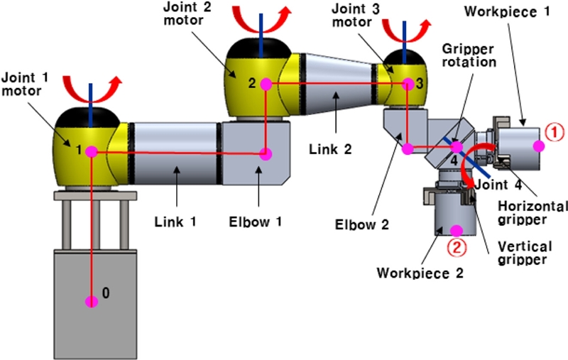
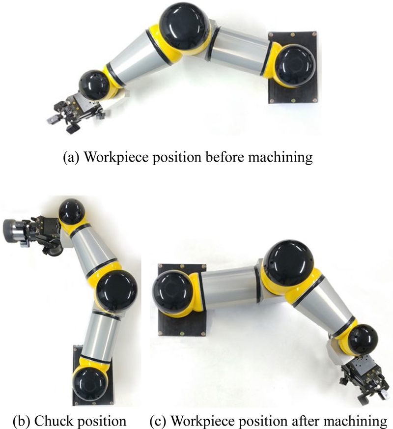
4축 스카라형 로봇은 공작기계 척의 중심선과 수평 그리퍼에 고정된 공작물의 중심선 상이 일치하도록 몸체의 상하 이동 장치를 이용하여 고정하고, 관절1 모터와 관절2 모터가 회전하여 로봇의 관절4 점이 수평 방향으로 척의 수평 중심선과 일치하도록 이동하며, 관절3 모터를 회전시켜 공작물의 중심선과 척의 수평 중심선이 일치하도록 동작한다.
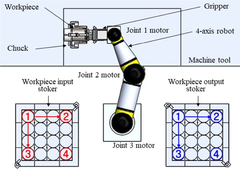
Fig. 2는 공작기계용 4축 스카라형 로봇의 사용원리를 나타내고 있고, 이것은 공작기계 평면 개략도, 4축 스카라형 로봇, 가공 전 공작물 적재 장치, 가공 후 공작물 적재 장치 등으로 구성하고 있다. 공작기계 평면 개략도는 몸체, 공작기계의 척 등이 있고, 척은 공작물을 고정하며, 공작물의 중심선이 수평을 이루도록 설계되어 있다. 4축 스카라형 로봇은 가공 전 공작물을 적재장치로부터 잡아 공작기계의 척에 로딩하며, 가공 후 공작물을 척으로부터 언로딩하여 가공 후 공작물 적재 장치에 적재한다. 가공 전 공작물 적재 장치는 가공 전에 공작물을 적재하는데 사용하고, 가공 후 공작물 적재 장치는 가공 후 공작물을 적재하는데 사용한다. 4축 스카라형 로봇이 가공 전 공작물과 가공 후 공작물을 이동시키는 순서는
Fig. 2의 화살표 방향의 순서와 같다.
Fig. 2Use principle of the 4-axis SCARA-type robot for machine tools

2.2 4축 스카라형 로봇의 구조해석
4축 스카라형 로봇을 구조해석하기 위해서 로봇의 전체 크기 및 부품의 크기를 결정해야 하고, 각 관절 모터, 그러퍼, 공작물 등을 결정해야 한다. 그리고 구조해석 시 이것들의 무게를 자중으로 적용시켜야 한다. 4축 스카라형 로봇의 크기는 공작기계에 로딩 및 언로딩 거리를 고려하여 로봇의 전체 크기인
Fig. 1에서 나타낸 점 1에서 4까지의 수평 길이가 875 mm, 점 1에서 2까지의 수평 길이가 421 mm, 점 2에서 3까지의 수평 길이가 344 mm, 점 3에서 4까지의 수평 길이가 110 mm, 점 0에서 1까지의 수직 길이가 360 mm, 점 1에서 2까지의 수직 길이가 153 mm, 점 3에서 4까지의 수직 길이가 138 mm로 결정되었다.
Table 1은 관절1-3 모터의 사양을 나타내고, 이것은 그리퍼와 공작물의 무게와 각 관절의 회전 토크를 고려하여 결정하였다. 관절1 모터와 관절2 모터는 동일한 것을 사용하였다.
Table 1The specification of joint 1-3 motors
Table 1
|
Motor |
Model |
Power
[W] |
No. of re.
[rpm] |
Reduc.
Ratio |
Torque
[Nm] |
Mass
[kg] |
|
1 |
MR32 |
0.5 |
250 |
100 : 1 |
180 |
7.3 |
|
2 |
MR32 |
0.5 |
250 |
100 : 1 |
180 |
7.3 |
|
3 |
MR20 |
0.3 |
300 |
100 : 1 |
53 |
2.7 |
그리퍼는 수평 그리퍼와 수직 그리퍼가 90°로 배치하고 있고, 45° 축을 중심으로 공기압으로 180° 회전하고, 회전하면 수평 그리퍼와 수직 그리퍼의 위치가 바뀌게 된다. 수평 그리퍼와 수직 그리퍼에는 4축 스카라형 로봇이 실제로 공작기계에서 로딩 및 언로딩할 수 있는 최대 기반 하중인 4 kg 질량의 공작물 2개를 고정하고, 공작물의 크기는 직경이 100 mm, 높이가 100 mm이다.
그리퍼의 사양은 모델 SSU25, 토크 4.6 N·m, 파지력(Gripping Forced) 953 N이다. 각각의 링크 부품과 엘보우 부품의 크기, 즉
Fig. 1에서 나타낸 부품인 링크1, 링크2, 엘보우1, 엘보우2의 크기는 구조해석을 통해 결정한다. 각 링크와 엘보우의 크기를 결정하기 위해서, 링크1 부품은 외경이 관절1 모터와 관절2 모터 수평 고정구의 직경과 동일한 146 mm, 길이가 242 mm로 결정하였다. 링크2 부품은 관절2 모터의 수평 고정구와 체결되는 외경이 142 mm이고, 관절3 모터의 수평 고정구와 체결되는 외경이 직경 92, 길이가 202 mm로 결정하였다. 엘보우1 부품은 길이가 163.5, 높이가 148, 폭이 148 mm, 그리고 엘보우2 부품은 길이가 106, 높이가 103, 폭이 138 mm로 결정하였다. 이와 같이 엘보우2의 크기를 결정한 것은 관절3 모터, 그리퍼와의 조립을 고려하였다. 링크와 엘보우 부품의 재질은 AL6061로 결정하였고, 이 재질의 인장강도는 11,003 N/cm
2(110.03 MPa)이며, 이것은 각 링크와 엘보우 부품의 응력해석 후 안전율을 평가할 때 이용한다. 각 링크와 엘보우들의 접촉 부분은 플랜지형으로 접촉 면적이 넓도록 설계하였고, 이것들은 12개의 강력 볼트로 움직이지 않도록 고정하였다.
링크1 부품, 링크2 부품, 엘보우1 부품, 엘보우2 부품의 크기인 두께를 결정하기 위해 솔리드웍스 소프트웨어를 이용하여 구조해석을 실시하였고, 구조해석 시 위에서 설명한 모든 조건을 입력하고, 모든 부품의 자중을 고려하였다. 그리고 4축 스카라형 로봇의 구조해석은
Fig. 1의 ①점과 ②점의 변위가 0.1 mm 이하가 되는 것을 목표로 하고, 이 조건이 맞을 때 구조해석 응력 결과와 각 부품 재질의 인장강도를 비교하여 안전율을 평가한다. 공작물의 중심선 끝점인 ①점과 ②점의 변위가 0.1 mm 이하가 되도록 결정한 것은 공작기계의 척과 적재 장치의 적재기구의 공차를 고려한 것이다. 구조해석 시 공작물의 중심선 끝점인 ①점과 ②점의 변위가 0.1 mm 이하가 되도록 링크1 부품, 링크2 부품, 엘보우1 부품, 엘보우2 부품의 크기인 두께를 여러번 변경하면서 수행하였다. 그 결과 링크1의 두께가 13.5 mm이고, 링크2의 두께가 20 mm, 엘보우1의 두께가 24.5 mm, 엘보우2의 두께가 24.5 mm로 결정하였다.
Fig. 3은 4축 스카라형 로봇의 구조해석 결과를 나타내고, 예상과 같이 변위와 응력이 발생하였다.
Table 2는 구조해석으로 부터 얻은 공작물의 중심선 끝점인 ①점과 ②점의 변위를 나타내고, 최대 변위는 ①점에서 -y방향으로 -0.0927 mm이고, 이것은 목표값인 0.1 mm를 만족하였다.
Fig. 3Structural analysis result of 4-axis SCARS-type robot
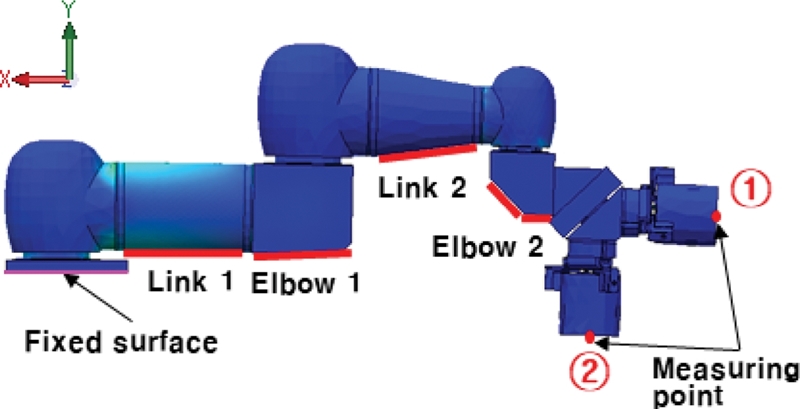
Table 2Displacement of the end points (① and ②) of the center line of the workpiece obtained from structural analysis
Table 2
|
Measuring point |
Direction |
Measured value [μm] |
|
① |
x |
2.5 |
|
y |
-92.7 |
|
z |
7.3 |
|
② |
x |
26.3 |
|
y |
-66.5 |
|
z |
0.5 |
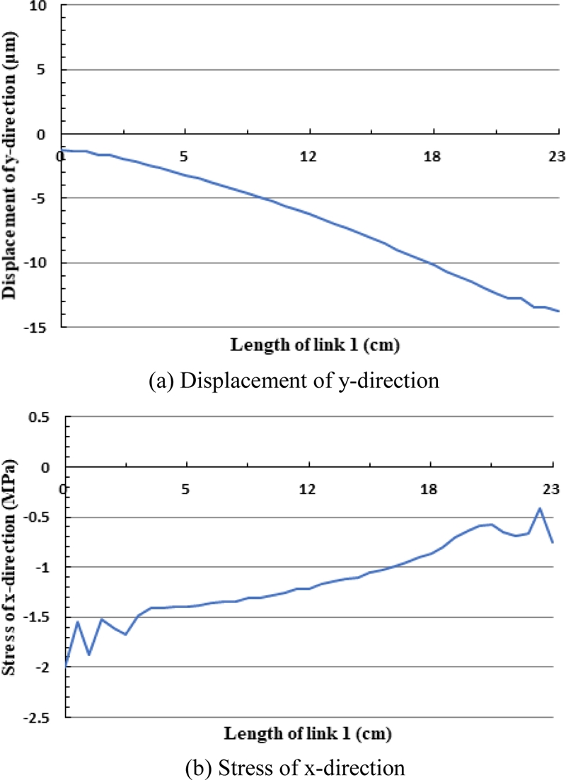
Table 3은 구조해석으로부터 얻은 링크1 부품의 변위값과 응력값을 나타내고, 이것들은 링크1 부품의 x축 선상(빨간색 표시 부분)의 값이고, 최대 변위와 응력은 각각 4.06 μm/m와 - 2.00 MPa이다. 링크1 부품은 발생된 최대 응력이 이것의 재질인 AL6061의 인장강도 110.03 MPa과 비교하여 55배 정도의 안전율을 가지고 있으므로 매우 안전하다. 이와 같이 안전율이 큰 것은 설계 시 공작물의 중심선 끝 지점의 변위를 0.1 mm 이내로 설정하였기 때문이다.
Table 3Displacement and stress of link 1 part obtained from structural analysis
Table 3
|
Direction |
Displacement
[μm] |
Stress
[MPa] |
|
Start P. |
End P. |
Min. |
Max. |
|
x |
0.29 |
4.06 |
-0.40 |
-2.01 |
|
y |
-1.23 |
-13.7 |
0.11 |
-0.72 |
|
z |
-0.02 |
0.08 |
0.05 |
-1.31 |
Fig. 4는 구조해석으로부터 얻은 링크1의 변위와 응력의 그래프를 나타내고,
Fig. 4(a)는 최대 변위가 발생한 y축의 변위 그래프이며,
Fig. 4(b)는 최대 응력이 발생한 x축의 응력 그래프이다. 구조해석 결과는 변위와 응력을 반대로 크게 발생하므로 정확하게 수행한 것을 알 수 있고, 응력 그래프에서 링크1 부품의 초기 부분과 끝 부분이 응력의 증가 및 감소한 것은 링크1 부품을 관절 모터들과 조립하기 위해 볼트를 체결할 수 있도록 그 부분을 플랜지 형태로 모델링하였기 때문이다.
Fig. 4Displacement and stress of link 1 obtained from structural analysis

Table 4는 구조해석으로부터 얻은 링크2 부품의 변위값와 응력값을 나타내고, 이것들은 링크2 부품의 x축 선상(빨간색 표시 부분)의 값이고, 최대 변위와 응력은 각각 -46.2 μm/m와 0.58 MPa이다. 링크2 부품은 189배 정도의 안전율을 가지고 있으므로 매우 안전하다.
Fig. 5는 구조해석으로부터 얻은 링크2의 변위와 응력의 그래프를 나타내고,
Fig. 5(a)는 최대 변위가 발생된 y축의 변위 그래프이며,
Fig. 5(b)는 최대 응력이 발생된 x축의 응력 그래프이다.
Table 4Displacement and stress of link 2 part obtained from structural analysis
Table 4
|
Direction |
Displacement
[μm] |
Stress
[MPa] |
|
Start P. |
End P. |
Min. |
Max. |
|
x |
-7.51 |
-9.14 |
-0.46 |
0.57 |
|
y |
-28.72 |
-46.19 |
-0.11 |
0.31 |
|
z |
0.18 |
0.11 |
-0.09 |
0.28 |
Fig. 5Displacement and stress of link 2 obtained from structural analysis
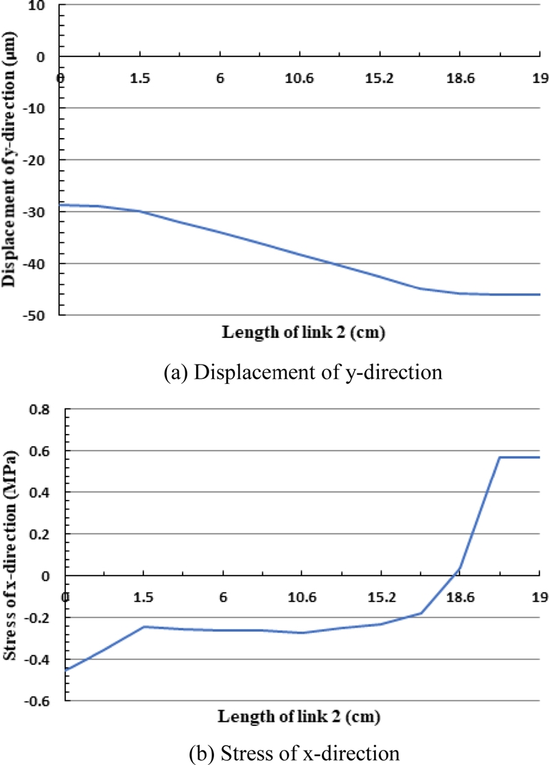
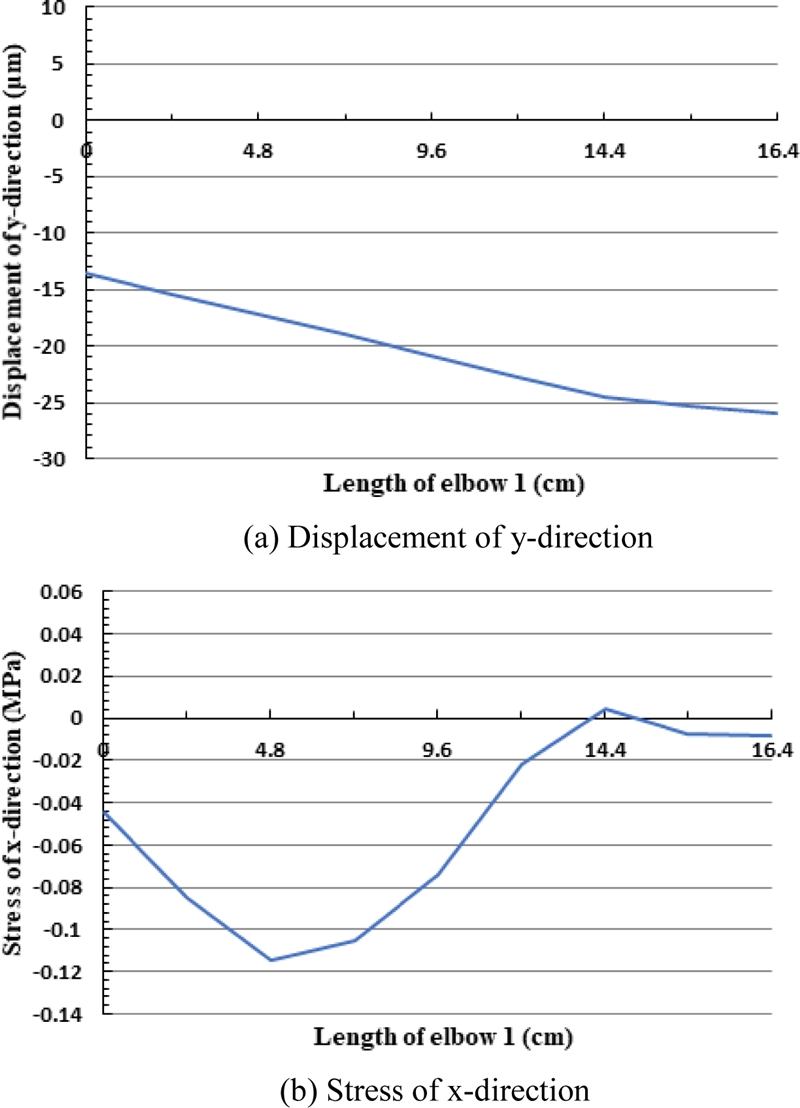
Table 5는 구조해석으로부터 얻은 엘보우1 부품의 변위값와 응력값을 나타내고, 이것들은 엘보우1 부품의 x축 선상(빨간색 표시 부분)의 값이고, 최대 변위와 응력은 각각 -26.01 μm/m와 -0.12 MPa이다. 엘보우1 부품은 916배 정도의 안전율을 가지고 있으므로 매우 안전하다.
Fig. 6은 구조해석으로부터 얻은 엘보우1의 변위와 응력의 그래프를 나타내고,
Fig. 6(a)는 최대 변위가 발생된 y축의 변위 그래프이며,
Fig. 6(b)는 최대 응력이 발생한 x축의 응력 그래프이다.
Table 5Displacement and stress of elbow 1 part obtained from structural analysis
Table 5
|
Direction |
Displacement
[μm] |
Stress
[MPa] |
|
Start P. |
End P. |
Min. |
Max. |
|
x |
3.12 |
4.62 |
0.01 |
-0.12 |
|
y |
-13.60 |
-26.01 |
-0.01 |
0.01 |
|
z |
0.11 |
0.21 |
-0.01 |
0.04 |
Fig. 6Displacement and stress of elbow 1 obtained from structural analysis

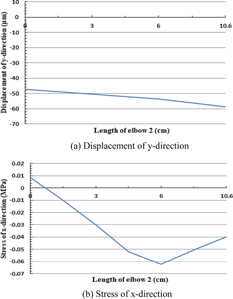
Table 6은 구조해석으로부터 얻은 엘보우2 부품의 변위값와 응력값을 나타내고, 이것들은 엘보우2 부품의 x축 선상(빨간색 표시 부분)의 값이고, 최대 변위와 응력은 각각 -58.59 μm/m와 -0.06 MPa이다. 엘보우2 부품은 매우 큰 안전율을 가지고 있으므로 매우 안전하다.
Fig. 7은 구조해석으로부터 얻은 엘보우2의 변위와 응력의 그래프를 나타내고,
Fig. 7(a)는 최대 변위가 발생된 y축의 변위 그래프이며,
Fig. 7(b)는 최대 응력이 발생된 x축의 응력 그래프이다.
Figs. 5부터
7에서 나타낸 것과 같이 구조해석 결과, 각 부품의 강도가 안전한 것으로 평가하고, 공작물의 중심선 끝점인 ①점과 ②점의 변위가 0.1 mm 이하가 되도록 설계한 것으로 판단한다.
Table 6Displacement and stress of elbow 2 part obtained from structural analysis
Table 6
|
Direction |
Displacement
[μm] |
Stress
[MPa] |
|
Start P. |
End P. |
Min. |
Max. |
|
x |
-3.19 |
3.39 |
-0.06 |
0.01 |
|
y |
-47.09 |
-58.59 |
-0.02 |
0.01 |
|
z |
0.32 |
0.44 |
-0.05 |
0.01 |
Fig. 7Displacement and stress of elbow 2 obtained from structural analysis

2.3 4축 스카라형 로봇의 부품설계
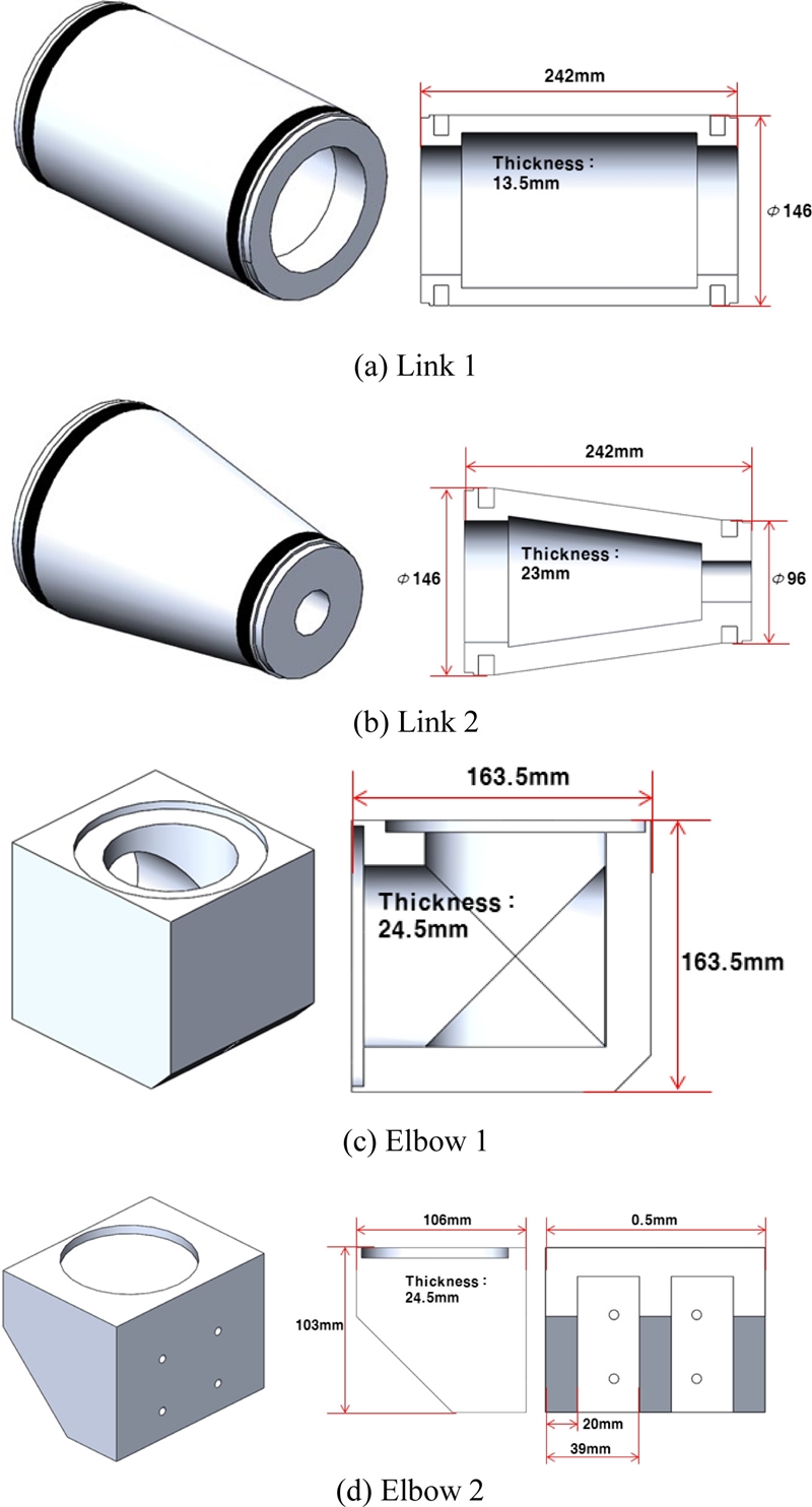
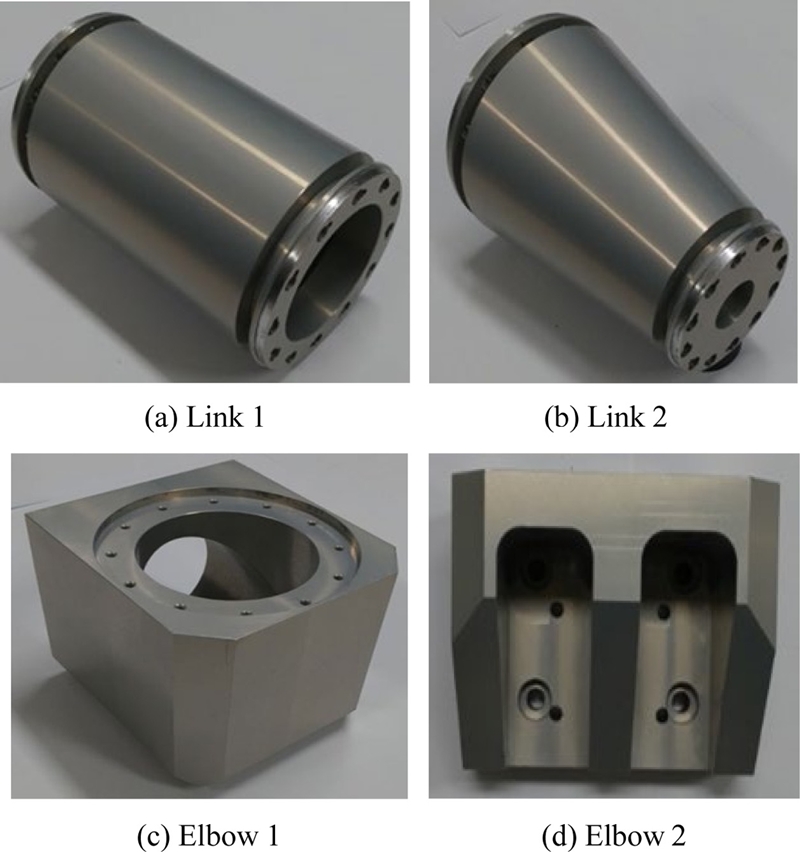
Fig. 8은 설계된 3D 모델링과 크기를 나타낸다.
Fig. 8(a)는 링크1이고, 관절1 모터의 수평 고정구와 엘보우1의 수평 고정구와 각각 볼트로 체결할 수 있도록 양쪽 끝 부분이 플랜지 형태로 모델링하였으며, 두께는 13.5 mm이다.
Fig. 8(b)는 링크2이고, 관절2 모터의 수평 고정구과 관절3 모터의 각 수평 고정구와 볼트로 체결할 수 있도록 양쪽 끝부분이 플랜지 형태로 모델링하였으며, 두께는 23.0 mm이다.
Fig. 8(c)는 엘보우1이고, 이것의 수평 고정구가 링크1과 수직 고정구가 관절2 모터의 수직 고정구와 각각 볼트로 체결할 수 있도록 나사로 가공하고 있으며, 두께는 24.5 mm이다.
Fig. 8(d)는 엘보우2이고, 이것의 수평 고정구가 그리퍼와 수직 고정구가 관절3 모터의 수직 고정구와 각각 볼트로 체결할 수 있도록 나사로 가공하고 있으며, 두께는 24.5 mm이다.
Fig. 8Designed 3D modeling and size of robot parts

3. 4축 스카라형 로봇의 제작 및 특성 시험
3.1 4축 스카라형 로봇의 부품제작
Fig. 9Manufactured robot parts
3.2 4축 스카라형 로봇의 제작
Fig. 10은 제작된 4축 스카라형 로봇을 나타내고, 이것은 관절1 모터, 링크1, 엘보우1, 관절2 모터, 링크2, 관절3 모터, 엘보우2 그리퍼 등의 순서로 연결되어 있으며, 각 부품들은 강력 볼트와 너트로 체결하였다. 제작된 4축 스카라형 로봇은 관절1 모터, 관절2 모터, 관절3 모터가 수직 축을 기준으로 3회전하여 3자유도를 갖고, 이것이 평면상의 정확한 위치로 이동할 때 사용하며, 그리고 그리퍼가 45° 축을 기준으로 180° 회전하여 수평 그리퍼와 수직 그리퍼의 위치가 바뀌게 되고, 이것이 1자유도이다.
Fig. 10Manufactured 4-axis SCARA-type robot
3.3 4축 스카라형 로봇의 실험 및 고찰
Fig. 11Simulation result of the manufactured 4-axis SCARA-type robot
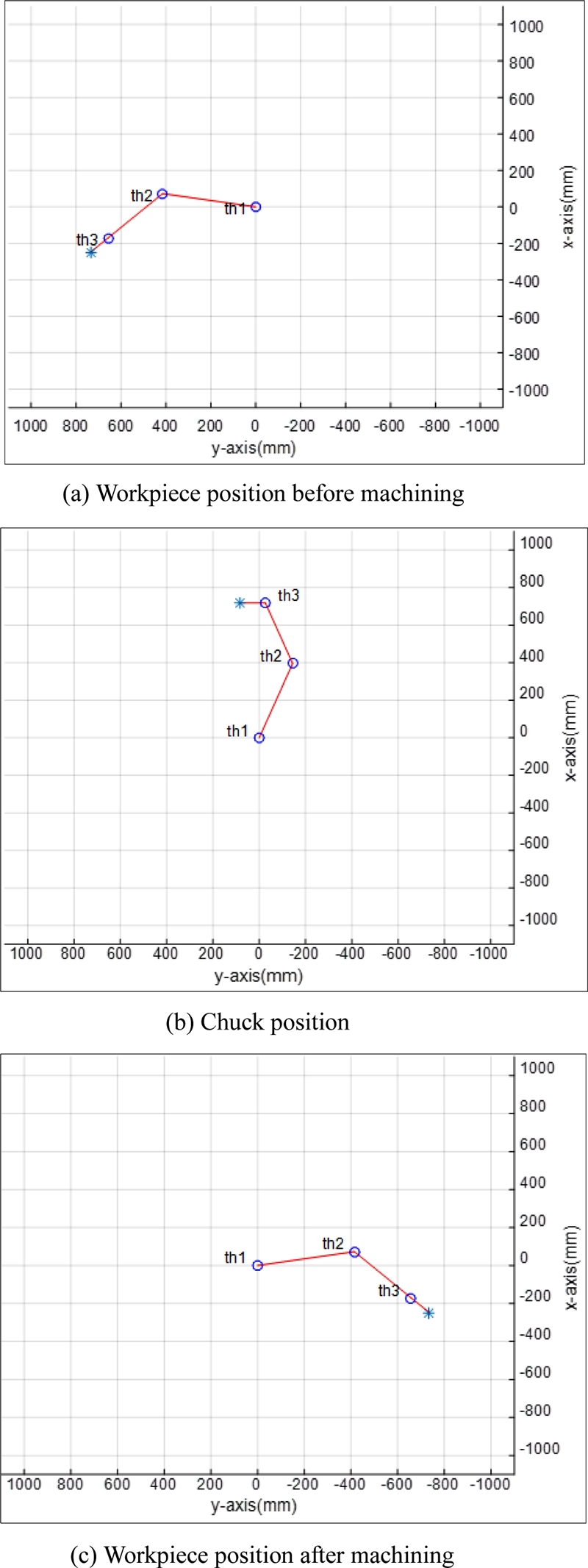
Fig. 12Characteristic test of manufactured 4-axis SCARA-type robot
4. 결론
본 논문에서는 공작기계에 가공 전 공작물과 가공 후 공작물을 로딩 및 언로딩할 수 있는 4축 스카라형 로봇을 설계 및 제작하였다. 4축 스카라형 로봇을 구조해석을 통해 설계한 결과, 수평 그리퍼와 수직 그리퍼에 고정된 공작물의 중심선 끝점의 변위가 0.1 mm 이하고, 변위가 0.1 mm 이하인 조건으로 응력해석을 수행한 링크 및 엘보우 등 로봇 부품의 안전율은 55배 이상으로 매우 높았다. 그러므로 본 논문에서 제작한 4축 스카라형 로봇은 공작기계에 공작물을 로딩 및 언로딩하는데 사용할 수 있을 것으로 판단한다.
추후 연구로는 제작된 4축 스카라형 로봇을 공작기계, 가공 전 공작물 적재 장치, 가공 후 공작물 적재 장치에 설치하여 공작기계에 공작물을 로딩 및 언로딩하는 특성 실험을 실시하는 것이다.
ACKNOWLEDGMENTS
이 논문은 2017년도 정부(미래창조과학부)의 재원으로 한국연구재단의 지원을 받아 수행된 지역신산업선도인력 양성사업 성과임(No. NRF-2016H1D5A1909809).
REFERENCES
- 1.
Zhang, J. and Cai, J., “Error Analysis and Compensation Method of 6-Axis Industrial Robot,” International Journal on Smart Sensing and Intelligent Systems, Vol. 6, No. 4, pp. 1383-1399, 2017.
10.21307/ijssis-2017-595
- 2.
Wu, K., Krewet, C., and Kuhlenkötter, B., “Dynamic Performance of Industrial Robot in Corner Path with CNC Controller,” Robotics and Computer-Integrated Manufacturing, Vol. 54, pp. 156-161, 2018.
10.1016/j.rcim.2017.11.008
- 3.
Shirinzadeh, B., Teoh, P., Tian, Y., Dalvand, M. M., Zhong, Y., et al., “Laser Interferometry-Based Guidance Methodology for High Precision Positioning of Mechanisms and Robots,” Robotics and Computer-Integrated Manufacturing, Vol. 26, No. 1, pp. 74-82, 2010.
10.1016/j.rcim.2009.04.002
- 4.
Wang, S., Miao, X., Yang, Y., and Peng, X., “Error Compensation and Calibration of Inter-Section Line Welding Robot based on a Wavelet Neural Network,” Robotic Welding, Intelligence and Automation, Vol. 88, pp. 33-40, 2011.
10.1007/978-3-642-19959-2_4
- 5.
Pan, Z., Polden, J., Larkin, N., Van Duin, S., and Norrish, J., “Recent Progress on Programming Methods for Industrial Robots,” Robotics and Computer-Integrated Manufacturing, Vol. 28, No. 2, pp. 87-94, 2012.
10.1016/j.rcim.2011.08.004
- 6.
Watanabe, A., Sakakibara, S., Ban, K., Yamada, M., Shen, G., et al., “A Kinematic Calibration Method for Industrial Robots Using Autonomous Visual Measurement,” CIRP Annals, Vol. 55, No. 1, pp. 1-6, 2006.
10.1016/S0007-8506(07)60353-9
- 7.
Gu, J. and De Silva, C., “Development and Implementation of a Real-Time Open-Architecture Control System for Industrial Robot Systems,” Engineering Applications of Artificial Intelligence, Vol. 17, No. 5, pp. 469-483, 2004.
10.1016/j.engappai.2004.03.010
- 8.
Sahu, S., Choudhury, B., and Biswal, B., “A Vibration Analysis of a 6 Axis Industrial Robot Using FEA,” Materials Today: Proceedings, Vol. 4, No. 2, pp. 2403-2410, 2017.
10.1016/j.matpr.2017.02.090
- 9.
Ratcliffe, J. D., Lewin, P. L., Rogers, E., Hatonen, J. J., and Owens, D. H., “Norm-Optimal Iterative Learning Control Applied to Gantry Robots for Automation Applications,” IEEE Transactions on Robotics, Vol. 22, No. 6, pp. 1303-1307, 2006.
10.1109/TRO.2006.882927
- 10.
Baicu, C. F., Rahn, C. D., and Dawson, D. M., “Backstepping Boundary Control of Flexible-Link Electrically Driven Gantry Robots,” IEEE/ASME Transactions on Mechatronics, Vol. 3, No. 1, pp. 60-66, 1998.
10.1109/3516.662869
- 11.
Christoforou, E. G. and Damaren, C. J., “Application of Passivity-Based Techniques to the Control of Structurally Flexible Gantry Robots,” Proc. of the IEEE International Conference on Robotics and Automation, pp. 324-329, 2011.
10.1109/ICRA.2011.5979803
- 12.
Chen, F. F. and Su, Q., “Scheduling Single-Gripper Gantry Robots in Tightly Coupled Serial Production Lines: Optimum vs. Push/Pull Concept Based Sequences,” Journal of Manufacturing Systems, Vol. 14, No. 3, pp. 139-147, 1995.
10.1016/0278-6125(95)98882-7
- 13.
Baicu, C. F. and Rahn, C. D., “Active Boundary Control of a Flexible Single Link Gantry Robot,” IFAC Proceedings Volumes, Vol. 29, No. 1, pp. 103-108, 1996.
10.1016/S1474-6670(17)57646-6
- 14.
Flixeder, S., Glück, T., Böck, M., and Kugi, A., “Model-Based Signal Processing for the Force Control of Biaxial Gantry Robots,” IFAC-PapersOnLine, Vol. 50, No. 1, pp. 3208-3214, 2017.
10.1016/j.ifacol.2017.08.439
- 15.
İrem, K., Öztürk, S., and Kuncan, M., “Pantography Application with Real-Time PLC based on Image Processing in Gantry Robot System,” European Journal of Technique, Vol. 9, No. 2, pp. 219-229, 2019.
Biography
- Seong-Gyu Yang
M.S. candidate in the Department of Control & Instrumentation Engineering, Gyeongsang National University. His research interest is indusrial robot and Intelligent robot.
- Gab-Soon Kim
Professor in the Department of Control & Instrumentation Engineering, Gyeongsang National University. His research interest is walking aid robot and intelligent robot.