ABSTRACT
This research is to investigate the cooling performance of the motor in the electric vehicle depending on the cooling channel fin. The research focused on numerical study of the temperature of coil and cooling channel and the heat transfer coefficients to find a optimum design shape with high cooling performance at three different cases. To compare the convective cooling performance of the three cooling channels, local position (R) are displayed on the surface of the coils with a large temperature deviation. This research was performed on forced convection and was numerically analyzed by FLUENT V20.2. Owing to forced convection by the same mass flow, the average cooling channel velocity in Case 3 was 17.4% faster than Case 1 and 8.6% faster than Case 2. Out of the three cases, the highest heat transfer coefficient was found in the cooling channel and coil of Case 3, which had two cooling fins. The coil maximum temperature of Case 3 with 2 cooling fins was 4.7% lower than Case 1 without cooling fins and 1.7% lower than Case 2 with 1 cooling fin. Ultimately, Case 3 with two cooling fins provided the best cooling performance and improved driving motor performance for motor durability.
-
KEYWORDS: Electric vehicle, Drive motor, Computational fluid dynamics, Cooling performance, Cooling fin, Convective cooling
-
KEYWORDS: 전기자동차, 구동 모터, 전산 유체 역학, 냉각 성능, 방열핀, 대류 냉각
1. 서론
최근 심각한 지구 온난화와 대기오염으로 인한 환경 문제는 세계에서 크게 대두되고 있는 가운데 화석연료의 연소로 인한 CO
2, SO
2, NO
X 등의 배기가스 배출이 주된 원인이라고 할 수 있다. 이러한 이유 때문에 전 세계적으로 미래형 자동차의 방향은 온실 가스 배출을 저감하는 것을 목표로 하고 있다. 현재 내연 기관을 대체할 수 있는 미래형 친환경 자동차의 대표 주자인 전기자동차의 개발 및 연구가 활발히 이루어지고 있는 중이다. 이에 따라 전기자동차의 동력원인 구동 모터의 개발이 필수적이다. 최근에는 고효율, 대용량화, 경량화, 소형화된 전기자동차 모터의 요구가 크게 증가하고 있다. 소형화된 모터의 경우 방열 면적이 감소하여 내부온도가 증가하게 되어 기존의 모터들보다 냉각 성능을 향상시켜줄 필요가 있다. 모터의 냉각 성능을 향상시키기 위해서는 모터 내부의 냉각 채널과 코일의 온도를 중점으로 연구하여야 한다. 실제 모터 내부의 주 발열체는 코일이며, 코일은 일정 온도 이상이 되면 변형을 동반하며 소손이 발생하게 되어 기능을 상실하게 된다. 모터의 구성 부품 중 코일에서의 발열량이 가장 많고, 코일의 온도에 따라 회전자 내부에 삽입되어 있는 영구 자석의 성능과 모터의 성능이 결정되기 때문에 냉각 채널을 통해 코일의 발열을 감소시켜야 한다. 전기자동차 모터에 사용되는 영구 자석은 자동차뿐만 아니라 모빌리티 분야에서 다양하게 사용되는 것으로 높은 자속 밀도로 인해 높은 토크 밀도를 생성할 수 있는 Nd 계열의 희토류 영구 자석이다. 여기서의 영구 자석은 높은 온도에서 영구 감자가 될 수 있는 변곡점이 나타나 외부 자계에 의해 영구 감자가 발생하게 되어 영구 자석의 성능, 모터의 성능이 감소될 수 있다.
1 따라서 전기자동차의 모터 코일의 발열을 최소로 유지하여 모터의 성능을 향상되도록 하여야 한다.
전기자동차 모터의 냉각에 관한 기존 연구들은 전기모터 회전자의 유동해석 및 냉각 구조 연구,
2 IPM 영구 자석 모터의 냉각 채널 탑재에 따른 열 특성 연구,
3 구동 모터에 히트파이프를 부착하여 냉각 성능을 비교한 연구,
4 냉각 채널의 입구 및 출구의 개수와 위치, 냉각 채널의 회전 횟수에 따른 냉각 성능 연구,
5 HEV용 모터 내부 오일 분사를 통한 냉각 성능에 관한 연구,
6 방열핀 형상에 따른 자동차용 모터 하우징의 냉각 성능에 관한 연구,
7 고출력 모터에서의 공냉, 수냉 및 유냉의 냉각 성능을 비교한 연구,
8 영구 자석을 탑재한 모터를 이용한 고속 터보 공기압축기에서의 냉각 채널의 형상에 따른 열유동을 비교한 연구,
9 FSI 해석기법을 활용한 냉각 채널에 따른 고속 주축계의 열 특성에 관한 연구,
10 고정자 내부에 탑재된 냉각 채널에 따른 냉각 성능 연구
11 등이 있지만 실제 차량용 모터의 냉각 채널의 방열핀에 따른 코일의 온도를 기준으로 냉각 성능을 비교하는 연구는 거의 수행되지 않았다.
본 연구는 전기자동차 모터의 방열핀 부착에 따른 냉각 채널을 이용한 강제 대류 냉각 시스템에서 방열핀이 부착되지 않은 냉각 채널과 방열핀이 1, 2개 부착되는 냉각 채널을 설계하여 냉각 채널 및 코일의 온도를 수치적으로 해석하여 강제 대류 열전달을 통해 위치별 냉각 성능 분석 및 가장 우수한 냉각 성능을 가지는 Case를 설계하고, FSI 해석기법을 통한 코일에서의 열변형 정도를 해석할 것이다. 또한 냉각 성능이 취약한 위치와 우수한 위치를 파악 및 분석하고, 질량 유량에 따른 냉각 채널 및 코일의 온도 변화와 냉각 채널 내부의 압력 강하를 고려하여 최적의 유량을 가진 스마트 냉각 시스템을 설계하는 것이 이번 연구의 목표이다.
2. 유동해석 모델 및 설계
Fig. 1은 국내 완성차 업체 K사의 전기자동차 모델 N에 탑재되는 구동 모터 사진이며,
Fig. 2는
Fig. 1의 모델 N을 직접 분해 및 실측하여 CATIA V5 R21로 모델링한 CAD 형상을 렌더링한 사진이다. 냉각 채널의 입구, 출구 및 냉각 채널 내부의 기본적인 형상은 모델 N에 탑재된 형상과 상이하게 설계하였고, 동력 전달 축, UVW Connector, 코일의 양끝단, 하우징 외부의 굴곡진 부분 등 전기자동차 모터 냉각 채널의 강제 대류 유동해석에 큰 영향을 미치지 않는 부분은 단순화하여 하우징, 냉각 채널, 고정자, 코일, 회전자, 영구 자석, 동력 전달 축을 3D 모델링하였다.
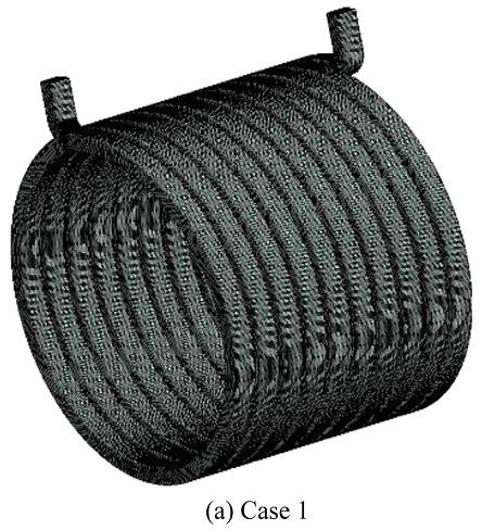
Fig. 3은 이번 연구에서 다루는 냉각 채널의 3가지 형상을 CATIA V5 R21로 모델링한 후 ANSYS V20.2로 불러온 사진이다.
Figs. 3(a)는 냉각 채널 내부에 방열핀이 부착되지 않은 냉각 채널이며,
3(b)는 냉각 채널 내부의 입구부터 출구까지 연결된 방열핀이 1개,
3(b)는 방열핀이 2개 부착된 형상이다.
Fig. 3의 3가지 Cases 모두 냉각 채널 내부 방열핀의 개수만 다르게 설계하였고, 냉각 채널의 기본적인 형상, 하우징, 고정자, 코일, 회전자, 영구 자석, 동력 전달 축은 동일한 위치와 크기로 설계하였다. 모터의 앞부분(코일의 길이 방향)을 +Z 방향으로 두고 설계하였다.
Table 1은 CATIA V5 R21을 활용하여 모델링한 하우징, 고정자, 코일, 회전자, 영구 자석, 동력 전달 축의 실물 크기와 개수를 표로 나타낸 것이다.
Fig. 1 Actual picture of electric motor model N
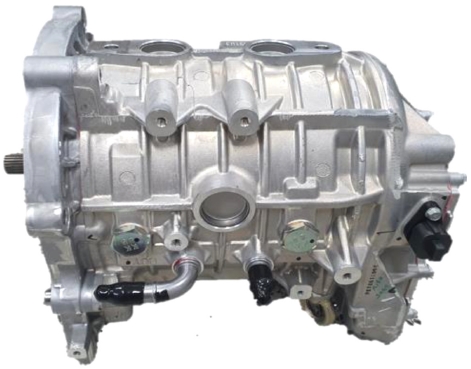
Fig. 2 Completed CATIA rendering of electric motor geometry
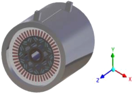
Fig. 3 Imported geometries of cooling channel at three different cases with/without fins
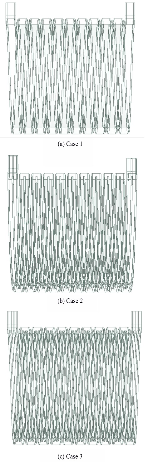
Table 1 Physical dimensions of electric motor model N
Table 1
|
Width (L)
[mm] |
Thickness (T)
[mm] |
Height (H)
[mm] |
EA |
|
Magnet |
16 |
3 |
175 |
16 |
|
12 |
5 |
175 |
16 |
|
Coil |
20 |
6 |
175 |
48 |
|
Diameter internal /
external (D) [mm] |
Height (H) [mm] |
EA |
|
Rotor |
50/132 |
175 |
1 |
|
Stator |
133.4/199.4 |
175 |
1 |
|
Shaft |
32/50 |
175 |
1 |
|
Housing |
199.4/235.4 |
260 |
1 |
2.1 유동 및 경계 조건
해석 조건은 전기자동차 모터 냉각 채널에서의 유체의 열전달 및 유동해석과 전기자동차 모터 전체에서의 열전달 해석을 진행하기 위해 에너지 보존 법칙, 질량 보존법칙, 운동량 보존 법칙을 ANSYS FLUENT V20.2로 비압축성 정상 상태 유동해석을 진행하였다. 모터 냉각 채널의 내부 유동의 최대 레이놀즈 수는 5,082으로 계산되었고, 이에 따라 난류 유동해석을 진행하였다. 또한 유체의 유동 경계층 흐름에 대한 더 많은 계산을 수행하고, 해석 결과의 정확도를 증가시키기 위해 k-omega SST 모델을 사용하였다.
초기 조건으로 모터 하우징 외부 경계 조건은 단열 조건으로 설정하였으며 모터 내부 공극 사이의 공기의 온도는 상온을 기준으로 하여 298.15 K으로 설정하였고, 냉각 채널의 입구로 유입되는 냉각수의 온도는 차량이 실제 운행 중일 때와 유사한 조건으로 해석을 수행하기 위해 338.15 K으로 설정하였다. 모터에서 대중적으로 사용하고 있는 냉각수의 유량 6.5 LPM을 채택하여 질량 유량으로 변경하여 3가지 Cases 모두 동일하게 냉각 채널 입구에서의 질량 유량을 0.106 kg/s로 설정하였다. 출구는 모두 대기압으로 가정하여 계기 압력 0 Pa을 부여하였다. 전기자동차 모터 내부의 코일에 일정 열유속 조건을 열 경계 조건으로 사용하였다. 코일의 발열량은 방열핀이 부착되지 않는 냉각 채널을 탑재한 모터에서 코일의 허용 최고온도를 발생시킨 발열량 1,000,000 [W/m
3]을 설정하였다.
Table 2는 열 및 유동해석을 진행하기 위한 경계 조건들을 표로 정리한 것이다. 냉각 채널에 유입되는 냉각수는 실제 사용하고 있는 물과 1 : 1 비율로 혼합한 Ethylene Glycol을 선택하였고, ANSYS FLUENT V20.2에 입력한 Ethylene Glycol, 하우징, 고정자, 코일, 회전자, 영구 자석, 동력 전달 축의 밀도, 비열, 열전도율, 점성 계수의 물성치들을
Table 3에 나열하였다.
Table 2Design boundary conditions
Table 2
|
Fluid material |
Air |
Incompressible |
|
Ethylene glycol |
|
Inlet (Ethylene glycol) |
Mass flow rate [kg/s] |
0.106 |
|
Temperature [K] |
338.15 |
|
Inlet (Air) |
Temperature [K] |
298.15 |
|
Outlet (Ethylene glycol) |
Pressure [Pa] |
0 |
|
Outlet (Air) |
Pressure [Pa] |
0 |
|
Coil |
Heat generation [W/m3] |
1,000,000 |
Table 3Thermophysical property of material
Table 3
|
Density
[kg/m3] |
Thermal conductivity
[W/m·K] |
Specific heat
[J/kg·K] |
|
Ethylene glycol |
1,057 |
0.394 |
3,410 |
|
Viscosity [kg/m·s] |
0.00159 |
|
Housing |
2,790 |
168 |
883 |
|
Stator and Rotor |
7,540 |
31 |
557 |
|
Coil |
8,933 |
401 |
385 |
|
Magnet |
7,500 |
7.5 |
410 |
|
Shaft |
7,817 |
51.9 |
446 |
2.2 격자 의존도 검증
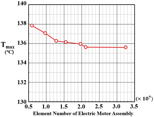
전기자동차 모터의 구성 부품들의 격자가 서로 원활하게 연결되어 해석 진행에 있어 오류가 없도록 하여야 한다. 모터 전체의 격자 수는 대략 600만개에서 3,200만개의 격자를 생성하여 모터 내부 코일의 최고온도를 기준으로 격자 의존도 검사를 진행하였다. 전기자동차 모터의 총 격자 수에 따른 오차율을
Table 4에 정리하였고, 격자 의존도 검증의 결과는
Fig. 4의 그래프를 통하여 나타내었다. 해석 시간 및 효율성을 고려하여 2,119만개 격자가 적절하다고 판단하여 해당 격자를 활용하였다.
Table 4Total elements of electric motor assembly for grid dependency
Table 4
|
Total elements |
Tmax [oC] |
Error [%] |
|
5,927,164 |
137.85 |
1.73 |
|
9,693,383 |
137.07 |
1.16 |
|
12,816,823 |
136.26 |
0.56 |
|
15,497,764 |
136.13 |
0.47 |
|
19,702,867 |
135.96 |
0.34 |
|
21,199,614 |
135.62 |
0.09 |
|
32,475,765 |
135.60 |
0.07 |
Fig. 4Grid dependency test
2.3 격자 생성
ANSYS MESH를 이용하여 수치해석을 위한 격자를 생성하였다.
Figs. 5는 전기자동차 모터 전체의 격자 형상이고,
6은 3의 Case 1의 냉각 채널 격자 형상이며, 7은 3가지 Cases의 냉각 채널 단면 격자 형상이다.
Figs. 7(a)는 냉각 채널에 방열핀이 부착되지 않은 냉각 채널,
7(b)는 방열핀이 1개,
7(c)는 방열핀이 2개 부착되는 냉각 채널의 단면 형상이다. 하우징, 회전자, 영구 자석, 동력 전달 축은 Tetra 격자를 사용하고, 고정자와 냉각 채널은 Hexa 격자를 사용하였다. 냉각 채널 내부 냉각수의 경우 벽면에서 속도 구배가 매우 크기 때문에 조밀한 격자를 필요로 하여 입구, 출구를 제외한 모든 면에 Inflation을 사용하였다.
Fig. 3의 Cases 1과 2의 냉각 채널의 경우 벽면에서의 격자 층수를 4층, Growth Rate를 1.2로 설정하였고, 최대두께를 1 mm로 설정하였다. 냉각 채널에 Body Sizing으로 1 mm를 설정하였다.
Fig. 3의 Case 3의 경우 Cases 1과 2보다 냉각 채널의 단면적이 좁아 동일한 질량 유량에 대한 냉각수의 속도가 빠르기 때문에 벽면의 격자 층수를 6층, Growth Rate를 1.2로 설정하였고, 최대두께를 1 mm로 설정하였다. 냉각 채널은 Body Sizing을 1 mm로 설정하였으며, 코일에는 Multizone의 Tetra/Pyramid 격자를 사용하였고, Body Sizing으로 1 mm로 설정하였다. 하우징과 축은 10 mm, 영구 자석과 회전자는 5 mm로 Body Sizing을 설정하였다. 고정자는 Body Sizing으로 1.5 mm로 설정하였다. 코일은 3가지 Cases 모두 동일한 조건을 입력하여 코일의 격자 수는 103만개로 동일하였다.
Fig. 3의 Case 1의 냉각 채널 격자 수는 272만개, 총 격자 수는 2,119만개, Case 2의 냉각 채널의 격자 수는 199만개 총 격자 수는 2,043만개, Case 3의 냉각 채널의 격자 수는 457만개 총 격자 수는 2,324만개를 생성하여 이를
Table 5에 정리하였다. 냉각 채널에서의 Y
+는 0-6.4, 평균 값은 0.1을 유지하였다.
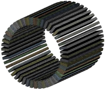
Fig. 8은 3가지 Cases에 모두 동일하게 탑재되는 코일의 격자 형상이다.
Fig. 5Total mesh generation of electric motor model N
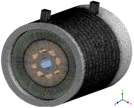
Fig. 6Mesh generation of cooling channel

Fig. 7Mesh generation of cooling channel sections with/without cooling fins
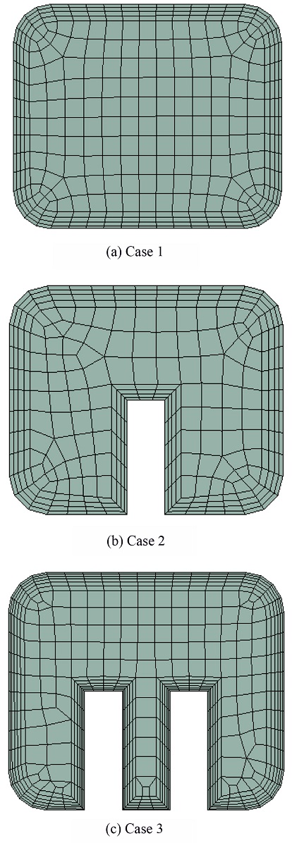
Table 5Number of elements in cooling channel and coil
Table 5
|
Case 1 |
Case 2 |
Case 3 |
|
Cooling channel |
Coil |
Cooling channel |
Coil |
Cooling channel |
Coil |
|
Method |
Hexa |
Tetra/Pyramid |
Hexa |
Tetra/Pyramid |
Hexa |
Tetra/Pyramid |
|
Elements |
2,720,240 |
1,032,150 |
1,992,425 |
1,032,150 |
4,578,427 |
1,032,150 |
|
Total |
|
21,199,614 |
20,438,472 |
23,245,756 |
Fig. 8Mesh generation of coil
3. 결과 및 고찰
본 연구에서는 CATIA V5 R21를 통해 K사의 전기자동차 모델 N의 모터 형상을 단순화하였고, ANSYS FLUENT V20.2를 활용하여 냉각 채널에서의 수치해석을 진행하였다. 정확한 계산과 해석의 신뢰성을 확인하기 위해 KIST의 Intel Xeon Phi 7250 1.4 GHz 모델 68 코어 96 GB, 6Ch per CPU의 성능을 가진 슈퍼컴퓨터를 사용하였다. 냉각 채널에 방열핀이 부착되지 않은 형상, 방열핀이 1개, 방열핀이 2개 부착된 형상으로 분류하여 냉각 채널에서의 강제 대류 열전달 메커니즘에 의한 수치해석을 진행하였다.
방열핀을 제외한 모터의 부품들은 3가지 Cases 모두 동일하게 설계하였다. 해석 이후 유동해석의 경향과 신뢰성을 확인하기 위해 냉각 채널 내부의 속도 분포와 온도 분포를 분석하였다. 또한 모터 내부 코일에서의 온도 분포를 분석하고, 온도 분포의 편차가 가장 큰 국소적 위치에서 열전달 계수(h) 해석을 진행한 후 방열핀 부착에 따른 냉각 성능을 비교하여 3가지 Cases 형상 중 냉각 성능이 가장 우수한 형상을 선정하였다. 또한 선정한 형상을 기준으로 기존에 입력한 질량 유량을 일정 비율로 감소 및 증가시켜 냉각수의 질량 유량에 따른 전기자동차 모터의 냉각 성능을 비교하여 최적의 질량 유량을 선정하였다. 마지막으로 FSI 해석기법을 통해 전기자동차 모터 내부의 발열원인 코일에서의 열변형 정도를 확인하였다.
3.1 속도 분포
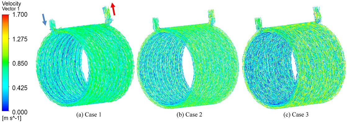
Fig. 9는 방열핀 부착에 따른 냉각 채널 내부 냉각수의 속도 벡터 분포를 3차원으로 나타낸 그림이다. 동일한 질량 유량(0.106 kg/s)에 대해 냉각 채널 입구의 냉각수 속도는
Figs. 9(a)는 0.588 m/s,
9(b)는 0.632 m/s,
9(c)는 0.684 m/s로 계산되었다. 냉각 채널의 입구 면적이 가장 좁은
Fig. 9(c)의 입구 속도가 가장 빠르게 나타났다. 냉각 채널 내부 냉각수의 최고속도는
Figs. 9(a)에서 1.112 m/s,
9(b)에서 1.286 m/s,
9(c)에서 1.437 m/s로 모두 출구 주변 위치에서 나타났다. 최고속도 또한 입구 속도와 동일하게 냉각 채널 내부의 면적이 가장 좁은 방열핀이 2개 부착된 형상에서 나타났다. 냉각 채널 내부 냉각수의 평균속도는
Figs. 9(a)에서 0.593 m/s,
9(b)에서 0.641 m/s,
9(c)에서 0.696 m/s로 나타났다. 평균속도는
Figs. 9(c)가
9(a)에 비해 17.4% 정도 빠르고,
9(b)에 비해 8.6% 정도 빠르게 나타나 평균속도 또한 입구 속도 및 최고속도와 동일하게 방열핀이 2개 부착된 형상에서 가장 빠르게 나타났다.
Fig. 9Velocity vectors at three different cases of cooling channel (Ethylene glycol)

3.2 온도 분포
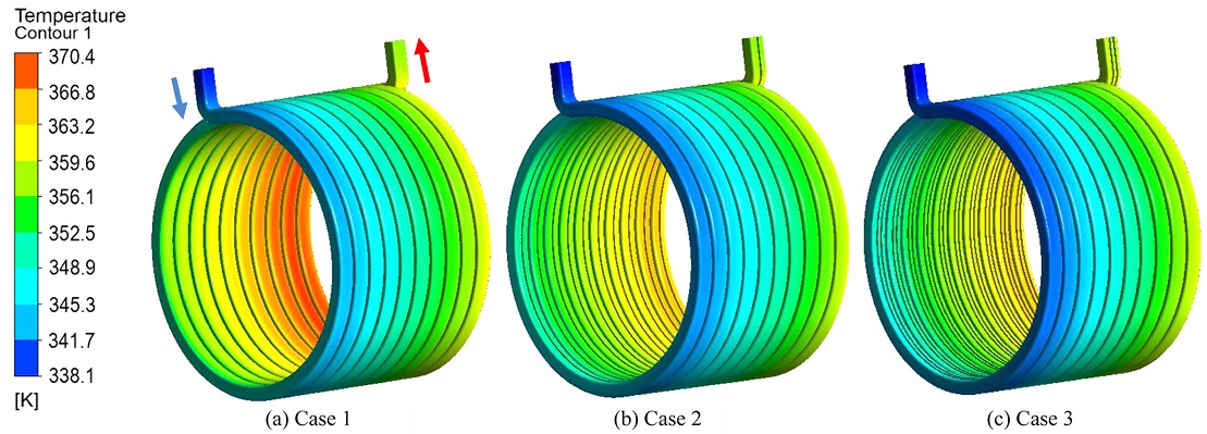
Fig. 10은 방열핀 부착에 따른 냉각 채널에서의 온도 분포를 나타낸 그림이다. 3가지 Cases 모두 동일한 위치에서 최저온도, 최고온도가 나타났다. 냉각 채널 입구에서 냉각수 초기온도 65
oC로 가장 낮은 온도가 나타났고, 최고온도는 냉각 채널 출구에 인접한 가장 냉각 성능이 취약한 코일과 가까운 위치에서 나타났다. 냉각 채널의 최고온도는
Figs. 10(a)에서 102.76
oC,
10(b)에서 98.31
oC,
10(c)에서 97.22
oC로 나타났다. 최고온도는
Figs. 10(c)가
10(a)에 비해 5.54
oC,
10(b)에 비해 1.09
oC 낮게 나타나 냉각 성능이 가장 우수한 냉각 채널이라고 판단된다.
Fig. 10Temperature contours at three different cases of cooling channel

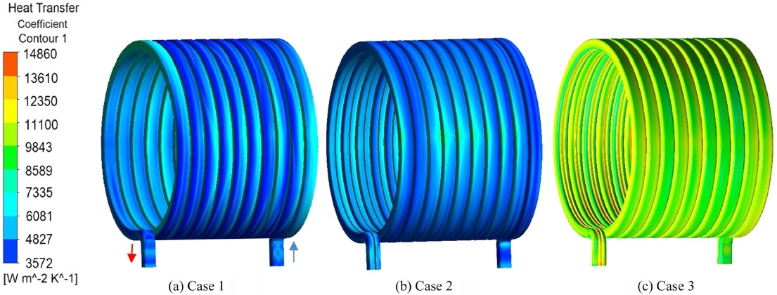
Fig. 11Wall heat transfer coefficient contours at three different cases of cooling channel

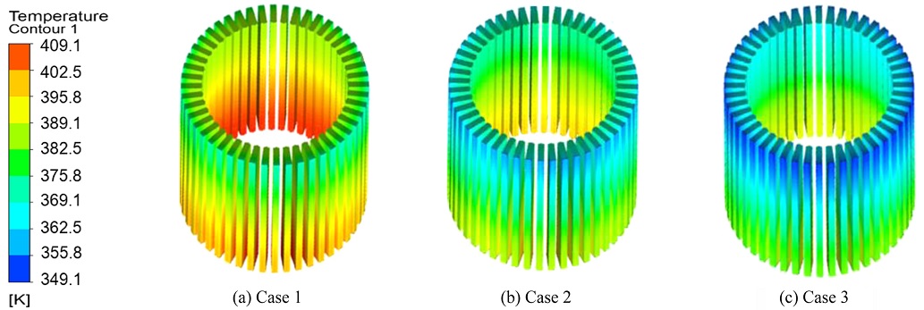
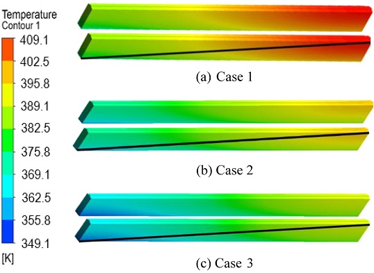
Figs. 12는 10의 방열핀 부착에 따른 냉각 채널을 통해 얻은 수치해석 결과에서 코일의 표면 온도 분포를 나타내는 그림이다.
Figs. 12(a)는 방열핀이 부착되지 않은 냉각 채널을 탑재한 코일의 표면 온도 분포를 나타낸 것이고,
12(b)는 방열핀이 1개,
12(c)는 방열핀이 2개 부착된 냉각 채널을 탑재한 코일의 표면온도 분포를 나타낸 것이다.
Fig. 12의 3가지 Cases 모두 최저온도와 최고온도는 동일한 위치에서 나타났으며, 최저온도는 냉각 채널의 입구와 가장 인접한 위치, 최고온도는 냉각 채널의 출구 쪽의 채널 벽면에서 가장 떨어진 위치에서 나타났다.
Fig. 12(a)에서 최고온도 135.62
oC, 최저온도 119.6
oC, 온도 편차 16.02
oC로 나타났다.
Figs. 12(b)에서 최고온도 131.52
oC, 최저온도 114.43
oC, 온도 편차 17.09
oC,
12(c)에서 최고온도 129.28
oC, 최저온도 112.47
oC, 온도 편차 16.81
oC로 나타났다.
Figs. 12(c)가
12(a)에 비해 최고온도 4.7%(6.34
oC), 최저온도 6%(7.13
oC) 낮게 나타났고,
12(b)에 비해 최고온도 1.7%(2.24
oC), 최저온도 1.7% (1.96
oC) 낮게 나타났다. 코일의 평균온도는
Figs. 12(a)에서 130.12
oC,
12(b)에서 125.7
oC,
12(c)에서 122.93
oC로 나타났다.
Figs. 12(c)의 평균온도가
12(a)에 비해 5.5%(7.19
oC),
12(b)에 비해 2.2%(2.77
oC) 낮게 나타났다. 모터 내부의 코일 표면 온도를 비교해본 결과 냉각 채널에 방열핀이 부착되지 않은
Figs. 12(a)의 냉각 성능이 가장 취약하고, 방열핀 2개를 부착한
12(c)의 냉각 성능이 가장 우수한 것을 확인할 수 있었다.
Fig. 12Temperature contours at three different cases of coil surface

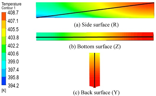
Figs. 13은
12의 코일의 표면들 중에서 온도 분포의 편차가 가장 큰 표면을 찾기 위해
Fig. 12의 Case 1의 코일을 옆면(R), 아랫면(Z), 뒷면(Y)으로 총 3가지로 구분하여 각 면의 위치에서 온도 분포의 편차가 가장 큰 방향을 기준으로 무차원 기준 길이(R
+, Z
+, Y
+)를 설정하여 11개 지점으로 나누어 코일 표면의 온도 분포를 나타내는 그림이다.
Figs. 13(a)는 코일의 옆면,
13(b)는 아랫면,
13(c)는 뒷면을 나타내는 그림이다.
Fig. 13Temperature distributions on three sides of coil surface
식(1)에서의 R은 코일의 옆면 대각선 위의 국소적 위치, L은 대각선의 전체 길이, Z는 아랫면 코일 길이 방향에서의 국소적 위치, I는 아랫면 코일 길이 방향의 전체 길이, Y는 코일 뒷면 높이에서의 국소적 위치, H는 뒷면 코일 높이의 전체 길이이다.
3개의 면에서 11개의 각 지점에 대한 코일의 표면 온도는
Table 6에 나타나 있다. 앞면과 윗면에서의 코일의 표면 온도 편차는 뒷면, 아랫면에 비해 대부분 일정하기 때문에 제시하지 않았다.
Table 6에 제시한 것처럼 코일의 옆면, 아랫면, 뒷면에서의 최고온도는 134.85
oC로 동일하며 온도 편차의 범위는 옆면에서 120.85-134.85
oC, 아랫면에서 126.85-134.85
oC, 뒷면에서 131.85-134.85
oC로 나타나 온도 편차의 범위는
Fig. 13의 옆면(R)에서 가장 크게 나타났다. 따라서 방열핀 부착에 따른 냉각 채널에서의 코일 온도를 비교하는 기준은 코일의 표면 중 옆면으로 선택하였다.
Table 6Temperature distribution on three sides of coil
Table 6
|
Case 1 |
R+
Normalized
position |
TS
[K] |
Z+
Normalized
position |
TS
[K] |
Y+
Normalized
position |
TS
[K] |
|
0 |
394 |
0 |
400 |
0 |
405 |
|
0.1 |
397 |
0.1 |
400 |
0.1 |
406 |
|
0.2 |
398 |
0.2 |
401 |
0.2 |
407 |
|
0.3 |
400 |
0.3 |
402 |
0.3 |
407 |
|
0.4 |
402 |
0.4 |
404 |
0.4 |
408 |
|
0.5 |
404 |
0.5 |
405 |
0.5 |
408 |
|
0.6 |
405 |
0.6 |
406 |
0.6 |
408 |
|
0.7 |
406 |
0.7 |
407 |
0.7 |
408 |
|
0.8 |
407 |
0.8 |
408 |
0.8 |
408 |
|
0.9 |
408 |
0.9 |
408 |
0.9 |
408 |
|
1 |
408 |
1 |
408 |
1 |
408 |
Figs. 14는
12에 나타나있는 3가지 Cases의 코일에서 온도 분포의 편차가 가장 큰 코일 표면의 온도를 비교하기 위해 나타낸 그림이다. 방열핀 부착에 따른 냉각 채널의 3가지 형상에 대하여 동일한 위치의 코일 표면에서 온도 분포의 편차가 가장 크며 온도 분포가 대각선 방향으로 뚜렷하게 변화하여 선을 긋고, 대각선상에서 일정한 간격으로 11개 지점을 나누어 코일 표면에서의 온도 분포를 분석하였다.
Fig. 14Temperature contours of diagonal position (R+) on the coil surface with maximum temperature deviation at three different cases of coil surface
냉각 성능이 취약하고, 온도 분포의 편차가 가장 큰 코일의 표면에서의 국소적 위치(R)에 따라 냉각 성능을 정량적으로 비교하기 위해 Nusselt 수를 계산하였다. Nusselt 수는 열전달 계수(h)의 무차원 파라미터로 강제 대류 열전달에 대한 유체 내의 전도 열전달의 상대적인 비를 나타내는 무차원 파라미터이다.
식(2)에서의 T
3(min)은 3가지 Cases 중 냉각 성능이 가장 우수하게 나타난 방열핀이 2개 부착된 냉각 채널을 탑재한 모터에서 냉각 성능이 가장 우수한 코일의 표면(R
+ = 0) 온도이다. T
c는 Case별 국소적 위치에서의 코일 표면 온도이다. T
+로 무차원화하여 비교한 이유는 냉각 성능이 가장 우수하게 나타난 코일 표면에 비하여 다른 코일의 표면 온도는 어느 정도 증가하였는지 3가지 Cases의 온도 분포의 차이를 정량적으로 비교하기 위해서이다.
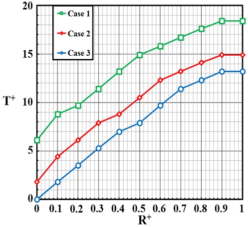
Figs. 15는
14의 냉각 성능이 취약하고 온도 분포의 편차가 가장 큰 코일 표면의 대각선상의 위치별로 코일의 표면 온도를 비교하기 위해 T
+로 무차원화하여 냉각 성능이 가장 우수하게 나온 코일의 표면(Case 3의 R
+ = 0 지점)에 비해 다른 코일 표면의 냉각 성능 정도를 국소적인 위치(R
+)에 대해 한눈에 비교하기 위해 정량적으로 나타낸 그래프이다. 무차원의 기준 길이(R
+)를 코일의 좌측 모서리 하단(R
+ = 0)에서 시작하여 코일의 우측 모서리 상단(R
+ = 1)을 0-1로 설정하였다. R
+ = 0은 냉각 채널에서 냉각수가 유입되는 입구에서 가장 인접한 코일 부분이고 R
+ = 1은 냉각수가 냉각 채널 외부로 유출되는 출구에 가장 인접한 코일 부분이다.
Fig. 15를 보면 3가지 Cases 모두 R
+ = 0에서 R
+ = 1로 갈수록 T
+가 증가하여 냉각 성능이 떨어지는 것을 알 수 있다.
Fig. 15의 Case 1은 방열핀이 부착되지 않은 냉각 채널을 탑재한 코일, Case 2는 방열핀이 1개, Case 3은 방열 핀이 2 개 부착된 냉각 채널을 탑재한 코일의 그래프를 나타낸다.
Fig. 15의 Case 1의 코일 표면 온도는 냉각 성능이 가장 우수한 코일의 표면(Case 3의 R
+ = 0 지점)에 비해서 가장 낮게는 6.1%, 가장 높게는 18.4% 증가하였다.
Fig. 15의 Case 2는 1.8-14.9% 증가하였고, Case 3은 0-13.2% 증가하였다.
Fig. 15의 Case 3에서 온도 증가 비율이 가장 낮은 것으로 보아 냉각 채널에 방열핀을 2개 부착하였을 때 코일의 냉각 성능이 가장 우수하다는 것을 알 수 있다.
Fig. 15Dimensionless coil temperature vs. position at three different cases of coil surface
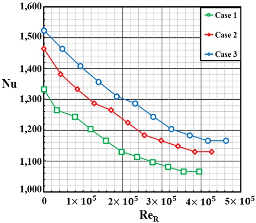
Figs. 16은
14의 3가지 Cases의 레이놀즈 수(Re
R)와 Nusselt 수의 관계를 그래프로 나타낸 것이다. 방열핀 부착에 따른 냉각 채널 3가지 Cases의 코일 표면은 모두 국소적인 위치 R
+ = 0에서 1로 갈수록 레이놀즈 수가 증가하였으며, Nusselt 수를 비교해 본 결과 R
+ = 0에서 1로 갈수록 Nusselt 수가 감소하여 냉각 채널에 의한 코일의 냉각 성능이 떨어지는 것을 알 수 있다.
Figs. 16에 나타나 있는 것처럼 동일한 레이놀즈 수에서 Nusselt 수를 비교해보면 모든 구간에서 방열핀이 부착되지 않은 냉각 채널의 코일인
14(a)의 Case 1에서 Nusselt 수가 가장 작고, 냉각 채널에 방열핀이 2개 부착된
14(c)의 Case 3에서 Nusselt 수가 가장 큰 것으로 나타났다. R
+ = 0에서 Nusselt 수는
Figs. 14(c)가
14(a)보다 14%,
14(b)보다 4% 높게 나타났으며, R
+ = 1인 지점에서
Figs. 14(c)가
14(a)보다 9%,
14(b)보다 3% 높게 나타난다.
Figs. 14의 냉각 채널에 방열핀이 부착되지 않은 모터의 코일인
14(a)에서 냉각 성능이 가장 취약하고, 방열핀 2개 부착되는 모터의 코일인
14(c)에서 냉각 성능이 가장 우수하다는 것을 알 수 있다.
Fig. 16Nusselt number vs. Reynolds number(ReR) at three different cases of coil surface
3.3 최적의 질량 유량
Table 7은 3가지 Cases 중 냉각 성능이 가장 우수한 방열핀이 2개 부착된 Case 3의 냉각 채널을 탑재한 모터를 기준으로 냉각수(Ethylene Glycol)의 최적의 질량 유량을 찾기 위해 기존의 질량 유량(0.106 kg/s)과 다른 6개의 질량 유량에서 냉각 채널의 온도, 코일의 온도, 질량 유량에 따른 냉각 채널 내부에서의 압력 강하 값들을 표로 정리한 것이다.
Table 7Temperature and pressure drop by mass flow rate of ethylene glycol
Table 7
|
Case 3 |
|
Mass flow rate [kg/s] |
Tmax of cooling channel [K] |
Tmin of coil [K] |
Tmax of coil [K] |
Pressure drop in cooling channel [Pa] |
|
× 0.50 |
0.053 |
390 |
395.4 |
420.2 |
4,542 |
|
× 0.75 |
0.0795 |
381 |
393.3 |
412.3 |
7,821 |
|
× 1.00 |
0.106 |
370 |
385.6 |
402.4 |
12,137 |
|
× 1.25 |
0.1325 |
366 |
383.8 |
398.4 |
17,564 |
|
× 1.50 |
0.159 |
363 |
381.7 |
394.4 |
23,885 |
|
× 1.75 |
0.1855 |
360 |
380.0 |
392.3 |
31,397 |
|
× 2.00 |
0.212 |
357 |
379.0 |
390.9 |
39,058 |
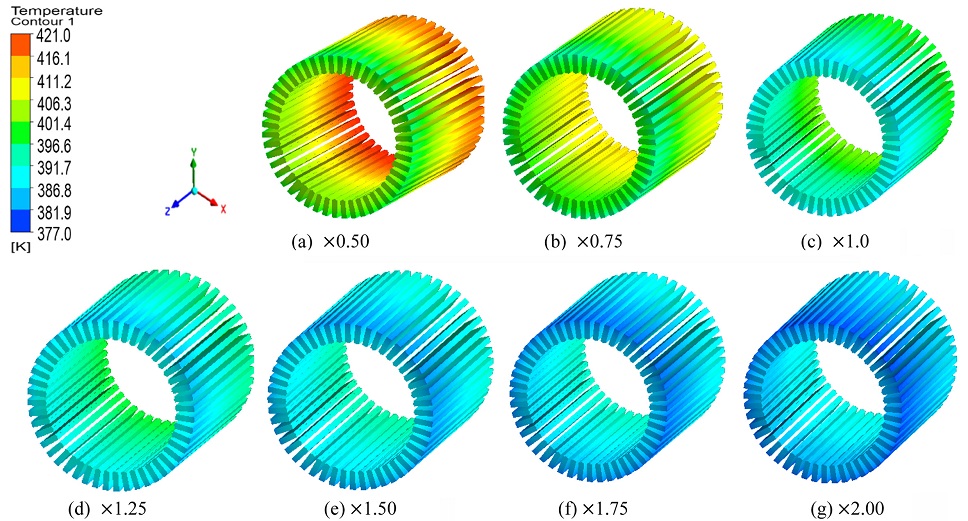
Fig. 17은
Table 7에서 제시한 7개의 질량 유량에서의 코일의 온도 분포를 나타낸 그림이다. 질량 유량이 증가할수록 냉각 채널과 코일의 온도는 감소하였으며 7개의 질량 유량에서 냉각 채널의 최고온도는 0.5배(117
oC), 0.75배(108
oC), 1배(97
oC), 1.25배(93
oC), 1.5배(90
oC), 1.75배(87
oC), 2배(84
oC)로 나타났다.
Fig. 17Coil temperature contours by mass flow rate of ethylene glycol

냉각 채널에서의 질량 유량이 증가할수록 냉각 채널의 최고온도는 감소하지만 온도가 감소하는 비율은 점점 낮아지는 것을 알 수 있다. 코일의 최저온도와 최고온도는 0.5배(122.25, 147.05oC), 0.75배(120.15, 139.15oC), 1배(112.45, 129.25oC), 1.25배(110.65, 125.25oC), 1.5배(108.55, 121.25oC), 1.75배(106.85, 119.15oC), 2배(105.85, 117.75oC)로 나타났다.
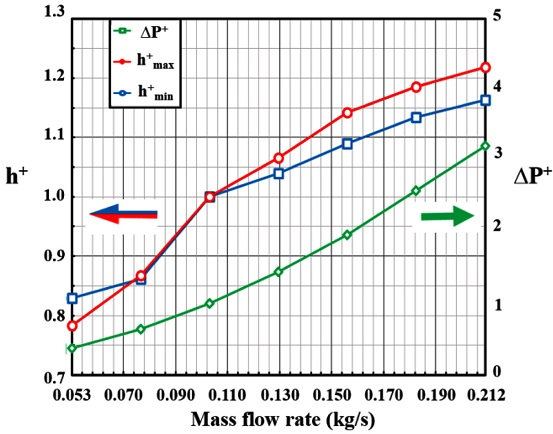
기존의 질량 유량 대비 다른 질량 유량의 냉각 성능을 정량적으로 비교하기 위하여 열전달 계수(h)를 해석하였다.
Fig. 18은 각각의 질량 유량에서의 코일의 최고온도와 최저온도가 나타난 지점의 열전달 계수(h)를 h
+로 무차원화하여 그래프로 나타낸 것이다. 또한 각각의 질량 유량에 대한 냉각 채널 내부에서의 압력 강하 정도를 ΔP
+로 무차원화하여 그래프로 나타내었다.
Fig. 18Dimensionless heat transfer coefficient and pressure drop vs. mass flow rate of ethylene glycol

식(3)에서의 h
o는 기존의 질량 유량(0.106 kg/s)에서 코일의 열전달 계수(h)이고, h
f는 변경한 질량 유량에서 코일의 열전달 계수(h)이다.
식(4)에서의 ΔP
o는 냉각 채널에서 기존의 질량 유량(0.106 kg/s)을 설정하였을 때 냉각 채널에서의 압력 강하(ΔP) 값이고, ΔP
f는 변경한 질량 유량에서 냉각 채널의 압력 강하(ΔP) 값이다.
Fig. 18의 청색선(h
+min)은 각각의 질량 유량에 대한 코일의 표면에서 최저온도가 나타난 지점의 열전달 계수(h)를 무차원화한 것이고, 적색선(h
+max)은 질량 유량에 대한 코일의 표면에서 최고온도가 나타난 지점의 열전달 계수(h)를 무차원화한 것이며, 녹색선(ΔP
+)은 질량 유량에 대한 냉각 채널의 내부 압력 강하(ΔP)를 무차원화하여 나타낸 것이다.
Fig. 18에서 h
+는 왼쪽 세로축을 기준, ΔP
+는 오른쪽 세로축을 기준으로 한다.
Fig. 18의 그래프를 보면 질량 유량이 증가할수록 열전달 계수(h)와 압력 강하(ΔP) 모두 증가하는 것을 알 수 있다. 기존 질량 유량의 0.5배(0.053 kg/s), 0.75배(0.0795 kg/s) 하였을때 h
+와 ΔP
+값이 1보다 작은 값을 가짐으로 기존의 질량 유량보다 냉각 성능이 떨어지고, 압력 강하는 감소하는 것을 알 수 있다. 질량 유량을 1.25배(0.1325 kg/s), 1.5배(0.159 kg/s), 1.75배(0.1855 kg/s), 2배(0.212 kg/s) 하였을 때는 h
+와 ΔP
+값이 1보다 크게 나타남으로 냉각 성능과 압력 강하 모두 증가하는 것을 알 수 있다. h
+와 ΔP
+를 기존의 질량 유량에서의 값을 기준으로 비교하여 보면 질량 유량을 1.25배로 설정하였을 때 코일에서의 최저온도는 1.6% 감소하고, 최고온도는 3.1% 감소하였다. 질량 유량을 1.5배하였을 때 최저온도 3.5%, 최고온도 6.2%, 1.75배 하였을 때 최저온도 5.0%, 최고온도 7.8%, 2배 하였을 때는 최저온도 5.7%, 최고온도 8.9% 정도 감소하여 질량 유량이 증가할수록 냉각 성능이 향상되었지만 질량 유량이 증가할수록 냉각 성능이 향상되는 비율은 감소하였다. 압력 강하는 질량 유량을 1.25배로 설정하였을 때 44.7% 증가하였고, 1.5배 하였을 때 96.8%, 1.75배하였을 때 158.7%, 2배 하였을 때 221.8% 정도 증가하였다. 질량 유량이 증가하면 냉각 성능과 압력 강하 모두 증가하게 되지만 냉각 성능이 증가하는 비율에 비해 압력 강하(ΔP)가 증가하는 비율이 상당히 높은 것을 알 수 있다. 압력 강하가 증가하게 되면 전기자동차 모터 외부에 존재하는 펌프에서 더 많은 동력을 소모하여 냉각 채널에 냉각수를 투입하게 된다. 전기자동차 배터리의 전기에너지를 모터에서 기계에너지로 변환하여야 하는데 높은 질량 유량으로 인해 압력 강하가 증가하여 펌프에서 많은 동력을 소모하게 되면 전기자동차 전체적인 효율이 감소하게 된다. 따라서 비교적 압력 강하 비율이 적은 질량 유량인 1.25-1.5배(0.1325-0.159 kg/s) 내외가 최적의 질량 유량으로 판단되어 8-10 LPM에서 전기자동차 모터에 들어가는 최적의 유량을 선정하는 것이 바람직하다고 판단한다.
3.4 열변형 FSI 해석
코일의 경우 일정 온도 이상이 되면 열변형을 동반하여 소손이 발생하게 되며, 이에 따라 코일의 기능을 상실하게 되어 모터가 제기능을 발휘하지 못하게 된다. 또한 모터 내부 코일의 열변형이 내부 회전자 쪽으로 발생하게 되면 고정자와 회전자 사이의 공극(회전자와 고정자 사이의 공기로 이루어진 간극)을 침범하게 되어 모터의 출력에 큰 영향을 미치게 될 것이다. 회전자와 고정자 사이의 간극은 모터 출력에 있어 중요한 인자이다. 공극은 0.7-1.0 mm 사이로 매우 작은 간극을 형성하고 있어 코일의 작은 열변형으로도 문제가 발생할 수 있기 때문에 코일의 변형 정도는 모터 설계에 있어서 중요한 인자이다.
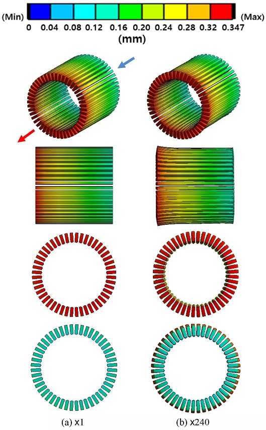
Fig. 19는 냉각 성능이 가장 우수하게 나타난 방열핀이 2개 부착된 냉각 채널을 탑재한 모터에서 기존의 질량 유량(0.106 kg/s)을 설정하고, ANSYS FLUENT V20.2로 얻은 Data를 ANSYS MECHANICAL V20.2와 연동하여 FSI 해석기법을 통해 얻은 모터 내부 코일에서의 열변형을 그림으로 나타낸 것이다.
Figs. 19(a)는 실제 열변형 정도를 그림으로 나타낸 것이고,
19(b)는 열변형의 형태와 방향을 한눈에 파악하기 쉽게 실제 열변형 정도에 240배 증가시킨 그림이다.
Fig. 19에 나와있는 코일의 왼쪽 붉은 영역이 냉각 채널의 출구와 인접한 부분이다. 냉각 채널의 입구와 가장 인접한 코일에서 열변형이 가장 적게 발생하였고, 냉각 채널의 출구와 가장 인접한 부분에서 열변형이 가장 많이 발생하였다. 코일에서의 열변형 범위는 0.097-0.347 mm로 나타났으며 코일의 길이 방향의 전체 길이는 175 mm로 길이 방향 전체 길이를 기준으로 열변형은 0.055-0.198% 정도 발생하였다.
Fig. 19Thermal deformation contours of coil at case 3

4. 결론
본 연구는 현재 출시 되어있는 K사의 모델 N의 전기자동차 모터를 분해 후 실측하여 모터 하우징, 코일, 고정자, 회전자, 영구 자석, 동력 전달 축은 동일하게 설계하였고, 냉각 채널의 형상은 변경하여 방열핀이 부착되지 않은 냉각 채널과 방열핀이 1, 2개 부착되는 냉각 채널을 설계하여 방열핀 부착에 따른 냉각 성능을 냉각 채널 내부 냉각수의 속도 분포와 냉각 채널의 온도 분포, 코일의 온도 분포를 비교하여 냉각 성능이 가장 우수한 냉각 채널을 찾는 거에 초점을 두고 연구를 수행하였다. 코일에서 냉각 성능이 취약하고, 온도 분포의 편차가 가장 큰 표면의 열전달 계수(h)를 해석하여 방열핀 부착에 따른 냉각 채널에서의 강제 대류 열전달에 의한 모터 내부의 냉각 성능을 비교하기 위하여 Nusselt 수를 계산하여 분석하였다. 또한 FSI 해석기법을 통한 코일에서의 열변형 정도를 구하였고, 냉각 채널과 코일의 온도, 냉각 채널 내부의 압력 강하를 고려하여 최적의 질량 유량을 선정하였다. 이에 따른 연구의 결론은 다음과 같이 정리하였다.
(1) 3가지 Cases 모두 입구에서 동일한 질량 유량에 대한 냉각 채널 내부 냉각수의 평균속도는 방열핀이 2개 부착된 Case 3에서 가장 빠르게 나타났다. Cases 3의 평균속도는 1에 비해 17.4%, 2에 비해 8.6% 빠르게 나타났다.
(2) 냉각 채널의 온도는 냉각수의 평균속도가 가장 빠른 Case 3에서 가장 낮게 나타났다. 냉각 채널의 최고온도는 Cases 3이 1에 비해 5.4%, 2에 비해 1.1% 낮게 나타났다.
(3) 방열핀 부착에 따른 냉각 채널에서의 강제 대류를 통해 코일의 온도 분포를 비교해본 결과 Case 3에서 코일의 최고온도와 최저온도가 가장 낮게 나타났다. Case 1에 비해 최고온도 4.7%, 최저온도 6% 낮게 나타났고, Case 2에 비해서는 최고온도 1.7%, 최저온도 1.7% 정도 낮게 나타났다.
(4) 3가지 Cases 모두 코일에서 온도 분포의 편차는 옆면에서 대각선 방향으로 가장 크게 나타났으며 냉각 채널의 입구와 가장 가까운 코일 표면(R+ = 0)에서 출구와 가장 가까운 코일 표면(R+ = 1)으로 갈수록 온도가 증가하여 냉각 성능이 떨어지는 것을 알 수 있었다. 냉각 성능이 가장 우수한 코일 표면(R+ = 0)과 냉각 성능이 가장 취약한 코일 표면(R+ = 1)의 온도 편차는 Cases 1에서 16.02oC, 2에서 17.09oC, 3에서 16.81oC로 나타났다.
(5) 냉각 채널 내부의 압력 강하와 온도 분포, 코일의 온도 분포를 7개의 질량 유량을 통해 비교해본 결과 기존 질량 유량의 1.25배에서 1.5배 사이의 유량이 최적의 질량 유량이라고 판단되어 8-10 LPM이 전기자동차 모터에서 필요로 하는 최적의 유량으로 판단한다.
(6) 전기자동차 모터 내부 코일에서의 열변형은 냉각 채널의 출구에 인접할수록 많이 발생하였으며 코일의 길이 방향 전체 길이를 기준으로 열변형은 0.055-0.198% 정도 발생하였다.
(7) 이번 연구에서 방열핀 부착에 따른 냉각 성능을 비교해본 결과 냉각 채널에 방열핀이 2개 부착된 냉각 채널의 냉각 성능이 가장 우수하다고 판단한다. 방열핀이 2개 부착된 냉각 채널이 방열핀이 부착되지 않은 냉각 채널과 방열핀이 1개 부착된 냉각 채널보다 생산 공정에서 비교적 복잡할 수 있지만 실제 생산하는데 있어서 큰 문제는 없는 것으로 판단되어 실제 전기자동차 모터의 냉각 채널에 방열핀이 2개 부착된 냉각 채널을 문제없이 사용할 수 있다고 판단한다.
(8) 최종적으로 냉각 채널에 방열핀이 2개 부착된 모터를 사용하는 것이 냉각 성능이 가장 우수하고 최적의 유량은 8-10 LPM으로 판단된다. 본 연구에서 냉각 성능이 가장 좋은 방열핀을 2개 부착한 냉각 채널을 기준으로 추후에는 모터 전체 부품에서의 열변형 정도와 열변형이 가장 적게 일어나는 최적 설계, 냉각 방식으로는 기존의 수냉에서 공냉을 추가, 코일의 외부에 접촉하고 있는 회전자의 소재를 열전도성이 좋은 그래파이트 등 첨단 소재로 변경 등 다양한 접근을 통해 모터의 냉각 성능과 효율을 더욱 향상시킬 것이다.
ACKNOWLEDGMENTS
이 결과물은 2021년도 대구가톨릭대학교 학술연구비 지원에 의한 것임.
REFERENCES
- 1.
Jin, C. S., “Estimation of Permanent Magnet Temperature of Permanent Magnet Motor,” Proc. of the Conference on the Korean Institute of Electrical Engineers, pp. 633-634, 2013.
- 2.
Lee, N. K., “Electric Motor Rotor Design to Improve Cooling Effect,” Proc. of the Spring Conference on the Korean Society of Automotive Engineers, pp. 1157-1158, 2017.
- 3.
Yoo, Y. B., Kim, T. H., Park, C. B., and Moon, S. J., “The Thermal Characteristics of 210 kW IPMSM during the Water Cooling Jacket based on Finite Element Method,” Proc. of the KSME Annual Conference, pp. 117-118, 2014.
- 4.
Lee, D. R., “Investigation of Cooling Performance of the Driving Motor Utilizing Heat Pipe,” Journal of the Korea Society for Power System Engineering, Vol. 10, No. 4, pp. 11-16, 2006.
- 5.
Choi, H. J., “A Study on the Design Factor Analysis of Water Jacket for Improving the Cooling Performance of Motor,” M.Sc. Thesis, Konkuk University, 2021.
- 6.
Kim, J. S., Moon, J. W., Kwak, T. H., and Kang, T. G., “Numerical Investigation on an Oil Cooling System in the Motor for a Hybrid Vehicle,” Journal of Computational Fluids Engineering, Vol. 22, No. 3, pp. 86-94, 2017.
10.6112/kscfe.2017.22.3.086
- 7.
Seo, J. and Cho, C., “Study on the Change of Cooling Performance of Motor Housing for Automobile,” Proc. of the KSME Annual Conference, pp. 2170-2174, 2012.
- 8.
Kang, Y. and Kim, D. K., “Comparative Study of Cooling Methods of Motor for Electric Vehicles,” Proc. of the KSME Annual Conference, p. 1646, 2019.
- 9.
Nam, G. G., Joo, W. G., Son, S. W., Kim, J, H., Park, J. Y., et al., “A Numerical Study on the Cooling Channel of Permanent Magnet Motor,” The Korean Society for Fluid Machinery Journal of Fluid Machinery, Vol. 23, No. 2, pp. 35-41, 2020.
10.5293/kfma.2020.23.2.035
- 10.
Lee, S. J., “A Study on the Thermal Characteristic according to the Cooling Jacket of High Speed Spindle by using FSI Method,” M.Sc. Thesis, Changwon National University, 2012.
- 11.
Tikadar, A., Johnston, D., Kumar, N., Joshi, Y., and Kumar, S., “Comparison of Electro-Thermal Performance of Advanced Cooling Techniques for Electric Vehicle Motors,” Applied Thermal Engineering, Vol. 183, Paper No. 116182, 2021.
10.1016/j.applthermaleng.2020.116182
Biography
- Si-Mok Park
B.S. candidate in the School of Mechanical and Automotive Engineering, Catholic University of Daegu. His research interest is electric vehicle and future alternative energy.
- Dong-Ryul Lee
Professor in the School of Mechanical and Automotive Engineering, Catholic University of Daegu. His research interest is heat transfer, fluid engineering, and electric vehicle.