ABSTRACT
In this study, a novel size adjustable robot that could overcome an unstructured environment was introduced. To provide the robot with a volume-modifiable function, negative Poisson’s ratio structure with a unique characteristic about deformation of material was applied to the design of the body frame. The robot could simultaneously adjust its width and length with only one directional control with the help of the negative Poisson’s ratio structure. An omni-directional mobile mechanism was adopted to drive its wheels and allow flexible movement in a narrow space. However, during the procedure to adjust the size of the robot, a slip phenomenon occurred, resulting in an unnecessary movement. To solve this problem, the unnecessary offset was measured through repetitive tests and applied to the robot to compensate the position shift. To verify the performance of the robot, a test bed with a narrow space was fabricated. Extensive experiments were conducted to evaluate environmental recognition and size adjustment function by calculating the width of the narrow space and scaling the robot's body. Results confirmed that the robot sufficiently achieved the motion objective to move in a narrow space with its size adjustment function.
-
KEYWORDS: Negative poisson’s ratio, Size adjustable robot, Mecanum wheel, Omni-directional mobile robot, Environmental recognition
-
KEYWORDS: 음의 포아송비, 크기 조절 로봇, 메카넘휠, 전방향 이동로봇, 환경 인식
1. 서론
최근 4차 산업혁명이 크게 활성화되며 다양한 로봇들이 인간을 대신하여 작업 현장에 투입되고 있다. 이러한 로봇들은 불확실성이 없는 정형화된 환경에서 임무를 정확하게 수행하며 그 효용성을 입증하였다. 최근에는 정형화된 환경을 벗어나 비정형화된 환경에서도 임무를 수행할 수 있는 로봇 시스템 개발에 관심이 커지고 있다. 여기서 비정형 환경이란 작업 대상의 크기와 형상이 일정하지 않거나 작업 공간에서 사람 혹은 구조물들이 자주 변화하여 단순 반복이나 간단한 절차로 구조화되기 어려운 환경을 의미한다.
1
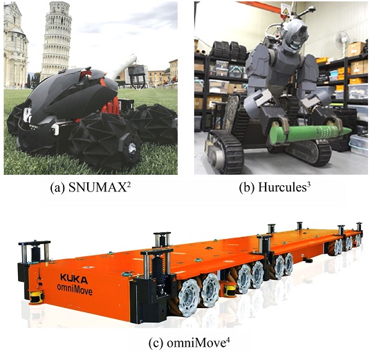
Fig. 1은 비정형 환경에 대응하기 위해 개발된 로봇 사례들을 보여준다.
Fig. 1(a)는 서울대학교 기계공학과 바이오로보틱스 연구실에서 개발한 SNUMAX이다.
2 이 로봇은 종이 접기식 구조로 설계된 바퀴의 부피 변형을 이용하여 좁은 통로 및 험지를 지나가거나 계단을 오를 수 있다.
Fig. 1(b)는 국방과학연구소에서 개발한 Hurcules이며, 복잡하고 위험한 환경에서 인간을 대신하여 부상자를 구조하고, 위험물을 처리하는 임무를 수행한다.
3 Fig. 1(c)는 독일 KUKA사에서 개발한 물류 이송로봇 omniMove이다.
4 이 물류 이송로봇은 자신보다 부피가 크거나 무거운 중량물 운반이 요구될 때 복수개의 로봇들이 군집한다.
Fig. 1 Robot examples developed for non-structured environment3-4 (Adapted from Refs. 2, 3, and 4 on the basis of OA)

로봇이 공장과 같은 정형화된 환경에서 벗어나 인간을 대신하여 임무를 수행하기 위해서는 환경이 주는 불확실성을 극복하고, 강건한 방법으로 임무를 수행할 수 있는 기술을 확보해야 한다. 본 연구에서는 작업 대상 및 공간이 동적으로 변하는 비정형 환경에 대응하기 위한 새로운 방법론으로써 로봇 본체의 부피 변형이 가능한 크기 조절 메커니즘을 제안하며, 개발한 크기 조절 이동로봇의 하드웨어 설계와 제어 전략에 대해 설명하고자 한다. 그리고 비정형 환경의 테스트 베드를 다양한 크기의 협소 통로로 구현하였고, 이를 크기 조절 메커니즘을 통해 극복하는 실험을 수행하여 크기 조절 이동로봇의 성능을 검증하고자 한다.
2. 크기 조절 로봇 본체 설계
2.1 음의 포아송비 구조
부피 변형이 가능한 로봇의 본체를 구현하기 위하여
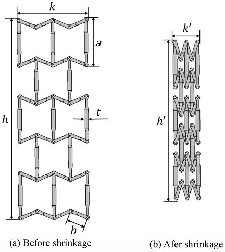
Fig. 2에 나타나 있는 음의 포아송비(Negative Poisson’s Ratio) 격자 구조를 본체 프레임(Body Frame) 설계에 적용하는 방법을 제안한다. 음의 포아송비 ν는
식(1)과 같이 가로 변형률
εlat과 세로의 변형률
εlong이 양의 관계에 있기 때문에 기존의 포아송비와는 다른 독특한 특성을 가진다. 일반적인 재료의 물성은 가로의 길이가 줄어들면 세로의 길이가 늘어나는 것이 일반적이다. 하지만 음의 포아송비를 가지는 물체는
Fig. 2에서 보여주는 바와 같이 가로의 길이가 줄어들면 세로의 길이도 함께 줄어들고, 가로의 길이가 늘어날 때는 세로의 길이도 함께 늘어난다.
5-8
Fig. 2Structure of a body with negative Poisson’s ratio

음의 포아송비를 갖는 구조에 대한 사전 테스트를 진행하기 위하여 CATIA 3D 설계 프로그램을 이용하여 축소 시뮬레이션을 진행하였다.
Fig. 2(a)에서
a와
b는 음의 포아송비 격자 구조를 이루고 있는 링크들의 길이를 나타낸다. 축소 시뮬레이션은 링크 길이
a를 100 mm로 고정하고, 링크 길이
b를 변화시켜가며 크기 축소 전후로 본체 프레임의 전체 너비
k와 길이
h의 변화를 확인하였다.
Tables 1과
2는 축소 시뮬레이션의 결과를 각각 나타낸다. 이를 통해 링크 길이
a와
b의 비율을 1 : 0.45로 하였을 때, 본체 프레임 전체 너비가 62.8%로 절반 이상 줄어들고 전체 길이가 20.6% 줄어들어 가장 높은 크기 축소 효과가 있다는 것을 알 수 있다.
Table 1
Simulation results of the width shrinkage
(Unit: mm)
Table 1
|
a
|
t
|
b
|
a : b
|
k
|
k' |
Ratio [%] |
|
100 |
8 |
30 |
1 : 0.3 |
82 |
66 |
19.5 |
|
35 |
1 : 0.35 |
98.2 |
76 |
22.6 |
|
40 |
1 : 0.4 |
116 |
66 |
43.1 |
|
45 |
1 : 0.45 |
145 |
54 |
62.8 |
|
50 |
1 : 0.5 |
168 |
86 |
48.8 |
Table 2
Simulation results of the length shrinkage
(Unit: mm)
Table 2
|
a
|
t
|
b
|
a : b
|
h
|
h' |
Ratio [%] |
|
100 |
8 |
30 |
1 : 0.3 |
428.06 |
401.79 |
6.1 |
|
35 |
1 : 0.35 |
419.21 |
383.27 |
8.6 |
|
40 |
1 : 0.4 |
415.89 |
350.33 |
13.7 |
|
45 |
1 : 0.45 |
412.01 |
327.33 |
20.6 |
|
50 |
1 : 0.5 |
408.78 |
315.68 |
22.8 |
2.2 음의 포아송비 구조를 활용한 로봇 본체 설계
음의 포아송비 격자 구조로 이루어진 로봇의 본체를 구현하기 위하여
Fig. 3과 같이 설계하였다. 총 8가지 종류의 링크 부품들을 설계하였고, 다수의 링크들을 조인트로 체결하는 방식을 택하였다.
Figs. 3(a)는 크기 조절 로봇의 상부 본체 프레임이고,
3(b)는 하부 본체 프레임이다. 두 가지 종류의 본체 프레임은
Fig. 4(a)와 같이 길이 방향 양쪽 측면에서 프레임 쉴드(Frame Shield)와 결합된다. 본체 프레임을 상부와 하부로 구성된 2단 구조로 사용하는 이유는 1개의 본체 프레임만을 사용할 경우 로봇을 지면에 놓았을 때 자중과 조인트 유격으로 인하여 로봇 본체의 가운데 부분에 처짐 현상이 발생하기 때문이다. 그래서 2단 구조 설계를 통하여 본체 프레임과 프레임 쉴드의 접촉 면적을 넓혀, 자중과 조인트 유격으로 인한 처짐을 최소화하였다.
Fig. 3Design of the body frame
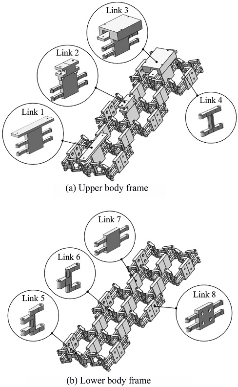
Fig. 4Robot body assembly
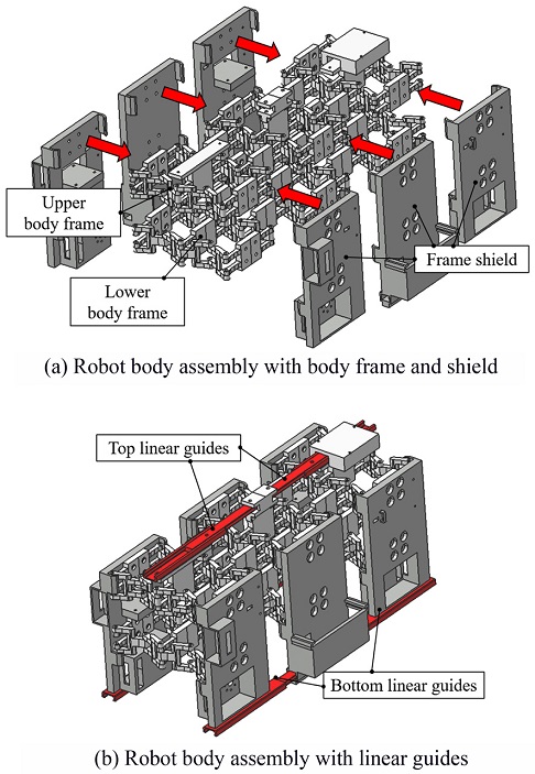
다수의 링크 결합 방식으로 설계된 본체 프레임의 특성상 모든 링크들의 절점이 독립적인 자유도를 갖게 된다. 이로 인해 크기 조절 로봇의 본체가 일정한 형상을 유지할 수 없기 때문에 로봇이 크기 조절과 이동을 정상적으로 수행할 수 없다. 상승된 자유도를 구속하기 위해
Fig. 4(b)와 같이 로봇 본체에 리니어 가이드(Linear Guide)를 설치하였다. 리니어 가이드의 부착 위치는 상부 본체 프레임에 2개, 좌우 측면의 프레임 쉴드 하단에 2개씩 설치하였다. 길이 방향 움직임만을 허용하는 리니어 가이드를 설치함으로써 크기 조절 로봇 본체의 길이 방향으로는 1 자유도 운동만을 허용하였다. 그리고 리니어 서보 모터를 가로 방향으로 설치하여 로봇 본체의 너비 방향 움직임을 통제하였다. 결과적으로 로봇 본체는 총 2자유도를 가지고, 프레임 쉴드와 리니어 가이드가 로봇 본체의 여러 링크를 유기적으로 연결하여 한 방향의 크기 조절 액추에이션만으로 로봇 본체의 너비와 길이를 동시에 조절할 수 있다.
3. 전방향 이동 메커니즘
크기를 조절해 협소한 공간에 진입한 후 로봇은 자유롭게 방향을 전환하여 유연하게 이동할 수 있어야 한다. 일반 바퀴는 구동축의 회전이 전후진 방향의 힘 성분만 만들기 때문에 방향을 전환하기 위해서는 조향 장치가 필요하다. 일반 바퀴를 장착한 로봇은
Fig. 5(a)와 같이 협소 공간 내에서 방향 전환이 필요할 경우 로봇의 회전 반경만큼의 공간이 필요하기 때문에 이동이 어렵다. 그러나 전방향 이동이 가능한 메카넘휠을 로봇의 바퀴로 사용하면 즉각적으로 이동 방향을 전환할 수 있어서 위와 같은 어려움을 극복할 수 있다.
Fig. 5(b)는 메카넘휠을 장착한 로봇이 즉시 이동 방향을 전환해 좁은 통로에서 원활하게 이동하는 모습이다.
Fig. 5 Comparison between differential drive and omni-directional drive
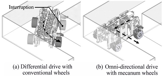
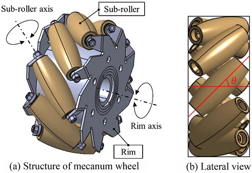
Fig. 6(a)는 전방향(Omni-Directional) 이동 방식의 메카넘휠이 가지는 독특한 구조를 보여준다. 메카넘휠은 다수 개의 서브롤러(Sub-Roller)와 이들을 고정하는 림(Rim)으로 구성되어 있다. 모터의 회전축과 연결된 림을 회전시키면,
Fig. 6(b)와 같이
θ만큼 기울어진 서브롤러의 축 방향으로 지면 반력이 발생한다.
9,10 이동로봇은 각 메카넘휠에서 발생하는 반력 성분들의 총 합력 방향으로 이동한다. 이 연구에서 사용한 메카넘휠은 10개의 서브롤러들이 45
o 각도로 장착되어 있다.
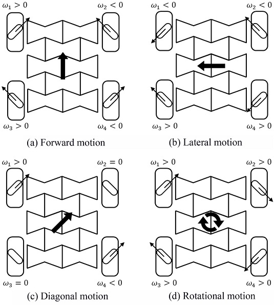
Fig. 7과 같이 메카넘휠과 연결된 모터의 회전 속도
ωi(
i = 1, 2, 3, 4)를 제어하면 전후좌우 및 대각 이동뿐만 아니라 제자리 회전도 가능하다.
Fig. 7(a)와 같이 로봇 좌측면에 설치된 모터들의 회전 속도
ω1과
ω3을 반시계 방향으로 회전시키고, 로봇 우측면에 설치된 모터들의 회전 속도
ω2과
ω4를 시계 방향으로 회전시키면, 각 바퀴에서 발생한 4개의 반력 성분들이 더해지며 좌우 방향의 힘 성분은 상쇄되고, 전진 방향의 힘 성분만 남아 로봇은 전진한다. 그리고
Fig. 7(b)에 나타나 있는 방향으로 모터들을 회전시키면 각 메카넘휠에서 발생하는 지면 반력 성분들을 합하였을 때, 전후 방향의 힘 성분은 상쇄되고, 좌측 방향의 힘 성분만 남아 로봇은 좌측으로 이동한다.
Fig. 7(c)와 같이 로봇 좌측면 앞 쪽에 설치된 모터와 로봇 우측면 뒤 쪽에 설치된 모터를 각각 반대 방향으로 회전시키면, 두 바퀴에서 발생하는 지면 반력 성분들의 합이 대각선 방향으로 발생하는 것을 확인할 수 있다. 반면 나머지 두 바퀴에 설치된 모터를 정지시키면 림 주변의 서브롤러로 구성된 메카넘휠의 지면과 맞닿은 서브롤러가 수동적으로 회전하며 미끄러지기 때문에 2개의 바퀴만을 사용해 대각선 방향으로 이동할 수 있다.
Fig. 7(d)와 같이 모든 메카넘휠들을 같은 방향으로 회전시키면 로봇은 제자리에서 회전 동작을 수행할 수 있다. 이렇게 높은 이동성을 가지는 메카넘휠이 크기 조절 메커니즘과 접목되면 자신보다 협소한 공간에 진입할 수 있을 뿐만 아니라 협소 공간 내에서도 자유롭게 이동할 수 있다.
11,12
Fig. 6 Mecanum wheel

Fig. 7 Moving mechanism of omni-directional mobi1ity
4. 크기 조절 로봇 시스템 구성 및 제어
4.1 로봇 하드웨어 설계
Fig. 8은 본 연구에서 제안하는 크기 조절 로봇의 실제 모습을 보여준다. 그리고
Fig. 9는 크기 조절 로봇의 하드웨어 구성과 신호 흐름을 설명한다. 크기 조절 로봇상에 설치된 와이파이(ESP8266) 및 블루투스 모듈(HC-06)은 사용자의 스마트폰과 무선 연결된다. 사용자는 스마트폰에 설치된 유저 인터페이스 앱을 통해 로봇에게 동작 신호를 입력하거나 카메라 센서(OV2640)의 시각 데이터를 전송받아 로봇의 전방 상황을 실시간으로 모니터링할 수 있다. 사용자에 의해 입력된 명령 신호는 메인 컨트롤러(Arduino Mega)를 통해 구동 모터(Dynamixel MX-64R)에 전달되어 각각의 메카넘휠들을 독립적으로 구동시킨다. 그리고 사용자가 로봇에게 크기 조절 명령을 입력하면 리니어 모터(L12-30T-10)가 동작하며 로봇 본체의 크기를 조절한다.
Fig. 8Actual view of the size adjustable robot
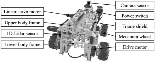
Fig. 9Hardware design
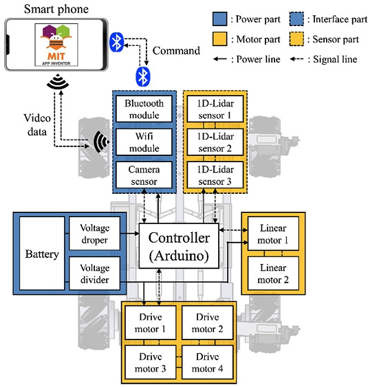
Table 3Specification of the size adjustable robot components
Table 3
|
Component |
Model |
Specification |
|
Main controller |
Arduino MEGA |
Analog & Digital I/O Serial communication |
|
Camera module |
ESP8266 Arduino UNO |
Built-in ESO8266-12F & SD card slot |
|
Bluetooth module |
HC-06 |
Detect range [mm]: 200-1,500 |
|
1D-Lidar sensor |
LIDER-Lite V4 LED |
Detect distance [mm]: 50-10,000 |
|
Camera sensor |
OV2640 |
Input voltage [V]: 3.3/5 Support JPEG |
|
Drive motor |
Dynamixel MX-64R |
Input voltage [V]: 12
Stall current [A]: 4.1
Stall torque [N]: 6 |
|
Linear motor |
L12-30PT-10 |
Input voltage [V]: 12
Rated output [N]: 31 |
4.2 환경 인식 및 제어 알고리즘
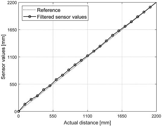
사용자가 스마트폰의 인터페이스를 통해 로봇 전방 상황을 실시간으로 모니터링하며 로봇을 수동으로 운전하다보면, 육안으로 통과 가능 여부를 판단하기 힘든 협소한 공간을 마주하는 순간이 있다. 이때 사용자는 크기 조절 로봇에게 환경 인식 기능을 시작하도록 명령한다. 환경 인식 기능을 시작한 로봇은 스스로 협소 공간 진입로의 폭을 계산하고 통과 가능 여부를 판단한 뒤, 로봇 본체 크기를 조절하여 협소 공간에 진입한다. 환경 인식 기능은 로봇에 설치된 레이저 센서(Lidar-Lite V4)를 사용한다.
Fig. 10은 레이저 센서의 성능 테스트 결과이며 레이저 센서의 위치를 점점 멀리하며 수집한 데이터를 그래프로 나타내었다. 본 연구에서 사용한 레이저 센서는 2,200 mm까지 20 mm 정도의 측정 오차를 보이며 1%의 오차율을 가진다는 것을 확인하였다. 크기 조절 로봇의 성능을 검증하기 위해 구성한 테스트 베드의 규격이 최대 2,200 mm이기 때문에 이 레이저 센서는 크기 조절 로봇의 성능 실험에 사용하기 적합하다고 판단한다.
Fig. 10Results of validation experiments of the 1D-Lidar sensor
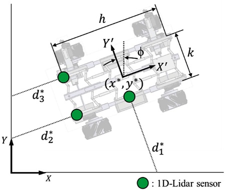
레이저 센서는
Fig. 11과 같이 로봇 본체 전면부의 양 옆에 2개, 좌측면의 중앙에 1개가 설치되어 있다. 크기 조절 로봇의 성능 실험을 위한 테스트 베드는 인위적으로 설치한 인공벽으로 구성된다. 환경 인식 기능을 수행하기 위해 로봇은
Fig. 12와 같이 벽으로부터 로봇까지의 거리
di*i=1,2,3를 레이저 센서를 이용하여 측정한다. 측정된 벽과의 거리와 크기 조절 로봇의 전체 너비
k 및 길이
h 정보를 기반으로
식(2)를 이용하면 크기 조절 로봇의 비틀림 각도
ϕ를 계산할 수 있다. 계산된 비틀림 각도와 레이저 센서 측정값을
식(3)에 대입하면 크기 조절 로봇의 중심 좌표(
x*,
y*)를 계산할 수 있다.
Fig. 11Distance measurement using 1D-Lidar sensors
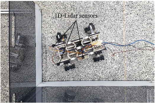
Fig. 12Distance measurement using 1D-Lidar sensors
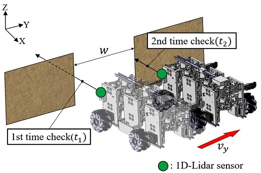
크기 조절 로봇은 환경 인식 기능을 통해 협소 공간 진입로의 폭
w를
Fig. 13과 같이 계산한다. 메카넘휠의 전방향 이동 메커니즘을 통해 로봇은 즉각적인 횡방향 이동을 하며 진입로의 폭을 스캔한다. 이때 로봇은 전방에 부착된 레이저 센서의 거리 측정값이 급격히 높아지는 순간 첫 번째 시간
t1을 저장하고, 거리 측정값이 다시 낮아지는 순간 두 번째 시간
t2을 저장한다. 저장된 시간값들과 크기 조절 로봇의 횡방향 이동 속도
vy를
식(4)에 대입하면 협소 공간 진입로의 폭을 계산할 수 있다. 크기 조절 로봇의 횡방향 이동 속도는 메카넘휠의 반경
R, 각 메카넘휠들의 회전 속도, 그리고 로봇의 너비 및 길이 정보를 이동로봇의 순기구학 방정식인
식(5)에 대입하여 계산할 수 있다. 그리고
식(6)은 이동로봇의 역기구학 방정식을 보여준다.
Fig. 13Scanning the width of the entrance using a 1D-Lidar sensor

크기 조절 로봇은 스캔 동작을 하기 전, 협소 공간 진입로의 스캔 오차를 줄이기 위해 인공벽을 기준으로 평형 상태를 맞춰야 한다. 그래서 현재 로봇의 비틀림 각도를 계산하고 비틀림 각도가 0에 수렴할 때까지 제자리 회전이 필요하다.
5. 크기 조절 로봇의 성능 실험
5.1 크기 조절에 의한 로봇 중심점 이동 보상 실험
림휠과 서브롤러로 구성되는 메카넘휠에 기반을 둔 전방향 이동로봇의 경우 바퀴의 구조적 특성상 전방향 이동이 가능하지만, 전방향성 이동 구현 과정에서 불필요한 슬립(Slip) 현상이 발생할 수 있다. 이동로봇이 전후 방향으로 이동할 경우 메카넘휠에는 림휠의 구름만 발생하여 비교적 슬립이 적은 반면, 이동로봇이 좌우 방향으로 이동할 경우 림휠보다는 서브롤러의 회전과 슬립 현상의 영향을 많이 받는다. 슬립은 대표적인 비시스템적(Non-Systematic) 요인으로서, 슬립을 발생시키는 요인을 찾아 최대한 줄여주는 것이 필요하다. 슬립이 발생하는 요인 중 하나는 4개의 바퀴에 작용하는 힘이 고르게 분산되지 않아 각 바퀴에서 발생하는 지면 반력이 어느 한쪽으로 쏠리게 되면서 비대칭 구조를 이루기 때문이다. 따라서 슬립 현상을 최소화하기 위해서는 4개의 바퀴가 지면과 균등하게 접지되어 각 바퀴에 균일한 분력이 분산될 수 있도록 해주는 서스펜션과 같은 부가 장치를 요구한다.
13
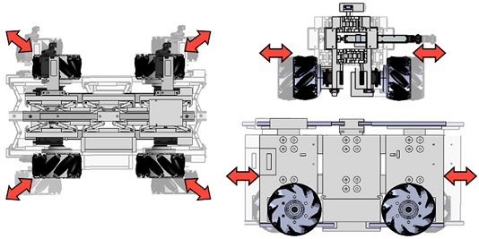
본 연구에서 다루고 있는 크기 조절 이동로봇이 크기 조절 기능을 수행하는 중에는 구동 모터가 정지 상태를 유지하고,
Fig. 14와 같이 오직 서브롤러의 회전만으로 로봇 본체 프레임의 각 모서리 부분이 로봇의 중심 방향으로 이동한다. 이 과정에서 슬립 현상으로 인한 로봇의 불필요한 이동이 발생한다. 이러한 로봇의 불필요한 이동은 로봇이 자신보다 협소한 공간에 크기 조절을 통해 진입하는데 있어서 진입 성공률을 낮춘다. 따라서 협소 공간 진입 성공률을 높이기 위해서는 서스펜션과 같은 부가 장치를 설치하여 슬립 현상을 최소화하는 방안이 있지만, 이 연구에서 개발된 크기 조절 이동로봇은 서스펜션과 같은 부가 장치를 설치할 만큼의 충분한 사이즈가 되지 않아 실험을 통해 크기 조절 전후로 로봇의 위치를 확인하여 슬립 현상의 경향성을 파악하고, 이를 보상하는 방향으로 로봇을 이동시키는 방법을 택하였다.
Fig. 14Three sides view of size adjustable mechanism

크기 조절 전후로 로봇의 슬립에 대한 경향성을 확인하기 위하여 반복 실험을 진행하였다. 로봇이 크기를 줄이기 전
Figs. 15(a)의 상태에서
12와 같이
x와
y 방향에 인공 벽을 설치하고, 로봇에 장착된 거리센서를 이용해 벽면으로부터의 거리 데이터
di*i=1,2,3을 일정 시간 동안 수집한다. 수집한 거리 데이터를
식(3)을 이용해 로봇의 중심 좌표 (
x*,
y*)로 변환한다. 그리고 리니어 모터를 구동시켜 로봇의 크기를 수축 한계(Shrinkage Limit)까지 줄인다. 수축 한계는 개발된 로봇을 구조적으로 안전하게 줄일 수 있도록 정한 최소 크기를 말한다. 다양한 구성 요소를 모두 탑재한 로봇은 로봇의 본체만을 고려하는 경우와는 달리 크기가 줄어들 때 모터 장착부나 배터리와 같은 다양한 간섭 요소를 피하기 위해 물리적 한계를 지정해야 한다. 본 연구에서 지정한 로봇의 수축 한계는 가로 284, 세로 331 mm이다. 로봇의 크기를 수축 한계까지 줄인 후
Fig. 15(b)의 상태에서 다시 한 번 일정 시간 동안 거리 데이터를 수집하고, 수집한 거리 데이터를 로봇의 중심 좌표로 변환한다. 이 과정을 10회 반복하였고, 그 결과를
Fig. 16(b)과
Table 4에 나타낸다.
Table 4의 Δ
x, Δ
y는
Fig. 16(a)에 표시한 각 축 방향으로의 위치 변화량을 의미하며, Δθ는 슬립이 진행된 방향을 나타낸다. 실험 결과 크기 조절 전후로의 슬립은 비슷한 경향성을 보였으며, 평균적으로
x축 방향으로 30.55,
y축 방향으로 28.76 mm 이동하였다. 로봇 제작 시 발생한 유격으로 인하여 4개의 바퀴에 균일한 분력이 분산되지 못하면서 로봇이 크기 조절 기능 수행 동안 4개의 바퀴가 로봇의 중심 방향으로 모이지 않고, 일정 방향으로 미끄러지는 결과를 보인다. 슬립은 비선형적 특성을 가지고 있지만, 각 바퀴에 작용되는 하중은 로봇에 무게를 추가하지 않는 한 일정하기 때문에 경향성을 가지는 것으로 판단한다. 따라서 평균 데이터를 이용하여 슬립 현상을 보상하는 방향을 결정하였다.
Fig. 15Actual view of the size adjustable robot before and after shrinkage
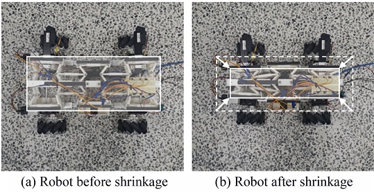
Fig. 16Center point movement before calibration
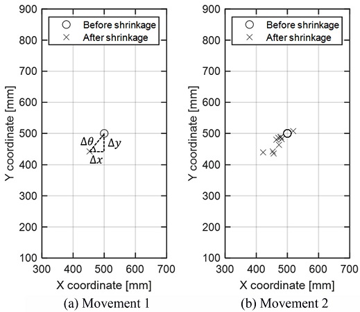
Table 4Result data of size control experiment without calibration
Table 4
Center point
movement |
Δx
[mm] |
Δy
[mm] |
Δθ
[deg] |
|
Maximum |
78.25 |
60.64 |
37.77 |
|
Minimum |
18.65 |
7.51 |
21.96 |
|
Average |
30.55 |
28.76 |
43.27 |
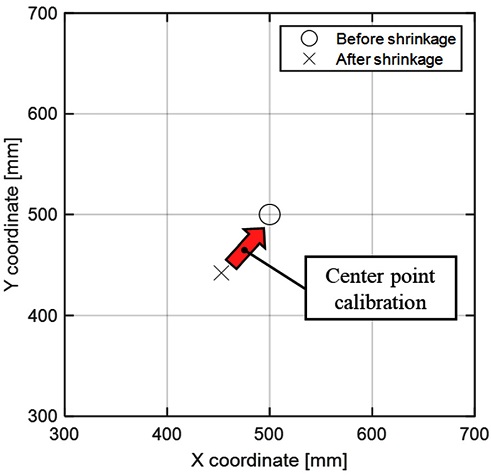
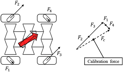
즉, 로봇은 크기 조절 중
Fig. 17과 같이 슬립 경향성에 반대되는 방향인 오른쪽 위를 향해 이동해야 한다. 로봇을 원하는 방향으로 이동시키기 위하여 실험 데이터를 기반으로
식(6)을 이용해 각 메카넘휠의 속도와 회전 방향을 계산하였다. 이를 통해 각 바퀴에 회전 속도를 제어하면
Fig. 18과 같이 각 바퀴들의 힘 성분
Fi(
i = 1, 2, 3, 4)이 더해져 로봇의 슬립을 보상하는 방향으로 이동할 수 있는 힘
Fc를 결정할 수 있다.
Fig. 17Center point movement calibration method

Fig. 18Calibration value for robot center point movement during shrinkage

위의 계산 결과를 바탕으로 로봇은 크기를 줄이는 시간 동안 메카넘휠을 회전시켜 슬립 현상을 줄일 수 있다.
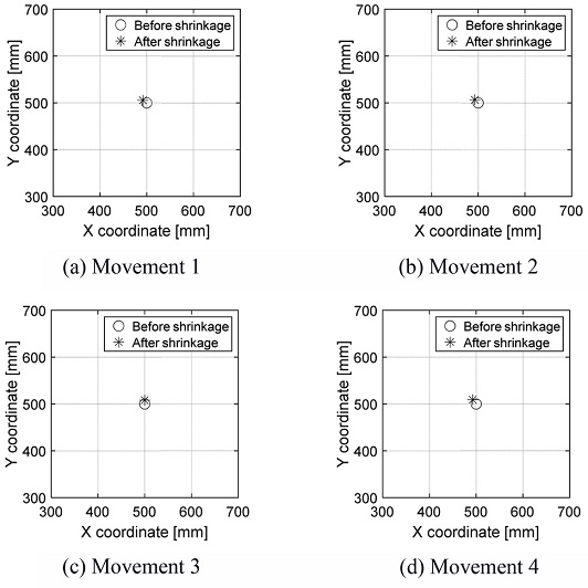
크기 조절 기능 수행 중 로봇의 불필요한 이동을 보상하는 방향으로 로봇을 이동시켰을 때, 슬립이 줄어들 수 있는지 확인하기 위한 검증 실험을 진행하였다. 실험은 앞선 실험과 동일한 방식으로 수행되었으며, 실험 결과를
Fig. 19와
Table 5에 나타낸다.
Fig. 19는 10개의 실험 결과 중 무작위의 4개의 결과를 나타낸 그래프이다.
Figs. 16과 비교했을 때 19는 중심점의 슬립 현상이 확연히 줄어든 모습을 볼 수 있다.
Table 5에서 슬립 현상 보상 이동을 적용한 후 중심점 이동량은 평균적으로
x 방향 5.11,
y 방향 8.88 mm이다. 이를 통해 서스펜션과 같은 부가적인 장치 없이 실험적으로 슬립 현상을 최소화할 수 있고, 환경 인식 기능을 활용한 협소 공간 진입 성공률을 높이는데 효과적임을 알 수 있다.
Fig. 19Center point movement after calibration

Table 5Result data of size control experiment with calibration
Table 5
Center point
movement |
Δx
[mm] |
Δy
[mm] |
Δθ
[deg] |
|
Maximum |
10.46 |
12.47 |
50.01 |
|
Minimum |
0.13 |
8.07 |
89.08 |
|
Average |
5.11 |
8.88 |
60.08 |
5.2 환경 인식을 통한 협소 공간 극복 실험
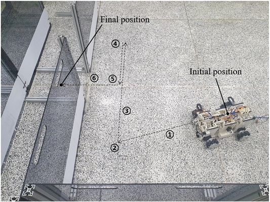
크기 조절 로봇이 이동 중 자신보다 협소한 공간을 만났을 때, 스스로 진입로의 폭을 인식하고 로봇 본체의 크기를 조절하여 극복하는 환경 인식 기능의 성능 평가 실험을 구성하였다. 협소 공간의 진입로를 테스트 베드로 구현하기 위하여
Fig. 20과 같이 인공벽을 세워두었다. 테스트 베드는 가로 2,200, 세로 2,200 mm이며, 로봇이 초기 위치(Initial Position)에서 환경 인식 기능을 시작하여 최종 위치(Final Position)까지 도달하는데 있어서 최종 위치의 진입로의 폭을 변화시켜가며 실험을 진행하였다.
Fig. 20Testbed of the environmental recognition experiment

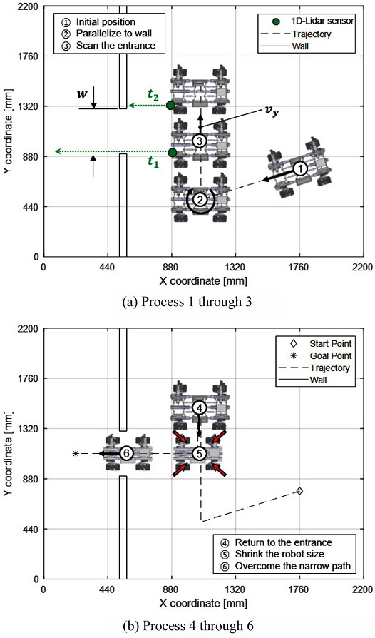
Fig. 20에 점선으로 표시된 환경 인식 기능 프로세스의 상세 내용은
Fig. 21에서 확인할 수 있다. 1) 실험을 시작하기 전, 크기 조절 로봇을 인공벽을 기준으로 어느 정도 기울인 상태로 배치한다. 크기 조절 로봇이 환경 인식 기능을 시작하면 로봇은 이동하면서 레이저 센서를 이용하여 테스트 베드 인공벽과의 거리를 측정한다. 2) 로봇이 이동 중 인공벽과의 거리가 가까워지면 인공벽을 기준으로 수평을 맞춘다. 3) 인공벽을 기준으로 수평 상태를 만든 로봇은 각 메카넘휠들의 지면 반력 성분들의 합이 우측을 향하도록 모터를 구동한다. 로봇은 우측 방향으로 이동하며, 협소 공간 진입로의 시작 지점과 끝 지점에서의 시간을 저장한다. 이를 통해 로봇이 진입로를 스캔하며 지나간 시간을 알 수 있고, 로봇의 횡방향 이동 속도와 곱하여 협소 공간 진입로의 폭을 계산할 수 있다. 4) 스캔 작업을 마친 로봇은 협소 공간 진입로의 중앙으로 돌아가기 위해 각 메카넘휠들의 지면 반력 성분의 합이 좌측을 향하도록 모터를 구동한다. 5) 진입로의 중앙 지점으로 돌아온 로봇은 계산된 진입로의 폭보다 작은 크기로 로봇의 본체를 축소한다. 6) 크기 축소를 마친 로봇은 협소 공간에 진입로를 향해 전진한다. 결과적으로 로봇은 자신보다 좁은 공간에 진입하여 최종 위치에 도달하게 된다.
Fig. 21Process of the environmental recognition experiment

환경 인식 기능을 평가하기 위해 테스트 베드에 세팅할 협소 공간 진입로의 폭은 크기 조절 로봇의 크기와 크기 조절 성능을 고려하여 결정되었다. 크기 조절 로봇의 전체 너비는 크기 축소 전 365이고, 크기 축소 후 284 mm이다. 그리고 앞서 진행한 예비 실험을 통해 크기 축소 전후로 슬립에 의해 발생하는 로봇 중심점의 이동을 확인하였다. 그리고 불필요한 중심점의 이동을 최소화하기 위해서 메카넘휠의 전방향 이동 메커니즘을 이용하여 보상하였다. 그 결과 로봇이 본체의 크기를 조절할 때 로봇 중심점이 y축 방향으로 불필요하게 이동하는 범위를 12 mm까지 줄일 수 있었다. 크기 조절 로봇이 안정적으로 협소 공간에 진입하기 위해서는 진입로의 폭이 크기 축소 후 로봇의 전체 너비보다 다소 여유가 있어야 한다. 그래서 테스트 베드에 설치될 협소 공간 진입로의 최대 폭을 385로 결정하였고, 최소 310 mm까지 15 mm씩 감소시키며 총 6가지 실험 환경을 구성하였다.
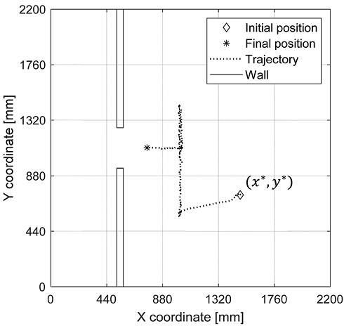
테스트 베드상에서 협소 공간 진입로의 폭을 325 mm로 세팅한 뒤, 환경 인식 기능 평가 실험을 진행하였다.
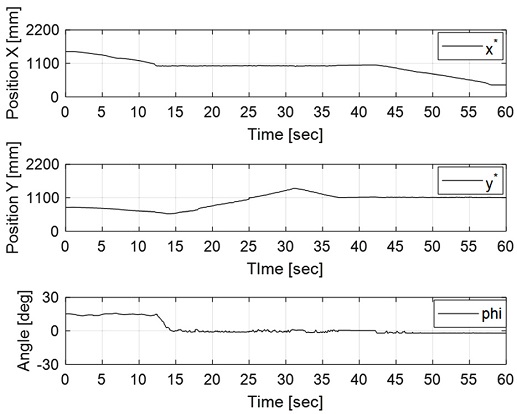
Fig. 22는 크기 조절 로봇이 초기 위치에서 최종 위치까지 실제로 이동한 경로를 그래프로 나타낸 것이다. 그래프상에서 로봇이 환경 인식 기능을 통해 협소한 진입로의 폭을 계산하고, 로봇 본체의 크기를 조절한 뒤 인공벽을 넘어 좁은 통로에 성공적으로 진입한 것을 확인할 수 있다. 크기 조절 로봇은 이동 중 로봇에 설치된 3개의 레이저 센서를 이용하여 인공벽까지의 거리를 측정한다. 센서 데이터를 기반으로 로봇의 중심 좌표(
x*,
y*)와 인공벽을 기준으로 로봇이 비틀린 각도
ϕ를 계산하여
Fig. 23에 그래프로 나타내었다.
ϕ 그래프상에서 크기 조절 로봇이 초기 위치에서는 비틀린 상태로 출발하였지만, 인공벽을 만난 이후부터는 평형 상태를 유지하는 것을 확인할 수 있다.
Fig. 22Trajectory of the size adjustable robot with environmental recognition when the width of the narrow path is 325 mm

Fig. 23Position and orientation of the size adjustable robot with environmental recognition when the width of the narrow path is 325 mm

Fig. 24는 테스트 베드에서 협소 공간 진입로의 폭을 310 mm로 세팅한 뒤, 환경 인식 기능 평가 실험을 진행한 결과를 보여준다.
Fig. 22와 비교하였을 때, 크기 조절 로봇이 크기 축소 후에도 협소 공간에 진입하지 못해 목표 위치에 도달하지 못한 것을 확인할 수 있다. 협소 공간 진입로의 폭이 310 mm일 때 로봇의 이동에 따른 중심 좌표의 변화와 인공벽을 기준으로 로봇의 비틀림 각도 변화를
Fig. 25에 나타낸다. 크기 조절 로봇이 일정 구간 이후부터
x 방향으로 전진하지 못하는 것을 제외하고는
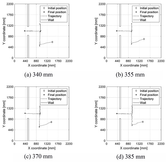
Fig. 23과 차이가 없는 것을 확인할 수 있다. 크기 축소 후 로봇의 전체 너비가 284이고, 현재 세팅된 협소 공간 진입로의 폭이 310 mm이므로 로봇이 통과하기에 26 mm 정도의 여유가 있다. 하지만 메카넘휠의 슬립 현상과 센서의 측정 오차로 인해 더 넓은 여유 너비가 필요한 것으로 판단된다. 그래서 크기 축소 후 로봇의 전체 너비 284 mm를 기준으로 협소 공간 진입로의 여유 너비를 26 mm보다 넓게 하면서 환경 인식 기능 평가 실험을 진행하였다. 각 실험 환경에서 환경 인식 기능을 통해 로봇이 이동하는 경로를
Fig. 26에 나타낸다. 모두 초기 위치에서 최종 목표 위치까지 문제없이 도달한 것을 그래프상에서 확인할 수 있다. 다양한 실험 환경에서 진행한 크기 조절 로봇의 환경 인식 기능 평가 실험의 결과를
Table 6에 나타내었다. 협소 공간 진입로의 폭이 310 mm인 경우를 제외한 모든 실험 조건에서 로봇이 환경 인식 기능을 통해 자신보다 좁은 공간에 진입할 수 있었다. 로봇의 크기 조절 예비 실험 및 환경 인식 기능 평가 실험에 대한 최종 결과를
Table 7에 나타낸다.
Fig. 24Trajectory of the size adjustable robot with environmental recognition when the width of the narrow path is 310 mm

Fig. 25Position and orientation of the size adjustable robot with environmental recognition when the width of the narrow path is 310 mm

Fig. 26Trajectories of the size adjustable robot with environmental recognition under various experimental conditions

Table 6Initial and final positions of the size adjustable robot
Table 6
Cases
[mm] |
x* [mm] |
y* [mm] |
ϕ [deg] |
Results |
|
Ini. |
Fin. |
Ini. |
Fin. |
Ini. |
Fin. |
|
310 |
1,491 |
760 |
728 |
1,101 |
14.62 |
-0.65 |
Fail |
|
325 |
1,485 |
391 |
778 |
1,105 |
15.20 |
-0.65 |
Success |
|
340 |
1,529 |
407 |
647 |
1,102 |
16.15 |
-0.67 |
Success |
|
355 |
1,509 |
405 |
769 |
1,102 |
17.80 |
-0.61 |
Success |
|
370 |
1,488 |
423 |
760 |
1,117 |
19.87 |
-0.67 |
Success |
|
385 |
1,491 |
433 |
728 |
1,096 |
16.21 |
-0.65 |
Success |
Table 7Final results of experiments of the size adjustable robot
Table 7
|
Size of the robot [mm] |
Passable width
of the path
[mm] |
|
Maximum |
Minimum |
|
Width |
Length |
Width |
Length |
|
365 |
412.01 |
284 |
331 |
≥ 325 |
6. 결론
이 연구에서는 협소 공간에서 로봇의 원활한 이동을 구현하기 위해 음의 포아송비 구조를 활용하여 본체의 크기를 조절할 수 있는 메커니즘을 소개하고, 이를 실험적으로 평가하는 작업을 수행하였다. 로봇이 크기 조절 메커니즘을 수행할 때, 메카넘휠의 슬립 현상으로 인해 발생하는 위치 변화를 확인하는 예비 실험을 수행하였고, 이러한 위치 변화를 보상하는 방향으로 메카넘휠을 구동시켰을 때 로봇의 불필요한 위치 변화가 축소되는 것을 확인하였다. 그리고 로봇이 스스로 협소 공간의 폭을 계산하고, 로봇 본체의 크기를 알맞게 조절하여 통과하는 환경 인식 기능을 평가하는 실험이 수행되었다. 이 실험을 통해 협소 공간 진입로의 폭이 로봇의 최소 너비보다 일정량의 크기 이상의 여유가 존재하는 모든 경우에 대하여 안정적으로 통과할 수 있다는 것을 확인하였다. 크기 조절 로봇의 성능을 향상시키는 방법으로는 메카넘휠의 슬립 현상과 거리 측정 센서의 노이즈를 좀 더 축소하기 위해 서스펜션 및 부가적인 외부 센서가 필요할 것으로 판단한다.
ACKNOWLEDGMENTS
본 연구는 금오공과대학교학술연구비(No. 2019-104-118)에 의하여 연구된 논문임.
REFERENCES
- 1.
Kim, J. J., Koh, D. Y., Park, J., and Kim, C. H., “Development of a Mobile Autonomous Manipulation Robot for Non-Structured Environments,” Journal of the Korean Society of Mechanical Engineers, Vol. 44, No. 2, pp. 133-139, 2020.
10.3795/KSME-A.2020.44.2.133
- 2.
Lee, J. Y., Kang, B. B., Lee, D. Y., Baek, S. M., Kim, W. B., et al., “Development of a Multi-Functional Soft Robot (SNUMAX) and Performance in Robosoft Grand Challenge,” Frontiers in Robotics and AI, Vol. 3, p. 63, 2016.
10.3389/frobt.2016.00063
- 3.
Hong, S., Park, G., Lee, Y., and Kang, S., “Design and Control Strategy for Rescue to Execute Missions in a Highly Unstructured Environment,” Journal of Institute of Control, Robotics and Systems, Vol. 26, No. 8, pp. 683-695, 2020.
10.5302/J.ICROS.2020.20.0042
- 4.
- 5.
Yang, C., Vora, H. D., and Chang, Y., “Behavior of Auxetic Structures under Compression and Impact Forces,” Smart Materials and Structures, Vol. 27, No. 2, Paper No. 025012, 2018.
10.1088/1361-665X/aaa3cf
- 6.
Mir, M., Ali, M. N., Sami, J., and Ansari, U., “Review of Mechanics and Applications of Auxetic Structures,” Advances in Materials Science and Engineering, Vol. 2014, Paper No. 753496, 2014.
10.1155/2014/753496
- 7.
Kaur, M. and Kim, W. S., “Toward a Smart Compliant Robotic Gripper Equipped with 3D-Designed Cellular Fingers,” Advanced Intelligent Systems, Vol. 1, No. 3, Paper No. 1900019, 2019.
10.1002/aisy.201900019
- 8.
Onal, C. D., Wood, R. J., and Rus, D., “An Origami-Inspired Approach to Worm Robots,” IEEE/ASME Transactions on Mechatronics, Vol. 18, No. 2, pp. 430-438, 2012.
10.1109/TMECH.2012.2210239
- 9.
Jeong, J., Kwon, S. J., Chu, B., and Park, J., “Unified-Type Design and Structural Analysis for Mecanum Wheel Performance Improvement,” Journal of the Korean Society of Manufacturing Process Engineers, Vol. 13, No. 2, pp. 117-123, 2014.
10.14775/ksmpe.2014.13.2.117
- 10.
Shin, S. J., Kim, H., Kim, S. H., and Chu, C. N., “A New Wheel Arrangement by Dynamic Modeling and Driving Performance Analysis of Omni-Directional Robot,” Journal of the Korean Society for Precision Engineering, Vol. 30, No. 1, pp. 18-23, 2013.
10.7736/KSPE.2013.30.1.18
- 11.
Cho, G. and Chu, B., “Performance Evaluation of Concrete Polishing Robot with Omnidirectional Mobile Mechanism,” Journal of the Korean Society of Manufacturing Technology Engineers, Vol. 25, No. 2, pp. 112-117, 2016.
10.7735/ksmte.2016.25.2.112
- 12.
Chu, B. and Sung, Y. W., “Mobile Performance Evaluation of Mecanum Wheeled Omni-Directional Mobile Robot,” Journal of the Korean Society of Manufacturing Technology Engineers, Vol. 23, No. 4, pp. 374-379, 2014.
10.7735/ksmte.2014.23.4.374
- 13.
Kim, S., Lee, C., and Chu, B., “Slip Analysis and Experimental Verification for an Omni-Directional Mobile Robot based on Mecanum Wheels,” Journal of the Korean Society for Precision Engineering, Vol. 37, No. 1, pp. 35-42, 2020.
10.7736/JKSPE.019.082
Biography
- Jinwon Kim
M.S. candidate in the Department of Mechanical System Engineering, Kumoh National Institute of Technology. His research interest is robotics.
- Hyeongyeong Jeong
M.S. candidate in the Department of Mechanical System Engineering, Kumoh National Institute of Technology. Her research interest is robotics.
- Baeksuk Chu
Associate professor in the Department of Mechanical System Engineering, Kumoh National Institute of Technology. His research interest includes robotics, mechatronics, intelligent control and reinforcement learning.