ABSTRACT
NC machining data, which cause excessive cutting force, accelerate tool wear, reduce the roughness of machined surfaces, and in severe cases, result in tool breakage and material waste. Thus, the cutting conditions should be optimized according to the material-spindle speed-feed rate combination. However, it is very difficult to perfectly predict and optimize the dynamic characteristics of machining, such as tool vibration and wear, and spindle thermal deformation. Further, predicted tool paths are accompanied by machining errors. This study proposes an advanced adaptive control method that can balance the machining load, improve tool life, and reduce machining time. The proposed method 1) synchronizes the spindle load and NC-data and stores it, 2) analyzes the stored data to create a reference curve that can balance the machining load, 3) adjusts the tool feed rate using a reference curve, 4) engages rapid traverse when the load is small, and 5) applies an approach feed rate when the tool approaches a workpiece, reducing the impact on the tool when the tool meets the workpiece. Case examples proved that the use of the proposed balanced load reduced machining time and increased tool life.
-
KEYWORDS: NC data, Advanced adaptive control, Approach feed, Machining history, Machining quality, Reference curve
-
KEYWORDS: NC 데이터, 개선된 적응 제어, 접근 이송, 가공 이력, 가공 품질, 제어기준곡선
1. Introduction
CNC 공작기계를 활용한 가공에서 복잡한 형상과 정밀한 조도를 얻기 위해서는 NC 데이터(Data)가 필수적이다. 아울러 가공 시간과 품질 향상을 위해서는 NC 데이터에 의한 공구 경로가 소재의 특성을 반영하도록 사전에 최적화되는 것이 필요하다. 효율적이고 정밀한 공구 경로 생성을 위한 많은 연구들이 수행되었고
[1-
5], 특히 공구의 위치를 지정된 속도로 정해진 경로를 따라서 이송시키는 CNC와 서보 모터 제어기술 관련 연구들이 수행되었다
[6-
9]. 한편, 소재의 특성에 따라서 가공속도(Cutting Speed)는 공구의 수명에 많은 영향을 주는 바 절삭속도, 공구 경로, 소재 특성, 장비 성능을 고려한 NC 데이터의 최적화가 필수적이다.
일반적인 NC 데이터 생성은 소재제거율과 절삭력을 고려하여 공구와 소재의 접촉(Engagement)을 고려한 절삭 깊이와 절삭폭을 지정하고, 소재 특성을 반영한 주축(Spindle)의 속도(절삭속도)와 절삭력을 고려한 이송속도를 결정한다. 이와 같은 절삭 조건을 기반으로 NC Data가 생성되지만 실제 가공 중 발생하는 예측하기 어려운 환경을 반영하기는 매우 어렵다. 가공 중 발생하는 공구마모(Tool Wear)나 공구떨림(Tool Chatter/Vibration)은 공구와 가공면에 악영향을 주게 되며, 이는 가공 시간이 경과되면서 증폭되어 공구 파손 또는 소재의 낭비를 초래할 수 있다. 따라서 사전에 최적화된 NC 데이터라 할지라도 가공 중 예기치 못한 돌발 상황에 대응한 추가적인 NC 제어가 필요하다. 즉, 가공 중 가공 부하를 모니터링하여 스핀들 부하가 높거나 낮은 구간에서 이송속도를 낮추거나 높임으로써 가공 부하를 균일화하는 것이 필요하다. 특히 공구떨림이 발생한 경우에는 주축의 회전수를 변경하는 적응 제어 전략이 필요하다.
CNC 절삭 가공에서 적응 제어 기술은 IT와 IoT기술의 발달로 실시간 최적화가 가능하도록 진화하고 있다. 아울러 물리적 가공환경을 가상공간에서 시뮬레이션, 모니터링 및 제어가 가능하도록 하는 디지털 트윈(Digital Twin) 개념이 적용되고 있다. 최근의 CNC 공작기계는 외부에서 모니터링과 제어가 가능하도록 고속 이더넷(Ethernet)을 지원하고 있고, 이를 활용하는 생산성 향상 전략이 연구되고 상용화되고 있다
[10-
13].
본 연구에서는 주축의 부하와 NC 데이터를 동기화하여 저장하는 방안을 제시한다. 저장된 데이터를 분석하여 기준 부하 곡선을 추출하고, 이를 기반으로 가공 중 공구이송을 제어하는 적응제어 방법을 제안한다.
2. Related Work
2.1 절삭 조건과 가공 품질
CNC 공작기계, 공구, 소재가 선정된 후, NC 데이터는 공구와 소재의 상대 운동을 결정하고, 가공 품질에 영향을 준다. 절삭폭(w), 절삭깊이(d), 이송속도(Feed-Rate)는 소재제거율(MRR)을 결정하고(
식(1)), 날당 이송량(Feed per Tooth)과 함께 소재의 단위면적당 비절삭계수(Non-Cutting Coefficient)는 소재를 제거하기 위한 토오크(Torque, T)와 파워(Power, P)를 결정한다(
식(2)와
식(3)). 소재 가공을 위한 토오크나 파워가 장비의 성능을 능가하는 경우 공구는 파손되거나 주축은 회전하지 못하고 CNC 기계가 정지되게 된다.
여기서
식(1)에서 b는 절삭폭, d는 절삭깊이, f는 이송속도이며,
식(2)에서 r은 공구반경, F
t,j는 j번째 공구날에 의한 Tangential Cutting Force, k
t는 소재의 Tangential Cutting Coefficient, b는 절삭폭, f
t는 날당 이송량이다. 따라서 NC 데이터 생성에서 절삭 조건은 소재와 장비의 성능을 반영한 절삭 조건을 사용해야 하며 이와 관련된 연구들
[14,
15]이 있다.
최근 3D Cutting Simulation, Virtual Manufacturing 등의 소프트웨어가 개발되어 상용화되었고, 이를 활용한 NC 데이터 최적화가 적용되고 있다. 절삭 조건 최적화 관련해서 Altintas 등
[16]은 홀더-공구-소재의 동특성을 이용하여 공구떨림을 제거하는 절삭 조건 선정 방안을 제안하였고, 최대 칩 두께나 절삭력을 제한하여 NC 데이터를 최적화하는 방법을 제시하였다.
기존의 NC 데이터를 최적화하기 위한 방법들은 시뮬레이션을 통해 예측된 가공 부하를 기반으로 공구 경로와 절삭 조건을 최적화하므로 실제 가공장비와 공정의 특성을 반영하기 어려움이 있다. 본 논문에서는 실제 가공 부하 데이터를 이용하여 가공 상태에서 가공 부하의 크기에 따라 공구의 이송속도를 최적화 제어하는 방법에 대해 제시하고자 한다.
3. 가공 이력 분석
3.1 가공 이력
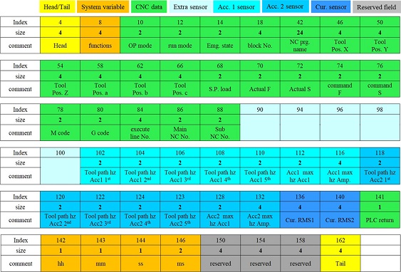
CNC 정보는 정확한 공구 위치와 속도(이송속도, 회전속도)를 제공하나 가공 부하의 크기나 진동에 대한 정보가 부정확하다. 반면, 센서 정보만으로는 정확한 공구 위치를 알 수 없어 가공 상태의 이상 유무를 진단하기 어렵다. 따라서, 가공 상태를 진단하기 위한 CNC 정보와 센서를 결합하여 사용하는 것이 필요하다. 진단 목적에 따라서 센서가 선정된다. 가공 부하를 진단하기 위해서는 전류센서를 활용하여 스핀들 모터의 전류값을 측정하고, 공구떨림을 진단하기 위해서는 음향센서나 가속도센서를 활용한다. 또한, 소재의 절삭력을 측정하기 위해서는 공구동력계(Dynamometer)를 사용한다. 공구 위치와 함께 센서 데이터를 동기화하여 저장한 것을 가공 이력(Machine History)라 할 수 있고, 이러한 가공 이력은
Table 1에서 보는 바와 같이 정의할 수 있다. 가공 시작과 종료 사이에 일정 시간 간격으로 샘플링하여 저장하면
식(4)와 같이 쓸 수 있고, 여기서 Rec
i는 I번째 가공 상태이다
Table 1Machine history structure
Table 1
|
Group |
Field |
Explain |
|
Time |
Machine datetime |
Data collection time |
|
Operation |
Status auto |
OP panel mode:
Eidt, Jog, MDI, Handle |
|
Status run |
Machining state
(Cycle start) |
|
Status emergency |
Error code |
|
Tool Pos. |
X |
Absolute position, x-axis |
|
Y |
Absolute position, y-axis |
|
Z |
Absolute position, z-axis |
|
A |
Absolute position, a-axis |
|
B |
Absolute position, b-axis |
|
C |
Absolute position, c-axis |
Miscell
-Aneous |
Block No. |
Number of sequence |
|
Spindle load |
Spindle loadmeter [%] |
|
Actual feed |
Actual federate |
|
Actual rpm |
Actual spindle speed |
|
Command rpm |
Command spindle speed |
|
Command feed |
Command feedrate |
|
M-code |
Number of m-code |
|
ATC No. |
Number of tool |
|
Sub no |
Number of sub NC-data |
|
Main no |
Number of main NC-data |
|
Sensor |
Microphone |
FFT result, Chatter frequency |
|
Accelerometer |
FFT result, Chatter frequency, RMS |
|
Current |
RMS |
다시 Rec
i는 저장 공간의 효율과 재사용을 위해 일정한 포맷으로 저장하며, CNC 정보와 센서 정보를 포함한다(
Fig. 1).
Fig. 1A packet structure of machine history

3.2 가공 분석
가공 이력 데이터는 절삭 가공된 제품이 어떠한 물리적 상태로 가공이 되었는지 알 수 있는 데이터이다. 최종 형상은 동일할지라도 과부하, 채터, 공구마모, 절삭 조건 등이 가공 전반에 걸쳐 기록되어 있다. 하나의 가공 이력은 제품 하나의 가공 상태를 분석할 수 있는 반면 동일한 제품을 반복 가공할 경우 가공 이력들에 대한 분석은 공구마모, 주축 스핀들 상태, 소재 불균일 등 공정 분석과 장비 예지 보전에 사용될 수 있다.
부품 가공과 같이 동일한 제품을 반복 가공하는 경우 공구 비용은 중요한 생산원가 중 하나이고, 품질을 보장하는 공구 수명을 사전에 지정하여 사용한다.
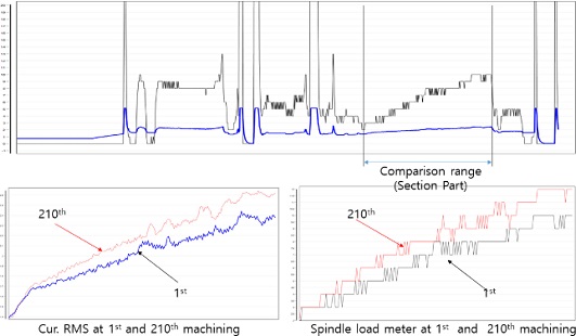
Fig. 3은 500개의 자동차 Hub Bearing의 Section Part를 가공할 때 발생한 가공 부하의 평균과 분산을 보여주고 있다. ①번 영역에서는 주기적으로 40회 가공 후 공구 교환이 발생하나 ②번 영역에서는 과부하 발생으로 25회 가공 후 공구 교환이 발생한 것을 볼 수 있다. ③번 영역에서는 가공 부하 평균이 낮음에서 40회 최대 50회 가공 후 공구 교환이 발생하였다. 즉 공구 수명이 남아 있어도 가공 횟수에 기반하여 공구 교환이 발생하였다.
Fig. 2An example of machine history: Hub bearing of automobile
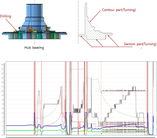
Fig. 3Cutting load variation according to machine count
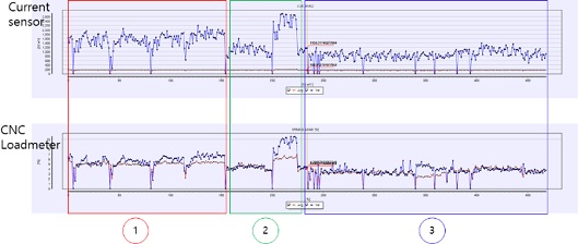
Fig. 4는 새로운 공구를 사용하여 품질에 영향을 주는 횟수까지 가공한 결과를 보여주고 있다. 하나의 공구로 210회까지 가공하였을 때 초기의 가공 부하와 210회 가공 후 가공 부하 차이를 보여주고 있다. 가공 부하 측정을 위해 사용된 전류센서와 CNC 자체 로드미터가 서로 비례관계가 있음을 보여주고 있다(
Fig. 3).
Fig. 4Comparison between the cutting load of 1st and 210th machining

각 영역별 사용된 가공 횟수가 다른 이유는 소재형상의 불균일이 주 원인일 것을 판단되며, 잔존 공구 수명이 남아 있음에도 횟수 기반의 공구 교환은 원가를 상승시키는 원인이 된다. 아울러, 품질 향상을 위해서는 가공 부하를 기준으로 한 공구 수명 관리가 필요함을 알 수 있다. 따라서 CNC 정보에 의해 공구의 정확한 위치를 알고, 그때의 센서값을 활용하여 진단하는 것이 필요하며, 센서와 동기화된 데이터를 가공 이력이라 정의한다.
4. 기준 부하와 적응 제어
4.1 적응 제어(Adaptive Control)
적응 제어는 가공 중 발생하는 가공상태에 따라서 공구이송 및 스핀들 스피드를 제어하는 방법으로 현상이 발생한 후 제어하는 수동적 제어 방식이다(본 연구에서는 채터 제거를 위한 스핀들 스피드의 제어는 다루지 않는다).
Fig. 5에서 보는 바와 같이 상·하한의 두 경계곡선(Upper/Lower Limit) 사이에 가공 부하가 놓이도록 이송속도를 제어하는 방법이다.
Fig. 5Adaptive control
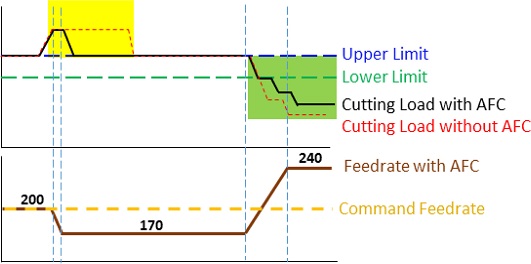
상한보다 가공 부하가 높은 경우(Yellow Zone of
Fig. 5) 이송속도를 감소시키고, 하한보다 낮은 가공 부하가 발생한 경우(Green Zone of
Fig. 5) 이송속도를 증가시킨다. 가공 부하를 균일하게(Balanced) 하는 장점 외에 무부하 구간에서 이송속도를 증가시켜 가공 시간을 단축시킬 수 있다는 이점이 있다. 그러나 가공 부하가 발생한 후 수동적으로 제어하는 방식의 단점을 동시에 갖는다. 즉, 무부하 구간에서 이송속도를 증가시킨 후 소재에 진입하게 되는 경우 공구에 영향을 주어 공구 수명을 단축하거나 파손이 발생할 수 있다. 또한, 부하가 높은 구간에서 이송 속도를 감소시킴으로써 발생하는 생산성 감소와 불균일한 가공 부하 구간에서 빈번한 이송속도 증감에 따른 가공면 품질 저하가 발생할 수 있다.
적응 제어의 수동적 특성에 의한 단점을 제거하기 위해서 사전에 가공 부하에 대한 맵(Map)을 활용한다면 보다 효율적인 제어가 가능하며 적응 제어 중 공구마모/파손 검출이 가능하다. 가공 부하 곡선을 따라서 임계 상하한 곡선(Envelope Curve)을 생성하고 직선 형태에 상하한 값을 대체하면 가공 부하의 크기에 관계없이 일정한 제어가 가능하도록 할 수 있다. 기존 상용화된 소프트웨어에서 NC 데이터 최적화 과정 중에 사용된 공구-소재 접촉면 분석 결과나 절삭력 예측값을 활용할 수 있다. 그러나 고가의 상업용 CAM 시스템은 현장 적응성이 떨어지고, 실제 가공 부하와 예측값의 보정이 필요하며, 가공 현장에 적용하기는 매우 어렵다. 본 연구에서는 반복적인 부품 가공에서 센서 데이터를 공구 위치에 동기화한 가공 이력을 사용하여 가공 부하 맵을 작성하고, 적응 제어와 동시에 공구마모/파손 진단이 가능한 방법을 제시한다.
4.2.1 제어기준곡선(Reference Curve)
새로운 공구로 부품을 가공할 때, 가공 부하를 공구 위치에 따라서 저장하고 각 위치의 정보를 Rec
i로 표시하면 전체 가공 이력은
식(4)와 같이 표시할 수 있다. 특정 가공 위치에서 허용할 수 있는 최대 상한을 임계상한(Upper Limit)이라고 정의하고, 공구가 파손된 경우를 감지하기 위한 최소 하한을 임계하한(Lower Limit)이라고 정의하면,
식(4)의 가공 이력 중에서 공구 위치 i(Rec
i)에서 상한과 하한은
식(5)와
식(6)과 같이 계산된다. 공구 위치 i(Rec
i)에서 가공 부하(Load
i)를 추출하고, 일정한 값(δ
i)을 Offset한 값들의 연속을 제어기준곡선(Reference Curves)이라 한다.
즉, 임의의 가공 위치에서 상한곡선(Upper Limiti)는 공구마모가 최대일 때의 값을 나타내고, 반대로 하한(Lower Limiti)은 공구가 파손된 경우를 진단하는 곡선이 된다. 따라서 가공 부하가 상·하한 곡선을 넘지 않도록 공구 이송속도를 제어하면 기존의 적응 제어에 비해 균일하게 제어할 수 있다.
가공 중 제안한 적응 제어를 위해서는 제어곡선(Reference Curve)이 필요하며, 제어곡선은 장비 특성과 가공 상태를 반영하여 생성되어야 한다. 무부하 상태에서 스핀들 모터의 전류값을 측정하면, 회전수(RPM)에 따라서 크기(Amplitude)가 변화하고(
Fig. 6), 동일한 주축 회전수에서도 부하 편차가 발생한다. 흔들리는 전류값의 최대-최소 크기를 노이즈(
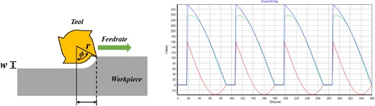
ε)라 할 수 있다. 또한 절삭 조건과 공구의 조합에 의한 절삭력은
Fig. 7에서 보는 바와 같이 일정한 패턴으로 발생하고, 이는 절삭 조건이 동일한 가공에서도 전류 센서값에 진폭이 존재함을 알 수 있다. 따라서 제어임계곡선
식(5)와
식(6)에서 δ
i는 다음
식(7)과 같이 변환하여 쓸 수 있다(
Fig. 8).
Fig. 6Spindle load meter and current by spindle speed at non-cutting
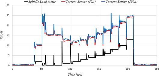
Fig. 7Estimated cutting force (Down milling)

Fig. 8Threshold curve (Blue line: actual load, Red dot line: upper limit)
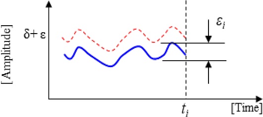
여기서, λ
T는 공구 T의 최대 허용 가공 부하 오차 상수, ε
i는 i 시점에서 진폭의 크기이다. λ
T가 큰 값인 경우 적응 제어(Automatic Feed Control, AFC) 상한 또는 하한 속도로 양극화될 수 있으며, 적은 경우 빈번한 이송속도 제어로 가공면에 영향을 줄 수 있다. ε
i가 큰 경우 이송속도 제어폭을 줄이는 것이 필요하다. 적응 제어의 단점인 수동적인 측면을 고려하면
식(7)에서 상한곡선(Upper Limit
i)은 다시 선행 가공 부하를 반영하는 것이 필요하다. 즉 T
i+1 동안 발생하는 가공 부하 중 최댓값을 선정하는 것이 필요하고, 시간 간격 τ는 CNC와 통신 주기를 감안할 때, 통신 주기의 2-3배를 선정하는 것이 필요하다. 따라서
식(8)은 다음과 같이 쓸 수 있다.
반대로, 하한곡선(Lower Limit
i)는 무부하값보다 항상 큰 값을 가져야 한다. 따라서
식(9)는 다음과 같이 쓸 수 있다.
4.2.2 Proposed Adaptive Control
마모가 발생하지 않은 초기 상태의 공구를 T
new라 한다. T
new로 가공한 가공 이력에서
식(5)와
식(6)을 이용하여 만든 곡선을 각각 임계상하한 곡선이라 하면,
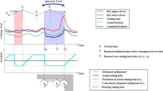
Fig. 9에서 보는 바와 같이 빨간색과 녹색의 곡선을 만들 수 있다. 가공 부하(파란선)에 따라서 이송속도를 증감시킬 수 있으며, t
0 시점에서 가공 부하가 낮더라도 기준 부하 선독을 활용하여 접근 이송속도(Approach Feed)를 적용할 수 있다. 또한 가공 부하의 크기에 관계없이 각 시점에서 상하한 선을 넘지 않는 제어를 통해 공구 수명 및 가공면 품질을 향상시킬 수 있다.
Fig. 9Advanced adaptive control

임의의 가공 시점에서 가공 부하를 Loadi라 하고, 한 번에 변경하는 이송속도 증분값(Feed Override Value)을 현재 속도의 k [%]로 정의할 때 가공 부하에 따른 이속속도 증감 규칙은 다음과 같다.
Rule 1: Loadi 상한(Upper Limiti)를 벗어난 경우 k의 배수를 적용 빠르게 감속시킨다.
Rule 2: 하한(Lower Limiti) 이하의 가공 부하인 경우 k의 배수를 빠르게 가속시킨다.
Rule 3: 하한과 상한 사이에 Loadi가 존재하는 k로 가속시킨다.
Rule 4: 현재 시점 ti에서 ti+Δ 시간 동안 상한를 검색하여 ABS (Upprer Limitk – Loadi) > β 만족하면 접근 이송속도를 적용한다.
4.2.3 적응 제어 중 공구마모/파손 진단
이송속도를 증가시키면 날당 이송량의 증가로 가공 부하는 증가하게 되고, 반대로 감소시키는 경우 가공 부하는 감소하게 된다. 그러나 과도하게 마모된 공구는 이송속도를 감소시켜도 상한을 넘는 경우가 발생한다. 또는 불균일한 소재로 인해 상한을 초과하는 가공 부하가 발생할 수 있다. 소재의 형상이 균일하다고 가정할 때 적응 제어 중 최소 이송속도로 가공 시 일정시간(Δt) 상한(Upper Limiti)를 초과하는 경우 과도한 공구마모로 판단할 수 있고, 하한보다 낮은 부하가 지속될 때 공구파손으로 진단할 수 있다.
4.3 적응 제어와 공구마모 진단
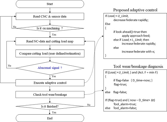
Fig. 10은 제안한 적응 제어 흐름도를 보여주고 있다. 가공이 시작되면 현재 NC 데이터의 제어기준곡선을 찾는다. 공구 이송에 따라서 제어곡선을 맵핑하고, 현재 가공 위치에서 가공 부하를 계산한다. 가공 부하가 제어곡선의 상한, 하한과 비교하여 Rules 1부터 4를 적용하여 이송속도를 증감한다. 다음으로 현재의 공구 상태가 정상인지 판단하기 위해 공구와 이송속도의 관계를 비교하여 일정 시간 상한을 초과하거나 하한 미만인 경우 공구 알람을 발생시킨다.
Fig. 10Proposed adaptive control

5. Experiment
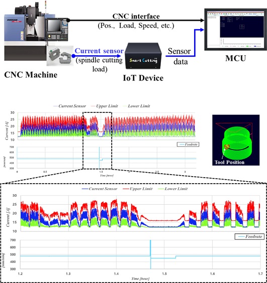
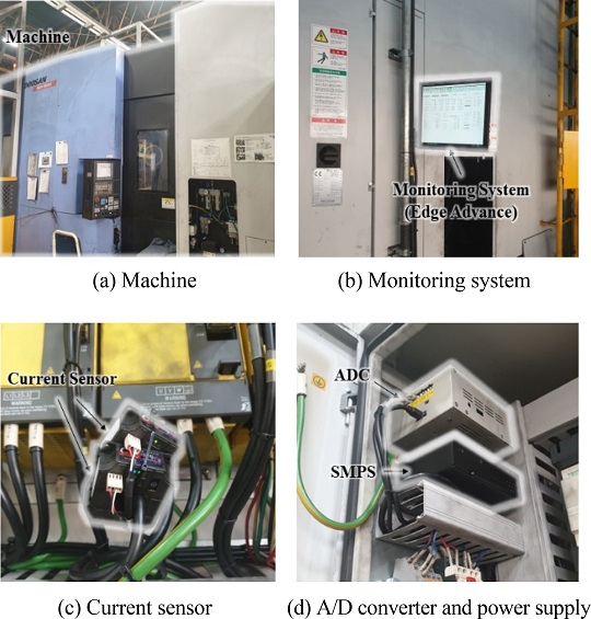
제안한 적응 제어 방법의 검증을 위해 실제 공작기계의 스핀들 하우징 가공에 적용하였다. 가공 부하 측정을 위해 사용한 전류센서의 사양은
Table 2와 같고, 사용한 장비는 두산공작기계 HLPS #3이다.
Figs. 11과
12에서 보는 바와 같이 스핀들 드라이브의 출력 단자에 전류센서를 부착하였고, CNC와 통신은 이더넷을 통해 공구 위치, 이송속도, 스핀들 스피드 등의 모니터링 가능한 Edge Advance를 활용하였다.
Table 2 Specification of hardware
Table 2
|
No. |
List |
Explain/Value |
|
1. |
Machine type |
3axis, Horizental |
|
2. |
Tool type |
Facemill cutter |
|
Tool diameter [mm] |
200 |
|
3. |
Workpiece material |
Cast iron |
|
4. |
Monitoring system |
Edge advance |
|
5. |
Current sensor 1 Max. Range [A] |
50 |
|
Current sensor 2 Max. Range [A] |
100 |
|
6. |
ADC sampling [Hz] |
115,200 |
Fig. 11 Schema of measurement system
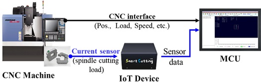
Fig. 12 Machine and experiment setup
5.1 제어임계곡선
우선, 대상 공작기계에서 엔드밀 공정에서의 이송속도를 제어하기 위해 Edge Advance를 통해서 저장된 가공 이력을 활용하여 제어임계곡선을 생성하였다.
Fig. 13에서 파란선은 실제 가공 부하를 나타내며 실제 가공 부하를
식(8)과
식(9)를 이용하여 임계곡선을 생성하였다.
Fig. 13에서 빨강선은 상한 임계곡선이며, 초록선은 하한 임계곡선을 나타낸다. 이렇게 생성된 제어임계곡선은 가공 상태를 반영되기 때문에 동일한 제품의 가공에서 활용이 가능하며, 가공 위치에 따른 가공 부하의 특성을 확인할 수 있는 특징이 있다. 예를 들어 공구가 진입하여 부하가 급격히 상승하는 가공 위치, 공구가 완전히 진입하여 부하가 유지되는 가공 위치, 공구가 진출하면서 부하가 급격히 하락하는 가공 위치 등을 파악할 수 있다.
Fig. 13Upper and lower limit: Redline is upper limit, green line is lower limit, blue line is actual load

5.2 실험 결과
본 논문에서는 기존의 실제 가공 부하 데이터를 기반으로 생성된 제어임계곡선을 활용하여 가공 위치, 가공 특성을 고려한 적응 제어 방법을 제안하였다.
Fig. 13의 제어임계곡선에서 공구가 진입하는 가공 위치에서는 접근 이송속도를 적용하고, 가공 중 실제 가공 부하에 따른 공구의 이송속도를 제어하며, 동시에 과부하, 공구마모 및 파손을 진단한다. 이러한 적응 제어 방법을 적용한 가공 실험을 진행하였다.
Fig. 14는 적응 제어 방법을 적용하여 가공한 가공 이력 데이터이다. 공구가 다음 레이어(Layer)로 진입하는 가공 위치에서 접근 이송속도가 적용되어 이송속도를 90%로 감속하여 진입하도록 제어하였다. 공구가 진입한 후 가공 구간에서는 가공 부하가 상한 임계곡선보다 낮은 가공 구간에서는 이송속도를 120%까지 가속하여 가공을 진행하였다. 또한 가공 중 가공 부하가 상한 임계곡선을 초과하는 가공구간에서 이송속도 감속제어를 진행하였다.
Fig. 14Analysis of machine history data with adaptive feed control
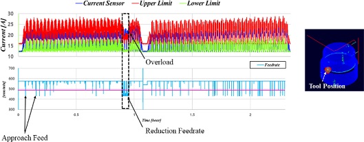
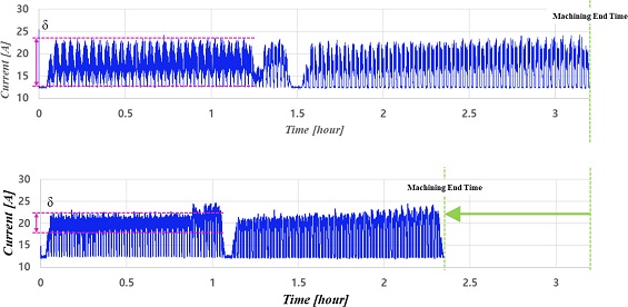
Fig. 15에서는 동일한 가공에 대해서 제어를 하지 않은 가공 이력 데이터와 적응 제어 방법을 적용한 가공 이력 데이터에서 가공 부하를 비교하였다. 제어를 하지 않은 가공에 비해 적응 제어를 적용한 가공의 가공 시간이 17% 감소하였다. 접근 이송 속도로 인해 감속 구간이 발생하였지만 가공 부하가 상한 임계곡선보다 낮은 가공 구간에서 120%까지 가속을 하였기에 가공 시간을 감축할 수 있었다. 또한, 가공 부하의 흔들림(
δ)은 제어를 하지 않은 가공보다 적응 제어 방법을 적용하면 감소시킬 수 있다. 이는 공구에 작용하는 부하를 균일하게 제어할 수 있으므로 공구 수명을 향상시킬 수 있다.
Table 3Cutting and control conditions
Table 3
|
No. |
List |
Value |
|
1. |
Spindle speed [rpm] |
308 |
|
2. |
Feedrate [mm/min] |
480 |
|
3. |
Feed override range [%] |
90-120 |
Fig. 15Compared machine history data between without AFC and with AFC
6. Conclusion
본 논문에서는 가공 공정 최적화의 방안으로 반복 가공 생산에서 실제 측정한 부하 데이터를 기반으로 가공 중 이송속도 적응 제어 방법을 제안하였다. 공구 경로 최적화는 가공 중 발생하는 공구마모, 소재의 불균일, 공구떨림 등을 고려하여도 예측 데이터를 기반으로 하여 오차를 수반한다. 그러므로 가공 중 발생하는 상황에 대응하여 실시간 공정의 최적화가 필요하다.
제안한 방법은 가공 부하와 NC 데이터를 동기화하여 저장하고, 저장된 가공 이력 데이터를 분석하여 적응 제어를 위한 임계곡선을 생성한다. 임계곡선을 활용하여 가공 중 가공 부하가 하한 임계곡선보다 낮으면 공구의 이송속도를 가속하고, 가공 부하가 상한 임계곡선보다 높으면 공구의 이송속도를 감속하도록 제어한다. 또한 가공 이력 데이터를 기반으로 생성한 임계곡선은 공구의 진입 위치를 파악하고 있기에 공구와 소재가 만나는 시점에 접근 이송속도를 적용하여 진입 시에 발생하는 공구의 충격을 감소하였다.
이러한 임계곡선을 활용하여 가공실험을 진행하였으며, 제어를 진행하지 않은 가공보다 적응 제어의 제어 범위 90-120%까지 적용한 가공에서 가공 시간은 17%를 감소하였다. 이러한 가공 실험 결과를 통해 단순히 NC 데이터에서 이송속도를 120%로 향상시키는 것과는 다르게 본 논문에서 제안한 적응 제어 방법은 접근 이송속도와 임계곡선으로 인한 이송속도 제어를 통해 공구에 가해지는 가공 부하를 균일하게 제어하였다. 이는 가공 시간을 단축하면서도 공구의 수명 향상을 기대할 수 있다. 하지만 가공 이력 데이터를 기반으로 하여 임계곡선을 설정하더라도 설정값에 따라 다른 제어 결과를 나타낸다. 적응 제어의 가공 공정 최적화 효과를 극대화하기 위해 추후에 임계곡선의 개선에 대한 연구가 필요하다.
REFERENCES
- 1.
Park, S. C., & Choi, B. K., (2000). Tool-path planning for direction-parallel area milling. Computer-Aided Design, 32(1), 17-25.
10.1016/S0010-4485(99)00080-9
- 2.
Lazoglu, I., Manav, C., & Murtezaoglu, Y., (2009). Tool path optimization for free form surface machining. CIRP Annals, 58(1), 101-104.
10.1016/j.cirp.2009.03.054
- 3.
Jin, Y.-A., He, Y., Fu, J.-Z., Gan, W.-F., & Lin, Z.-W., (2014). Optimization of tool-path generation for material extrusion-based additive manufacturing technology. Additive Manufacturing, 1(4), 32-47.
10.1016/j.addma.2014.08.004
- 4.
Wang, H., Jang, P., & Stori, J. A., (2005). A metric-based approach to two-dimensional (2D) tool-path optimization for high-speed machining. Journal of Manufacturing Science and Engineering, 127(1) 33-48.
10.1115/1.1830492
- 5.
Pezer, D. (2016). Efficiency of tool path optimization using genetic algorithm in relation to the optimization achieved with the cam software. Procedia Engineering, 149, 374-379.
10.1016/j.proeng.2016.06.681
- 6.
Erkorkmaz, K., Layegh, S. E., Lazoglu, I., & Erdim, H., (2013). Feedrate optimization for freeform milling considering constraints from the feed drive system and process mechanics. CIRP Annals, 62(1), 395-398.
10.1016/j.cirp.2013.03.084
- 7.
Mikó, B., & Beňo, J., (2014). Effect of the working diameter to the surface quality in free-form surface milling. Key Engineering Materials, 581, 372-377.
10.4028/www.scientific.net/KEM.581.372
- 8.
Feng, H.-Y., & Su, N., (2000). Integrated tool path and feed rate optimization for the finishing machining of 3D plane surfaces. International Journal of Machine Tools and Manufacture, 40(11), 1557-1572.
10.1016/S0890-6955(00)00025-0
- 9.
Xie, J., Zhao, P., Hu, P., Yin, Y., Zhou, H., et al., (2021). Multi-objective feed rate optimization of three-axis rough milling based on artificial neural network. The International Journal of Advanced Manufacturing Technology, 114(5), 1323-1339.
10.1007/s00170-021-06902-0
- 10.
Altintas, Y., & Aslan, D., (2017). Integration of virtual and online machining process control and monitoring. CIRP Annals, 66(1), 349-352.
10.1016/j.cirp.2017.04.047
- 11.
Kuntoğlu, M., Salur, E., Gupta, M. K., Sarıkaya, M., & Pimenov, D. Y., A state-of-the-art review on sensors and signal processing systems in mechanical machining processes. (2021). The International Journal of Advanced Manufacturing Technology, 116(9), 2711-2735.
10.1007/s00170-021-07425-4
- 12.
Hassan, M., Sadek, A., Attia, M. H., & Thomson, V., (2018). Intelligent machining: Real-time tool condition monitoring and intelligent adaptive control systems. Journal of Machine Engineering, 18(1), 5-17.
10.5604/01.3001.0010.8811
- 13.
Zhu, K., & Zhang, Y., (2018). A cyber-physical production system framework of smart CNC machining monitoring system. IEEE/ASME Transactions on Mechatronics, 23(6), 2579-2586.
10.1109/TMECH.2018.2834622
- 14.
Thepsonthi, T., & Özel, T., (2014). An integrated toolpath and process parameter optimization for high-performance micro-milling process of Ti-6Al-4V titanium alloy. The International Journal of Advanced Manufacturing Technology, 75(1), 57-75.
10.1007/s00170-014-6102-2
- 15.
Özel, T., Thepsonthi, T., Ulutan, D., & Kaftanoğlu, B., (2011). Experiments and finite element simulations on micro-milling of Ti-6Al-4V alloy with uncoated and cBN coated micro-tools. CIRP Annals, 60(1), 85-88.
10.1016/j.cirp.2011.03.087
- 16.
Munoa, J., Beudaert, X., Dombovari, Z., Altintas, Y., Budak, E., et al., (2016). Chatter suppression techniques in metal cutting. CIRP Annals, 65(2), 785-808.
10.1016/j.cirp.2016.06.004
Biography
- Seung-Gi Kim
Researcher in the CAMTIC. His research interest is machining and control.
- Eun-Young Heo
Senior Researcher in the CAMTIC. His research interest is machining and control.
- Hee-Gwan Lee
Principal Researcher in the CAMTIC. His research interest is machining and control.
- Jum-Jong Park
General Manager in the Doosan Machine Tools. His research interest is machining and ICT
- Dong-Won Kim
Professor, Industrial and Information Systems Engineering, Jeonbuk National University. His research interest is computer integrated manufacturing