ABSTRACT
The gear has a wide range of transmitted force as various gear ratios are possible using a combination of teeth. It can transmit power reliably and cause relatively little vibration and noise. For this reason, the application of reducers of electric vehicles is being expanded. Vibration noise generated from gears is propagated into the quiet interior of a vehicle, causing various claims. In most gear studies, transmission error has been pointed out as the main cause of vibration noise of gears. Transmission errors have various causes, including design factors, manufacturing factors, and assembly factors. In general, when predicting transmission error through finite element analysis, design factors play an important role without considering manufacturing factors or assembly factors. In this study, relationships among important design variables (gear module, compensation rate, load torque, and transmission error) in gear design were investigated using analytical and experimental methods. In addition, a method of predicting gear meshing stiffness through the predicted gear transmission error was proposed to obtain variation of meshing stiffness due to changes of gear design parameters.
-
KEYWORDS: Transmission error, Meshing stiffness, Finite element analysis, Gear system
-
KEYWORDS: 전달오차, 물림강성, 유한요소해석, 기어시스템
1. 서론
최근 기어는 자동차, 산업용 기계, 항공기, 선박 등 산업 전반에 걸쳐 여러 분야에서 이용되고 있다. 기어의 장점으로는 잇수의 조합에 따라 다양한 기어비가 가능하여 전달력의 범위가 넓으며, 동력을 확실하게 전달할 수 있고 비교적 적은 진동소음을 유발한다. 이로 인해 전기자동차의 감속기에 적용이 확대되고 있는데 기어에서 발생하는 진동 및 소음이 정숙한 차 실내로 전파되어 이러한 문제를 해결하고자 연구가 많이 진행되고 있다. 대부분 기어의 연구에서 기어의 진동 소음의 주요 원인으로 전달오차를 지목한다
[1,
2]. 전달오차는 다양한 원인에 의해 발생하게 되는데 크게 설계요인, 제조요인, 조립요인이 있다. 일반적으로 유한요소해석을 통한 전달오차 예측에서는 제조요인과 조립요인을 고려하지 않고 설계요인이 중요하게 작용한다
[3].
본 연구에서는 기어 설계에서 중요한 설계 변수인 기어 모듈, 전위 비율 그리고 부하 토크의 변화에 따른 전달오차와의 관계를 해석과 시험적 방법으로 알아보고자 하였다. 또한 예측한 기어 전달오차를 통해 기어 물림강성을 예측하는 방법을 제시하고 기어 설계변수의 변화에 따른 물림강성을 구하고자 한다.
2. 기어의 전달오차와 물림강성
2.1 기어 전달오차
기어는 물성치를 가지는 유연체로 기어가 맞물릴 때 접촉하중에 의해 이의 처짐이 발생하게 된다. 이러한 과정이 기어가 회전하는 동안 물림률에 의해서 규칙적인 주기를 가지게 된다.
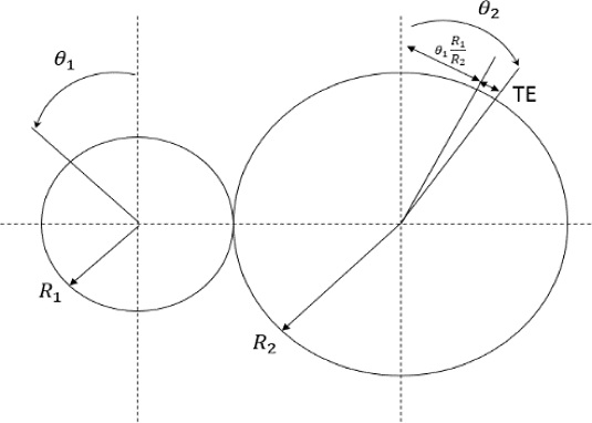
Fig. 1과 같이 구동 기어와 피동 기어의 회전 차이에서 발생하는 오차를 전달오차라고 하고
식(1)과 같이 나타낸다
[4].
Fig. 1Definition of transmission error
2.2 기어 물림강성
물림강성이란 전달오차의 최대진폭(Peak to Peak, PTP)치 변화에 의해 가지는 기어의 특성이다. 이러한 물림강성은 전달오차와 접촉력(Contact Force)에 의해 구해지는데 기어가 가지는 물림률(Contact Ratio)에 따라 특성이 다르다. 일반적으로 스퍼기어는 물림률이 1-2 값을 가지며 헬리컬 기어는 2-3 값을 가진다. 스퍼 기어의 경우를 가정해본다. 한 쌍이 맞물릴 경우의 물림강성 K
m은
식(2)와 같이 계산된다
[5].
여기서
F는 접촉력이고,
δp,
δg는 각각 구동 기어, 피동 기어의 처짐량를 나타낸다. 기어가 두 쌍 맞물릴 경우이다. 이 경우에는
식(3)과 같이 계산된다.
이처럼 스퍼 기어의 물림강성은 계산할 수 있고, 마찬가지로 헬리컬 기어 또한 두 쌍의 기어가 맞물릴 경우와 세 쌍의 기어가 맞물릴 경우를 나누어 물림강성을 계산할 수 있다. 전체 처짐과 접촉하중의 조건은
식(4)와
식(5)이고, 이를
식(3)에 적용하면 기어 물림강성은 다음
식(6)과 같다.
위
식(6)에서 처짐량은 결국 전달오차를 의미하며,
식(7)과 같이 나타낼 수 있다.
전체 접촉하중 F는 동일하므로 물림강성은 전달오차와 반비례 관계를 가진다.
3. 기어 전달오차 해석과 시험
3.1 타겟 기어 제원
타겟 기어는 실제 공작기계 공작물 이송 갠트리 로봇용 기어에 사용하는 기어로 사용했다.
Table 1은 타겟 기어의 제원으로 스퍼 기어 #1은 모듈이 1.59이고, 스퍼 기어 #2는 모듈이 2.39이다. 두 기어에서 모듈이외의 모든 제원은 동일하게 가져가도록 하였다.
Table 1Target gears design parameters
Table 1
|
Parameter |
Spur |
|
#1 |
#2 |
|
Number of teeth |
36 |
24 |
|
Normal module [mm] |
1.59 |
2.39 |
|
Normal pressure angle [o] |
20 |
20 |
|
Normal helix angle [o] |
0 |
0 |
|
Face width [mm] |
14.50 |
19.50 |
|
Center distance [mm] |
57.29 |
57.29 |
|
Tooth addendum [mm] |
1.59 |
2.39 |
|
Tooth dedendum [mm] |
1.99 |
2.99 |
|
Shaft diameter [mm] |
42.00 |
42.00 |
|
Total contact ratio |
1.69 |
1.60 |
3.2 유한요소해석기법을 이용한 전달오차 해석
3.2.1 해석 기어 모델링
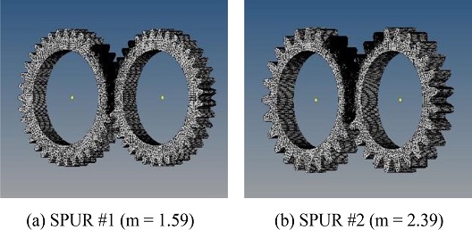
타켓 기어의 유한요소 모델은 상용프로그램인 하이퍼메쉬(Hypermesh)를 이용하여 모델링하였다. 유한요소해석은 대체적으로 정밀한 데이터를 얻을 수 있는 장점을 가지고 있으나 해석 시간이 오래 걸리는 단점을 가지고 있다. 이러한 단점을 최소화하기 위해서는 요소(Element)수를 줄여 해석 모델링을 최적화하는 것이 중요하다
[6]. 그러기 위해서 해석시간인 1초 동안 각 기어에서 몇 개의 이가 물림이 일어나는지 예측했다. 자동메쉬(Automesh) 기능을 이용하여 생성된 해석 모델링 요소수보다 2/3 절감한 1/3 요소수를 가지는 해석 모델링을 생성하였다. 각각 스퍼 기어 #1은 약 70만개, 스퍼 기어 #2는 약 75만개로 요소수를 가진다.
Fig. 2는 하이퍼메쉬를 이용하여 타겟 기어를 모델링한 모습이다.
Fig. 2FE modeling of target gears for analysis
3.2.2 주요 설계변수에 따른 전달오차 해석
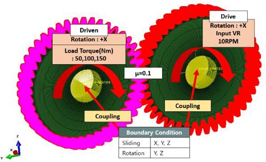
유한요소해석은 해석 통합 솔루션인 ABAQUS 프로그램을 이용하여 진행하였다. 해석에 사용된 기어의 물성치로 탄성계수는 200 GPa, 푸아송의 비는 0.285, 밀도는 7.85 g/cm
3이다. 해석조건은 실험과 동일하게
Table 3과 같이 적용하였다.
Fig. 3은 ABAQUS상에서의 해석에 사용된 기어 경계 조건을 적용한 모습이다. 주요 설계변수 부하 토크, 전위 비율, 기어 모듈의 변화에 따른 전달오차 변화를 알아보고자 하였다
[7].
Table 2Analysis condition of design parameter
Table 2
|
Condition |
|
Gear module |
1.59(SPUR #1), 2.39(SPUR #2) |
|
Load torque [Nm] |
50, 100, 150 |
|
Compensation rate [%] |
0, 5, 10, 15 |
|
Rotation speed [RPM] |
10 (1/6 rev per 1s) |
|
Friction coefficient |
0.1 |
Table 3Transmission error value of Spur gear due to design parameter variation
Table 3
Compensation
rate/
Load torque |
Spur #1 (m = 1.59) |
Spur #2 (m = 2.39) |
Max
[μm] |
Min
[μm] |
PTP
[μm] |
Max
[μm] |
Min
[μm] |
PTP
[μm] |
|
0% |
50 Nm |
1.01 |
-0.99 |
2.00 |
1.77 |
-1.16 |
2.93 |
|
100 Nm |
2.39 |
-2.08 |
4.47 |
3.16 |
-2.04 |
5.20 |
|
150 Nm |
3.33 |
-3.37 |
6.70 |
3.82 |
-3.48 |
7.30 |
|
5% |
50 Nm |
1.62 |
-1.19 |
2.81 |
2.16 |
-0.87 |
3.03 |
|
100 Nm |
2.98 |
-1.94 |
4.92 |
3.06 |
-2.21 |
5.27 |
|
150 Nm |
3.96 |
-3.41 |
7.37 |
4.26 |
-3.23 |
7.49 |
|
10% |
50 Nm |
1.36 |
-1.87 |
3.23 |
1.99 |
-1.33 |
3.32 |
|
100 Nm |
2.85 |
-2.45 |
5.30 |
3.18 |
-2.26 |
5.44 |
|
150 Nm |
3.79 |
-3.73 |
7.52 |
4.34 |
-3.37 |
7.71 |
|
15% |
50 Nm |
1.67 |
-1.59 |
3.26 |
2.48 |
-0.79 |
3.27 |
|
100 Nm |
2.75 |
-2.66 |
5.41 |
3.84 |
-1.76 |
5.60 |
|
150 Nm |
4.28 |
-3.61 |
7.89 |
5.20 |
-2.79 |
7.99 |
Fig. 3Boundary condition for analysis

3.2.3 해석 결과 및 고찰
Fig. 3에서 유한요소해석을 통해 각각의 부하 토크와 거리에 대한 전위 조건에서의 3주기에 해당하는 스퍼 기어 전달오차의 결과 그래프를 산출하여
Table 3에서 1주기에 해당하는 최댓값, 최솟값 그리고 최대진폭값을 나타내었다. 전체적으로 전달오차는 -5에서 5 μm 사이 범위에서 나타난다는 것을 알 수 있다.
실질적인 소음 및 진동의 원인은 물림강성의 변화인 전달오차의 최대진폭에 의해 발생하므로 모든 조건에서 최대진폭값을 확인하여 비교분석할 수 있다.
Fig. 4와
Table 3에서 전달오차를 각각 설계변수인 부하 토크, 전위, 기어 모듈에 대해 나타내면 다음을 알 수 있다.
Fig. 4Transmission error according to compensation rate and load torque in spur gear #1, #2
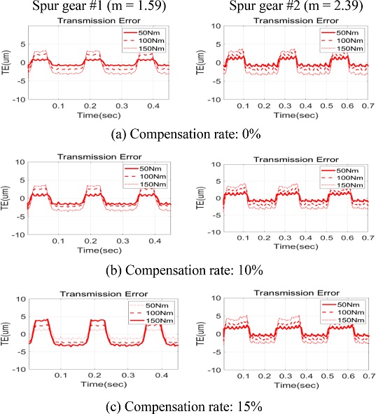
첫째로 전위를 기준으로 할 때, 스퍼 기어 #1, 스퍼 기어 #2에서 전위가 증가할수록 최대진폭값이 적은 범위에서 선형적으로 증가되는 것을 알 수 있다. 둘째로 부하 토크를 50에서 150 Nm로 증가할 때 최대진폭값의 증가 폭이 가장 커서 3배 이상의 값을 가지는 것을 알 수 있다. 셋째로 모듈이 다른 스퍼 기어 #1과 스퍼 기어 #2를 비교할 수 있는데 모든 조건에서 스퍼 기어 #2의 최대진폭값이 작은 범위에서 증가됨을 알 수 있다.
3.3 테스트 벤치를 이용한 전달오차 측정시험
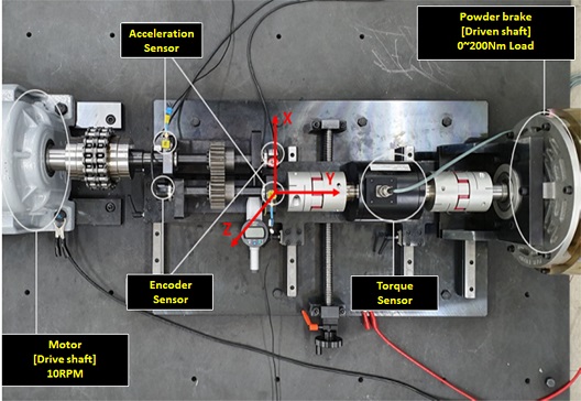
3.3.1 테스트 벤치 구성 및 측정 조건
유한요소해석과 실제 실험의 전달오차와 진동의 비교 검증을 위해 기어의 전달오차와 진동을 측정할 수 있는 시스템을 구성하였다. 해석 조건과 동일하게 준정적 상태로 만들어주기 위해 10 RPM인 저속에서 실험을 진행할 수 있는 테스트 벤치를
Fig. 5와 같이 제작하였다. 구동 기어와 피동 기어의 회전 각속도를 측정하기 위해 각각의 회전축에 5,000 PPR 분해능의 엔코더(Autonics, E40H12)를 부착하였다. 우선 구동 기어 측에 정격전압 10 V, 최대 회전속도 2,000 RPM의 모터(TG-H181)를 장착하였다. 또한 피동 기어에 부하를 인가하기 위해 최대 200 Nm의 파우더 브레이크를 설치하고 1-200 Nm까지 부하가 가능하도록 하였다. 최종적으로 엔코더, 토크센서, 가속서센서 데이터를 데이터프론트앤드(Muller BBM, MKII)를 이용하여 측정 분석하였다.
Fig. 5Test bench for gear experiment
3.3.2 시험 결과 및 고찰
테스트 벤치를 통한 실험은 해석과 동일한 조건에서 수행하였다.
Fig. 6에서 측정시험 전달오차가 해석보다 비교적 정연하지 않는 것은 해석에서 고려되지 않은 기어의 축 변형, 기어 피치오차, 기어 표면 상태 등의 요인에 기인한다. 전체적으로 실험전달오차는 –50 - +50 μm 사이 범위에서 나타난다는 것을 알 수 있다.
Fig. 7과
Table 4의 실험 결과에서 전위 비율, 부하 토크, 기어 모듈에 따른 전달오차의 변동은 해석 결과와 동일한 경향을 보임을 알 수 있다.
Fig. 6Transmission error according to compensation rate and load torque in spur gear #1, #2
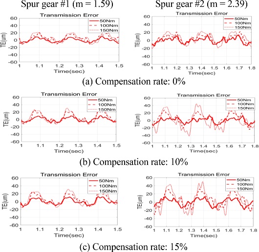
Fig. 7Contour plot of transmission error PTP due to load torque and compensation rate variation in spur gear #1, #2
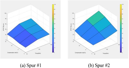
Table 4Transmission error value of spur gear due to design parameter variation
Table 4
Compensation
rate/
Load torque |
Spur #1 |
Spur #2 |
Max
[μm] |
Min
[μm] |
PTP
[μm] |
Max
[μm] |
Min
[μm] |
PTP
[μm] |
|
0% |
50 Nm |
10.20 |
-8.69 |
18.89 |
12.51 |
-15.49 |
28.00 |
|
100 Nm |
14.92 |
-16.26 |
31.18 |
16.53 |
-17.12 |
33.62 |
|
150 Nm |
15.56 |
-18.21 |
33.76 |
21.51 |
-25.37 |
46.89 |
|
5% |
50 Nm |
9.89 |
-8.94 |
18.83 |
12.51 |
-15.49 |
28.00 |
|
100 Nm |
17.78 |
-17.22 |
35.00 |
17.26 |
-26.17 |
43.43 |
|
150 Nm |
20.51 |
-15.95 |
36.46 |
29.51 |
-27.79 |
57.30 |
|
10% |
50 Nm |
11.86 |
-11.04 |
22.90 |
13.75 |
-15.27 |
29.01 |
|
100 Nm |
18.79 |
-19.42 |
38.22 |
21.47 |
-31.74 |
53.21 |
|
150 Nm |
24.13 |
-17.75 |
41.87 |
34.01 |
-34.61 |
68.62 |
|
15% |
50 Nm |
12.32 |
-10.84 |
23.16 |
15.24 |
-21.13 |
36.37 |
|
100 Nm |
22.89 |
-21.69 |
44.59 |
24.04 |
-35.48 |
59.52 |
|
150 Nm |
26.23 |
-21.03 |
47.26 |
38.12 |
-37.56 |
75.67 |
해석과 시험에서의 전달오차 최대진폭값을 비교한 결과로부터 다음을 알 수 있다. 첫째로 전위 비율, 기어 모듈에 비교해서 부하 토크 증가에 가장 민감하게 전달오차 최대진폭이 증가한다. 둘째로 기어 모듈, 전위 비율의 증가에 따라 전달오차 최대진폭값은 비교적 작게 선형적으로 증가한다. 셋째로 기어 물림률과 기어 모듈의 반비례 관계에서 알 수 있듯이 전달오차 최대진폭값은 해석과 시험에서 동일하게 물림률이 큰 스퍼 기어 #1이 전달오차가 작게 나타났다.
Table 5Contact force due to load torque
Table 5
|
Contact force |
Load torque |
|
50 Nm |
100 Nm |
150 Nm |
|
Spur #1 [N] |
1,750 |
3,500 |
5,250 |
|
Spur #2 [N] |
1,750 |
3,500 |
5,250 |
4. 기어 전달오차를 이용한 물림강성 예측
시험을 통해 계측된 스퍼 기어의 전달오차를 이용하여
식(7)에 의해 기어의 물림강성을 예측하고자 하였는데, 물림강성은 해당하는 부하 토크와 전달오차를 이용하여 계산하였다. 사용된 스퍼 기어 #1, #2의 피치 지름이 동일하기 때문에 접촉력은 동일하게 나타난다. 접촉력이 동일하기 때문에 전달오차가 클수록 물림강성은 작게 나타나게 된다.
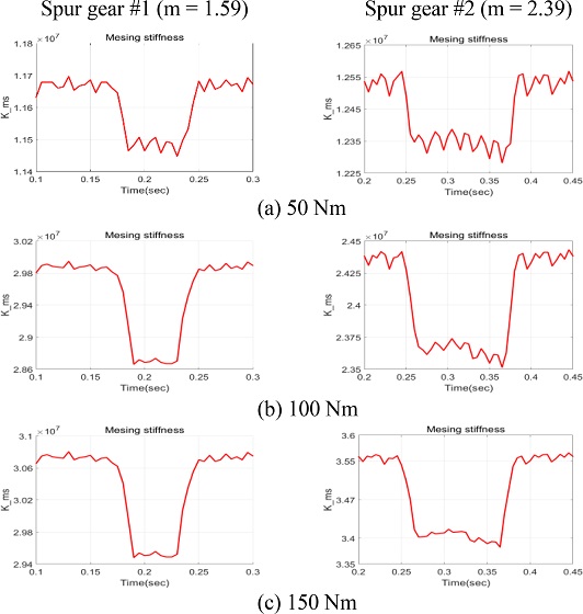
Fig. 8은 한 쌍의 구동 기어와 피동 기어가 접촉하는 주기에서의 물림강성 변화를 보여준다. 스퍼 기어 #1, #2에서 동강성은 동일 재료로 만들어진 기어의 물림강성값과 비슷한 값을 가지며
[5], 각각 최대 0.1 × 10
7, 0.14 × 10
7 N/m의 변동을 보이고 있는데, 이러한 동강성의 변화는 회전 토크의 변화를 가져오고 이는 피동 기어측의 축, 베어링, 기어박스에 가진력으로 작동하게 된다. 전달오차와 동일하게 부하 토크에 가장 민감하게 증가하고 기어 모듈, 전위 비율에 비례적인 것을 알 수 있다. 현재 ADAMS 기반 기어 전달오차 기반 기어박스 진동예측에서 예측된 동강성을 기반으로 진동예측모델을 구성하고자 하고 있다.
Fig. 8 Predicted meshing stiffness due to load torque and gear module

5. 결론
본 논문에서는 부하 토크, 전위 비율 그리고 기어 모듈의 변화에 따른 스퍼 기어의 전달오차와 물림강성을 예측하기 위한 해석과 실험을 수행하였다.
첫째로 해석과 실험에서 동일하게 부하 토크가 증가에 가장 민감하게 전달오차의 최대진폭이 증가하는 것을 알 수 있다. 동일하게 전위 비율, 기어 모듈이 증가함에 따라 전달오차 최대진폭이 작게 증가하였다. 해석 실험에서 동일하게 부하 토크, 전위 비율 그리고 기어 모듈과 전달오차 사이에 비례관계가 성립하고 있다. 둘째로 전달오차를 통해 예측된 기어 물림강성을 예측하는 방법을 제시하였으며, 이를 통해 예측된 물림강성은 부하 토크, 기어 모듈에 비례적 관계를 가지는 것을 확인하였다.
이러한 물림강성 예측 연구를 바탕으로 기어 전달오차로 인한 회전 토크 불균형이 발생하고, 축과 베어링을 통해 기어박스 진동소음을 예측하는 연구를 진행할 예정이다.
ACKNOWLEDGMENTS
본 논문은 2019학년도 인제대학교 학술연구 조성비 보조에 의한 것임.
REFERENCES
- 1.
Curtis, S., Pears, J., Palmer, D., Eccles, M., Poon, A., Kim, M.-G., Jeon, G.-Y., Kim, J.-K., Joo, S.-H., (2005), An analytical method to reduce gear whine noise, including validation with test data, SAE Transactions, 2195-2202.
10.4271/2005-01-1819
- 2.
Perret-Liaudet, J., Carbonelli, A., Rigaud, E., Nelain, B., Bouvet, P., Vialonga, C. J., Modeling of gearbox whining noise, SAE Technical Paper.
- 3.
- 4.
Endo H., (2005), A study of gear faults by simulation and the development of differential diagnostic techniques, Ph.D. Thesis, UNSW Sydney.
- 5.
Raghuwanshi, N. K., Parey, A., (2017), Experimental measurement of spur gear mesh stiffness using digital image correlation techniquem, Measurement, 111, 93-104.
10.1016/j.measurement.2017.07.034
- 6.
Rigaud, E., Barday, D., (1999), Modelling and analysis of static transmission error. Effect of wheel body deformation and interactions between adjacent loaded teeth, Proceedings of the 4th World Congress on Gearing and Power Transmission, 1961-1972.
https://hal.archives-ouvertes.fr/hal-00121847
- 7.
Biography
- Byeongjun Kim
M.Sc. degree student in the Department of Mechanical Engineering, Inje University. His research interest is noise and vibration reduction of mechanical and automotive components.
- Younghoon Lee
M.Sc. degree student in the Department of Mechanical Engineering, Inje University. His research interest is noise and vibration reduction of mechanical and automotive components.
- Hyeongjun Kim
M.Sc. degree student in the Department of Mechanical Engineering, Inje University. His research interest is noise and vibration reduction of mechanical and automotive components.
- Kwangsuk Boo
Professor in the Department of Mechanical Engineering, Inje University. His research interest is noise and vibration reduction of mechanical and automotive components.
- Heungseob Kim
Professor in the Department of Mechanical Engineering, Inje University. His research interest is noise and vibration reduction of mechanical and automotive components.
Citations
Citations to this article as recorded by

- Development of a Prediction Model for the Gear Whine Noise of Transmission Using Machine Learning
Sun-Hyoung Lee, Kwang-Phil Park
International Journal of Precision Engineering and Manufacturing.2023; 24(10): 1793. CrossRef