ABSTRACT
In this study, the disturbance torque that maintains the gimbal at a specific angle during the centrifugal acceleration test was analyzed. Newton's Second Law for Rotation was applied, to calculate the disturbance torque. A Theoretic solution for calculating the disturbance torque was derived, by separating the horizontal/vertical components of the moment of inertia. The Theoretic solution was verified, by numerical analysis (RecurDyn) of the simplified Gimbal model. To include the effect of acceleration, the distance between the central axis of the gimbal and the accelerated test equipment was applied as 0 and L (non-Zero). As a result of the analysis, it was found that the main disturbance torque is not related to acceleration, but to self-centrifugal force caused by rotation. A centrifugal acceleration test was conducted, to verify the operational performance of gimbal. The disturbance torque was calculated, by measuring the torque used to operate the gimbal's motor. The result was compared with the disturbance torque, calculated by the Theoretic solution of the gimbal. The error between the result of test and Theoretic solution of torque was less than 4.5%.
-
KEYWORDS: Centrifugal acceleration test system, Centrifugal force, Moment of inertia, Rotational equilibrium, RecurDyn, Dual axis gimbal, Disturbance torque
-
KEYWORDS: 원심가속시험, 원심력, 관성모멘트, 회전 평형, 리커다인, 2축 짐벌, 외란 토크
NOMENCLATURE
Centrifugal Disturbance Torque
Moment of Inertia on the Rotational Axis
Moment of Inertia on the Horizontal Axis
Moment of Inertia on the Vertical Axis
Centrifugal Moment of Inertia
1. 서론
짐벌은 외부 정보 감지를 위한 센서를 운용자가 의도한 방향으로 지향하는 기계장치를 의미하며, 지상형 장비, 항공기, 무인기 등 다양한 플랫폼에서 표적의 움직임에 대한 능동적 대응을 위해 내/외부에 설치되어 운용된다. 센서 및 플랫폼의 성능이 향상됨에 따라 짐벌은 점점 더 가혹한 운용환경에 노출되며, 안정적이고 정밀한 구동을 요구받는다.
기존 연구에서 가혹한 운용환경에 따른 외란 토크 극복을 위해 기어 감속기를 적용한 짐벌이 사용되었다. 이러한 짐벌은 설계된 모터 대비 수십 배 이상의 출력을 얻을 수 있어 외란 토크를 무시한 구동이 가능하다. 하지만 백래쉬(Backlash) 및 기어 비틀림 공진, 응답지연 등의 문제가 발생하여, 구동 정밀도를 떨어트린다[
1]. 특히 백래쉬로 인한 각도 오차는 수십 km 이상 거리의 표적 위치에 대한 오차로 이어진다. 따라서 구동 정밀도 향상을 위해 직구동 형태의 짐벌에 대한 설계 필요성이 증가하였다.
직구동 짐벌은 기어 구동 방식 대비 우수한 구동 정밀도를 가지는 한편 현저하게 낮은 출력을 가지기 때문에 외란 토크 극복을 위해 민감한 제어가 요구된다. 기존 연구에서는 직구동 짐벌의 질량 불균형을 활용한 보상제어기 설계 및 안정화 알고리즘 연구[
2-
4]와 질량 불균형 및 자이로 센서를 통한 외란 측정값을 활용한 보상제어 알고리즘에 관한 연구 등이 진행되었다[
5-
7]. 이런 제어 방식은 플랫폼에서 발생하는 외란이 작은 경우 매우 유용하다. 하지만 고속 기동을 하는 플랫폼은 중력 가속도의 00배 이상의 외란이 발생하기 때문에 근본적인 질량 불균형 저감을 통해 외란 토크를 감소시킬 필요가 있다. 일반적인 2축 직구동 짐벌은
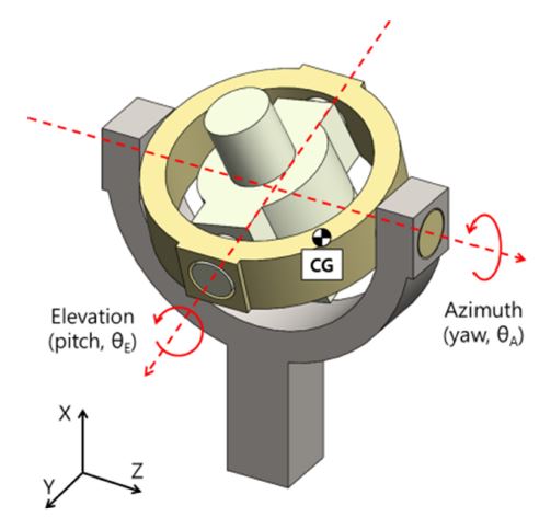
Fig. 1과 같다. 그림과 같이 짐벌은 고각(Elevation)과 방위각(Azimuth)으로 구성되며, 방위각 구동 후 고각이 구동한다. 안테나 등 기타 구성품은 고각 내부에 설치되며, 질량 불균형이 존재할 경우 외란은 2축 모두 작용한다.
Fig. 1 General type of gimbal with dual axis
앞선 설명을 통해 직구동 짐벌의 필요성 및 질량 불균형의 제어를 설명하였다. 최근 연구에서는 십 kg급 짐벌의 구동부 움직임에 따른 무게중심 변화를 1.0 g 이하의 오차로 측정하여, 질량 불균형의 값을 물리적으로 보상함으로써 외란 토크의 근본적인 원인을 제거하는 방식이 적용되었다. 그에 따라 기존에는 명확하게 구분 혹은 식별되지 않았던 현상이 확인되었다.
짐벌은 운용환경에 따른 제어 성능 검증이 필요하다. 환경조건 중 진동/충격 구조시험의 경우 짐벌 질량 불균형 보상에 따른 외란 토크 감소를 직관적으로 확인할 수 있다. 하지만 가속도 시험 시 질량 불균형 보상 결과와 무관하게 외란 토크가 발생함을 확인하였다. 기존 연구에서는 가속도 환경에 의한 질량 불균형 외란 토크가 모터 성능의 40% 이상으로 설계되었다. 따라서 짐벌 케이블 및 기타 비선형성과 가속도 시험에 따른 오차를 고려할 때 이를 명확하게 구분하기 어려운 부분이 있었다. 하지만 질량 불균형 토크가 모터 성능 대비 10% 이하로 보상되었음에도 외란 토크의 크기가 감소하지 않는 현상이 식별되었다.
본 논문에서는 원심가속시험을 통한 가속도 시험에서 발생하는 외란 토크를 두 가지로 분류/분석하여, 질량 불균형의 감소에도 발생하는 외란 토크를 규명하였으며, 이를 이론으로 예측 및 수치해석을 통해 검증하였고, 최종적으로 시험 결과와 비교하였다. 본 연구를 통해 가속도 시험 간 발생하는 외란 토크의 종류 및 크기를 고려한 설계 기준을 얻을 수 있었다. 더 나아가 외부 환경 조건에 대해 유리한 짐벌 설계 및 배치에 대한 지침을 제시하였다.
2. 원심력 외란 토크 분석 및 검증
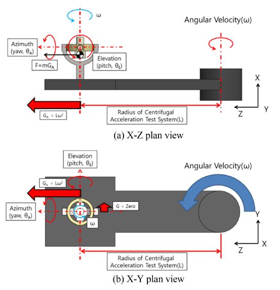
Fig. 2는 2축 짐벌의 원심가속시험을 모사한 그림이다.
Fig. 2(a)와 같이 짐벌의 중심에는 원심가속시험기의 회전중심과 같은 각속도로 회전하는 효과가 발생하며, 이는 고각과 방위각의 구동부 모두에 작용한다. 원심가속시험기 회전 시 시험기의 회전 중심으로부터 L만큼 떨어진 위치의 짐벌에 가속도 G
A가 Z축 방향으로 작용한다. 그런 반면에 시험기 회전중심과 짐벌의 Y축 방향 거리는 0이다. 따라서 Y축 방향 가속도는 0이다. 따라서 가속도는 고각 구동부의 회전에 작용한다.
Fig. 2 Centrifugal acceleration test system with gimbal

2.1 원심가속시험에 의한 짐벌 외란 토크의 발생
Fig. 3은 가속도를 받는 환경에서의 고각 구동부이다. 고각 구동부의 중량은 M
E이며 무게중심의 위치는 회전중심으로부터 H만큼 떨어져 있다.
Fig. 3Elevation part of gimbal with unbalanced mass
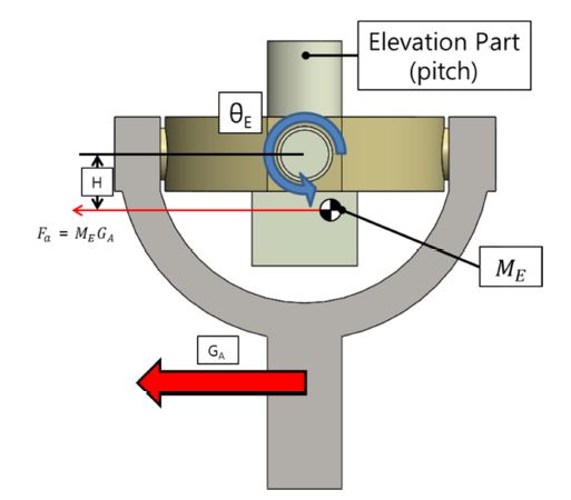
식(1)은 모터 구동에 필요한 토크이다. K는 축 또는 케이블 등의 비틀림 강성, B는 점성마찰계수, I
yy는 고각 구동부의 관성 모멘트, τ
a는 가속도에 의한 질량 불균형 토크이며, 그 값은 F
aH이다. τ
etc는 기타 외란 토크를 의미하고, 특별한 경우가 아니라면 그 값은 0이다. K, B가 0이고 짐벌이 정지된 상태라고 가정하면 모터 토크는 τ
M–τ
a이다. 따라서 질량 불균형의 감소는 모터 토크 감소로 이어진다. 실제 진동/충격 시험 시 질량 불균형 보상 이후 외란 토크가 현저히 감소하는 것을 확인할 수 있다. 하지만 원심가속시험 시 τ
a의 감소 여부와 상관없이 짐벌의 각도를 0도로 회전시키는
식(2)와 같은 토크 τ
etc가 발생함을 확인하였다.
2.2 원심가속시험에 의한 짐벌 외란 토크 유도
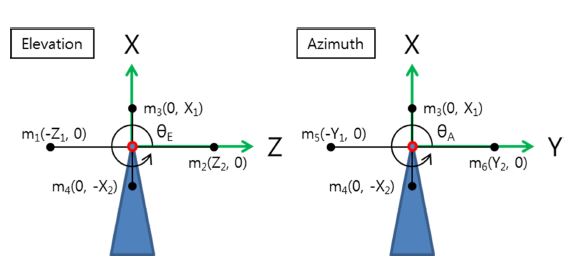
Fig. 2의 2축 짐벌 고각과 방위각을
Fig. 4와 같이 각각 1축 짐벌로 단순화하여 분석하였다. 두 모델의 물리적인 차이는 원심가속시험기의 회전중심과 짐벌의 회전축 간 거리에 따른 가속도 작용 여부이다. 짐벌은 4개의 질점으로 구성되며, 질점 1, 2, 5, 6은 수평 방향의 질량 불균형을 상징하고, 질점 3, 4는 수직 방향의 질량 불균형을 상징한다. 짐벌의 질량 불균형이 0일 때 m
1Z
1 = m
2Z
2, m
3X
1 = m
4X
2, m
5Y
1 = m
6Y
2이다. 원심가속시 험기에 의한 원심력 가속도의 크기는
식(3)과 같다. 이때 R
C, ω, A
C는 각각 시험기의 회전반경, 각속도, 원심력 가속도이다.
Fig. 4Simplified gimbal with 4 points mass

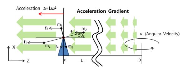
Fig. 5는 고각 구동부의 단순화 모델이다. 고각 구동부의 회전축과 원심가속시험기의 회전중심은 Z축 방향으로 L만큼 떨어져 있다. 따라서 짐벌의 회전축에는 Lω
2의 가속도가 작용하고 있다. 짐벌의 각 질점과 원심가속시험기의 회전반경은 동일하지 않으며, 각 질점에는 회전반경에 비례한 가속도가 작용하고 있다. 짐벌 각도 θ
E ≠ 0일 때 각 질점에 작용하는 원심력에 의하여 τ
a + τ
etc ≠ 0인 상태가 된다. 이때 수평 방향의 질량 불균형 성분 m
1과 m
2에는 각각 m
1(L + Z
1cosθ
E)ω
2, m
3(L + Z
2cosθ
E)ω
2의 원심력이 작용하며, 토크 τ
1, τ
2를 유발한다. 짐벌의 수평 방향성분에 의한 외란 토크 τ
H는 τ
1, τ
2의 합이다. 이를 질량 불균형과 가속도에 의한 외란 토크의 항(이하 질량 불균형 토크 항)τ
H,U와 관성모멘트 항 τ
H,I로 정리할 수 있다.
Fig. 5Centrifugal acceleration test model of Simplified gimbal (Elevation) with 4 points mass
수직 방향 질량 불균형 성분에 의한 토크 τ
V도 같은 방법으로 유도할 수 있다. 따라서 원심가속시험 중 고각 구동부에 작용하는 외란 토크 τ
ME는
식(12)와 같이 정리된다.
따라서 짐벌의 원심가속시험 시 가속도에 의한 질량 불균형 토크 τa와 짐벌 회전에 의한 τetc가 동시에 작용함을 알 수 있다. 이후 τetc를 원심력 외란 토크 τc로 정의한다.
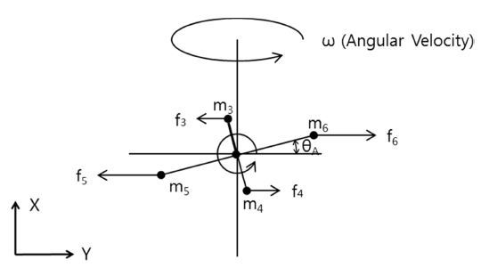
방위각 구동부에 작용 외란 토크를
Fig. 6과 같이 단순화된 모델로 수행하였다. 방위각 구동부의 회전축과 원심가속시험기의 회전중심 간 Y축 방향 거리 L = 0이다. 따라서 앞서 유도된
식(4)와
식(9)의 값은 0이며, 방위각 구동부의 원심력 외란 토크는
식(15)와 같이 정리할 수 있다.
Fig. 6Central rotation model of simplified gimbal (Azimuth) with 4 points mass
짐벌 질량 불균형이 0일 때 이다. τ
a = 0 따라서
식(12)와
식(15)는 동일한 결과를 갖는다.
2.2절을 통해 원심력 외란 토크 τ
c의 발생에 대해 알 수 있었다. τ
c는 구동부의 관성모멘트에 영향을 받으며, 크기는 관성모멘트의 수평/수식 성분의 차에 비례한다. 이후 이 관성모멘트 성분을 원심력 관성모멘트 I
C로 정의하며,
식(16)을 통해 구할 수 있다.
식(16)의 V는 수식 축을 의미하며, H는 수평 축을 의미한다.
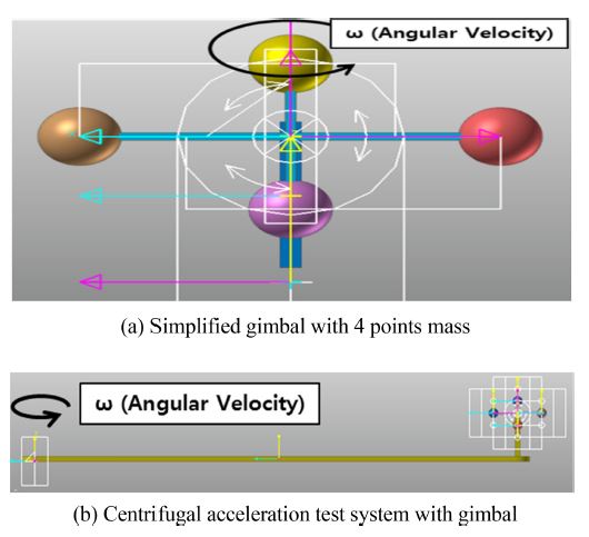
Figs. 7의 두 짐벌
7(a), 7(b)의 구동부 중량은 2배 차이가 나지만 XY 좌표계 기준 회전 관성모멘트와 원심력 관성모멘트는 같으며, 질량 불균형은 0이다.
Fig. 7Gimbals with the same moment of inertia at global coordinate system
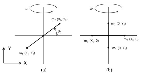
2.2절 연구에 의하면 두 짐벌은 동일한 거동을 보여야 하지만 두 짐벌의 거동은 같지 않다. 짐벌
Fig. 7(a)의 구동부 주관성 축과 XY 좌표계가 θ
c만큼 틀어져 있기 때문이다. 주관성 축을 기준으로 분석할 경우 두 짐벌의 회전 관성모멘트는 같지만, 원심력 관성모멘트 및 초기 각도는 달라지게 되며 별도의 거동을 갖게 된다. 최종적으로
식(14)에 원심력 관성모멘트와 주관성 축 각도를 반영하여
식(17)을 도출하였다. 이때 θ는 짐벌 구동각도를 의미하며, θ
0는 짐벌 구동각도 0도 기준 주관성 축각도를 의미한다.
그림과 같이 단순한 모델은 주관성 축과 짐벌 좌표계가 같지 않음을 직관적으로 알 수 있다. 하지만 질점이 많거나 복잡한 3차원 형상은 프로그램을 통해 회전/원심력 관성모멘트 및 주관성 축을 확인해야 한다. 특히 실제 2축 이상 짐벌의 경우 복합적인 구동 때문에 관성모멘트 및 주관성 축이 변경되기 때문에 이에 관한 추가적인 연구가 필요하다.
2.4 원심력 외란 토크 검증
원심력 외란 토크의 검증을 리커다인(RecurDyn)으로 진행하였다. 해석의 상세 정보는
Table 1과 같으며,
Fig. 8과 같이 외란 토크 검증모델을 구성하였다. 단순화 짐벌 모델을
Figs. 8(a)와 같이 반영하였으며, 원심가속시험을
8(b)와 같이 모사하였다. 짐벌의 회전 관성모멘트는 I
R이다. 짐벌 초기 각도 30도, 초기 각 속도 0 deg/s 조건으로 해석한 결과 짐벌에 -25.33 rad/s
2의 각 가속도가 작용하였다.
식(1)에서 모터의 구동이 없고, K, B가 0인 짐벌의 토크는
식(18)과 같이 정리되며, 질량 불균형이 0이기 때문에 τ
a = 0이다.
Table 1Analysis conditions
Table 1
|
Weight of mass [kg] |
0.2681 |
|
Horizontal distance of the point [m] |
0.05 |
|
Vertical distance of the point [m] |
0.1 |
|
Moment of inertia (IR) [kg-mm2] |
6,873.6 |
|
Centrifugal moment of inertia (IC) [kg-mm2] |
-4,021.2 |
|
Velocity of central rotation (ω) [rad/s] |
10 |
|
Initial angle of gimbal [deg] |
10-40 |
|
Distance between gimbal/rotational center [m] |
2.0 |
Fig. 8Verification model of centrifugal disturbance torque

외란 토크 τ
c의 해석결과는 174.108 N-mm 이며, 이론값은 174.123 N-mm이다. 두 결과의 오차는 0.01% 이하이며 수치해석 과정에서 발생한 오차로 판단된다. 추가적인 각도를 해석한 결과와 이론값을 비교하여
Table 2에 정리하였다.
Table 2Comparison of theoretic/numerical results
Table 2
|
Initial angle [deg] |
10 |
20 |
30 |
40 |
|
Theoretic results [N-mm] |
-68.8 |
-129.2 |
-174.1 |
-198 |
|
Numerical result [N-mm] |
-68.8 |
-129.2 |
-174.1 |
-198 |
3차원 형상 짐벌의 외란 토크 검증을
Table 3과 같이 진행하였다.
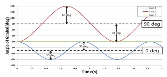
식(18)을 통한 이론값과 해석 결과의 오차는 0.04% 이하이며, 추가로 관성모멘트에 따른 3가지 짐벌의 거동을
Fig. 9와 같이 나타내었다. Cases 1과 2의 구동부의 형상은 같다. 하지만 기준 각도는 90도 차이 나도록 설치되어있다. Case 3의 구동부는 수직/수평 길이를 동일하게 하여, I
C 값이 0이 되도록 설정하였다. Case 1과 같이 I
C < 0인 경우 외란 토크는 0도 방향으로 작용한다. Case 2와 같이 I
C > 0 경우 외란 토크는 90도 방향으로 작용한다. Case 3과 같이 I
C = 0 경우 외란 토크는 0이다.
Table 3Analysis conditions for 3D gimbal model
Table 3
|
Case 1 |
Case 2 |
Case 3 |
|
Size [mm] |
200 × 100 × 20 |
100 × 200 × 20 |
200 × 200 × 20 |
|
Weight [kg] |
3.14 |
3.14 |
6.28 |
|
IR [kg-mm2] |
13,083 |
13,083 |
41,867 |
|
IC [kg-mm2] |
-7,850 |
7,850 |
0 |
|
Velocity of central rotation (ω) [rad/s] |
10 |
10 |
10 |
|
Initial angle [deg] |
30 |
30 |
30 |
|
Angular acceleration (θ¨) [rad/s2] |
-25.97 |
25.97 |
0.00 |
|
Theoretic results τC [N-mm] |
-339.9 |
339.9 |
0 |
|
Numerical result τC [N-mm] |
-339.7 |
339.7 |
0 |
Fig. 9Numerical result of angle
3. 질량 불균형 외란 토크 분석 및 검증
3.1 질량 불균형 외란 토크의 유도
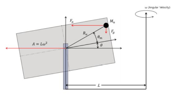
본 절에서는 실제 짐벌과 같이 질량 불균형이 0이 아닐 때 작용하는 외란 토크를
Fig. 10과 같은 모델로 분석하였다. 분석 모델의 질량 불균형 질량은 M
u이며, 짐벌 구동부 회전중심으로부터 R
u만큼 떨어져 있다. M
u는 짐벌 구동부의 주관성 축을 기준으로 θ
m만큼 기울어져 있다. M
u에는 원심가속시험기의 회전에 의한 가속도 하중(원심력) F
a와 중력가속도 하중 F
G가 작용하며, M
u에 의한 질량 불균형 외란 토크는
식(23)과 같다.
Fig. 10Centrifugal acceleration test model of gimbal with unbalanced mass
짐벌에 작용하는 총 외란 토크는
식(23)과 같다.
식(23)에 대한 검증을 수치 해석으로 진행하였다. 이때 추가로 가속도에 따른 짐벌의 외란 토크 차이를 분석하기 위해 회전반경을 0과 L 두 가지로 적용하였으며, 상세정보는
Table 4에 나타내었다. 질량 불균형은 500 gf-mm를 반영하였다. 이는 기구물의 설계 결과에 따라 발생 가능한 수준이며, 이를 보상하지 않은 상황을 가정하여 분석을 수행하였다.
Fig. 11은 해석 결과이다. 짐벌의 초기 각도는 30도이며, 해석 결과 Cases 1과 2의 초기 각 가속도 -26.3과 -20.5 rad/s
2가 얻어졌다. 이를
식(19)와
(24)로 계산하여 비교하여
Table 4에 나타내었다. 두 결과가 일치함을 통해
식(23)을 검증할 수 있었다. 원심가속시험기의 회전 각속도가 같고 회전반경이 0과 L인 짐벌 외란 토크를 비교하여
식(25)와 같이 질량 불균형에 의한 외란 토크를 구할 수 있다.
Table 4Analysis conditions for 3D gimbal with unbalanced mass
Table 4
|
|
Case 1 |
Case 2 |
|
Gimbal |
Size [mm] |
200 × 100 × 20 |
200 × 100 × 20 |
|
Weight [kg] |
3.14 |
3.14 |
|
IR [kg-mm2] |
13,083 |
13,083 |
|
IC [kg-mm2] |
-7,850 |
-7,850 |
|
Θ [deg] |
30 |
30 |
|
Unbalanced mass |
Mu [kg] |
0.005 |
0.005 |
|
Ru [mm] |
100 |
100 |
|
θm [deg] |
20 |
20 |
|
IR [kg-mm2] |
50 |
50 |
|
Test conditions |
L [mm] |
0 |
2,000 |
|
ω [rad/s] |
10 |
10 |
|
Theoretic results |
τ [N-mm] |
-345.4 |
-268.9 |
|
Numerical result |
τ [N-mm] |
-345.5 |
-268.9 |
Fig. 11Angle and Angular acceleration of gimbal with unbalanced mass (Initial angle of θ = 30 deg)
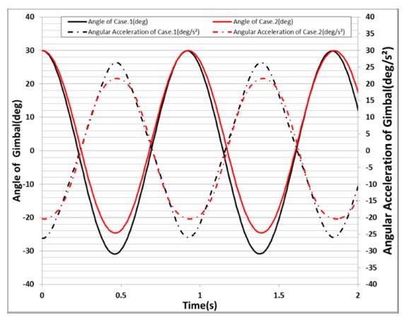
Cases 1과 2의 외란 토크의 차이는 76.6 N-mm이며,
식(25)를 통해 동일한 값을 계산할 수 있다.
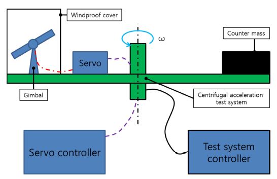
4. 짐벌 외란 토크 검증시험
실물 짐벌의 가속도 시험을
Fig. 12와 같이 구성하여 수행하였다. 원심가속시험의 회전으로 발생한 공기 유동에 의한 토크를 발생 방지하기 위한 덮개를 설치하였으며, 장비의 각속도 안정화 후 짐벌을 구동에 사용된 토크를 이론값과 비교하였다. 외란 토크 예측에 필요한 관성모멘트는 실물이 반영된 3차원 형상으로 계산하였다. 짐벌의 질량 불균형은 밸런싱장비를 통해 10.0 gf-mm 이하로 보상하였다. 이는 실제 모터 구동토크 대비하여 0.1% 이하이다. 따라서 질량 불균형과 가속도에 의한 토크는 무시 가능한 수준으로 판단된다.
Fig. 12 Angular acceleration test of gimbal

Fig. 13은 시험과 이론값의 비교 결과이다. 5-25도 구동 시 소요된 토크와 이론값 간 최대 오차는 4.5% 이하이며 이는 3차원 모델에 반영되지 않은 케이블 등 기타 비선형 요소에서 발생한 오차로 판단된다. 가속도 시험 시 짐벌은 최대 구동 각도 이하의 성능으로 구동하였다. 짐벌의 최대 운용 각도 성능은 25도 이상이다. 하지만 짐벌의 각도가 25도 이상일 때 외란 토크의 크기가 모터 성능을 초과하여 추가적인 구동이 불가능함을 확인하였다.
Fig. 13 Normalized result of test and analysis
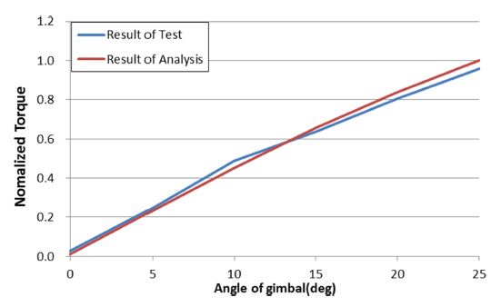
본 연구에 사용된 실물 짐벌의 경우
식(23)을 통해 분석한 결과 τ ≅ τ
C로 판단된다. 따라서 원심가속시험 중 모터 성능 초과는 설계요인보다 환경시험 구현 방식의 문제로 판단된다. 직선가속도만 작용할 경우 모터 성능 초과는 발생하지 않으리라고 판단된다. 이전 연구에서 짐벌의 질량 불균형 외란 토크는 모터 성능의 40% 이상이었다. 따라서 τ
C와 τ
U의 명확한 구분과 분석에 어려운 점이 있었다. 특히 질량 불균형에 의한 주관성 축의 변화가 분석을 더 어렵게 만들었다. 본 시험에서는 밸런싱장비를 통해 짐벌의 질량 불균형 외란 토크를 모터 성능의 0.1% 이하로 감소시켜 분석에 필요한 변수를 최소화하였으며, 이론과 비교함으로써 실제 운용환경과는 다르게 시험 방안에 따라 발생할 수 있는 원심력 외란 토크를 확인하였다.
5. 활용
본 연구를 통해 플랫폼이 회전하는 환경에서 I
C에 의해 토크가 발생하는 것을 확인하였다. 실제 플랫폼의 운용환경이 회전하지 않을 경우 원심가속시험에서 발생한 원심력 외란 토크를 배제하여 모터 과설계를 방지할 수 있다. 원심가속시험기의 가속도는 Lω
2에 비례하며, 원심력 외란 토크는 ω
2에 비례한다. 따라서 같은 가속도 시험이라도 시험기의 회전반경이 두 배일 경우 원심력 외란 토크를 50%로 줄어든다. 만약 물리적인 원심력 외란 토크 저감이 어려울 경우
식(17)을 통해 원심력 외란 토크를 예측하고 이를 설계에 반영하는 것이 가능하다.
플랫폼이 회전하는 특별한 경우 본 연구를 활용할 수 있다. 1축 짐벌과 달리 2축 짐벌은 상대 구동부의 운용각도에 따라 I
C가 변경된다. 따라서 I
C가 0이 되는 안전모드 각도 제어가 가능하다. 이러한 안전모드를 전체 운용 구간에 적용하기엔 어려운 부분이 있다. 하지만 설계변경 없이 짐벌을 표적 근접거리까지 안정적으로 운반할 수 있다는 점이 장점이다. 이때 2축 짐벌의 자세에 따른 I
C의 분석을
식(16)을 통해 진행할 수 있다. 만약 표적의 추적 등을 포함한 전 운용 구간에서 짐벌이 과도한 회전에 노출될 경우 각 구동부의 I
C는 0이 되도록 설계되어야 한다. 짐벌 구동부의 관성모멘트는 짐벌 제어에 중요한 변수이다. 기존에는 이를 서보 제어에 필요한 전류를 분석하여 예측하였다. 전류를 통한 측정방식은 오차가 포함될 수 있다. 만약 짐벌의 구동축 관성모멘트 중 1축 이상 정확한 관성모멘트를 알고 있을 때
식(17)과 외란 토크 τ
C를 통해 I
C를 계산하고 각 축의 관성모멘트를 구할 수 있다.
6. 결론
본 논문에서는 타 구조시험과 달리 가속도 시험에서 질량 불균형의 크기와 무관하게 발생하는 외란 토크를 이론으로 예측 및 검증하였다. 일반적으로 가속도 시험은 방법의 효율 문제로 원심가속시험 방안으로 수행된다. 원심가속시험은 시험물의 회전을 통한 원심력을 이용하기 때문에 질량 불균형 외란 토크와 원심력 외란 토크가 동시에 발생된다. 따라서 실제 운용환경에서는 존재하지 않는 원심력 외란 토크에 의한 과도한 설계를 방지하고자 시험기의 회전반경을 증가시켜 외란을 줄이는 방법과 외란의 크기를 예측하여 모터 설계에 반영하는 것에 관한 연구가 진행되었다.
본 연구를 통해 원심력 외란 토크가 시험기의 회전반경과 각 속도, 그리고 짐벌 원심력 관성모멘트에 영향받음을 이론과 해석, 시험을 통해 정량적으로 비교하고 증명할 수 있었다. 본 연구를 통해 도출된 원심력 외란 토크 이론을 짐벌 설계에 반영함으로써 고기동 플랫폼에 요구되는 환경조건에 최적화된 모터 설계가 가능할 것으로 판단된다. 또한 고기동 플랫폼의 회전 기동 등을 가정한 짐벌의 안전 기동 모드적용을 검토에 필요한 근거로 활용 및 평가에 반영하여 개발 품질을 확보할 수 있다고 판단된다.
ACKNOWLEDGMENTS
본 연구는 주관기관인 국방과학연구소의 사업을 통해 진행되었습니다.
REFERENCES
- 1.
Baek, J., Kwak, Y. K., Kim, S., (2003), Backlash estimation of a seeker gimbal with two-stage gear reducers, The International Journal of Advanced Manufacturing Technology, 21(8), 604-611.
10.1007/s00170-002-1378-z
- 2.
Lim, J.-K., Choi, Y.-J., Lyou, J., Seok, H.-D., Kim, B.-U., Kang, M.-S., (2005), Adaptive disturbance compensation control for heavy load target aiming systems to improve stabilization performances, Transactions of the Korean Society for Noise and Vibration Engineering, 15(11), 1303-1310.
10.5050/KSNVN.2005.15.11.1303
- 3.
Yeo, S., Park, T., Kang, M., (2017), Feedforward compensation of mass unbalance torque for 2-DOF gimbal system, Proceedings of the Korean Society for Precision Engineering 2017 Autumn Conference, 369-370.
- 4.
Kang, M.-S., Cho, Y.-W., (2010), Stabilization control of line of sight of OTM (On-the-move) antenna, The Transactions of the Korean Institute of Electrical Engineers, 59(11), 2073-2082.
- 5.
Yeo, S. M., Kang, M. S., (2018), A simultaneous experimental disturbances identification of gyro stabilized 2-axes gimbal system for disturbance feedforward compensation control, Journal of the Korea Institute of Military Science and Technology, 21(4), 508-519.
- 6.
Mu, Q., Liu, G., Zhong, M., Chu, Z., (2012), Imbalance torque compensation for three-axis inertially stabilized platform using acceleration feedforward, Proceedings of the IEEE 2012 8th International Symposium on Instrumentation and Control Technology (ISICT), 157-160.
10.1109/ISICT.2012.6291627
- 7.
Mao, W., Liu, G., Li, J., Liu, J., (2016), An identification method for the unbalance parameters of a rotor-bearing system, Shock and Vibration, 2016, 8284625.
10.1155/2016/8284625
Biography
- Jun Soo Kim
Research Engineer in LIG Nex1 Co., Ltd.. His research interest is mechanical engineering.
- Dong-Kyun Lee
Research Engineer in LIG Nex1 Co., Ltd.. His research interest is mechanical engineering.
- Suk-In Lee
Research Engineer in LIG Nex1 Co., Ltd.. His research interest is linear system design.
- Hyeon-Jun Cho
Research Engineer in LIG Nex1 Co., Ltd.. His research interest is mechanical engineering.
- Moon-Young Yoon
Research Engineer in Agency for Defense Development. His research interest is linear system design.