ABSTRACT
This paper presents an improved formulation, to estimate the sliding friction torque of deep groove ball bearings (DGBBs). Running torque of rolling element bearings, is directly associated with heat generation in rotating machines. Among the components of running torque, sliding friction is a major friction source in ball bearings. For DGBBs, sliding friction is dominated by spinning and differential sliding between balls and races. This paper addresses the sliding friction torque components of DGBBs: Spinning friction, differential sliding friction due to the ball rotation, and differential sliding friction due to the ball orbital motion. An efficient and accurate computational method is proposed for the individual sliding friction sources, based on pure rolling lines in the elliptical contact area between the balls and races. The proposed method applies an updating algorithm, for estimating more accurate information about the pure rolling lines. The proposed method was validated in terms of comparison with other methods, and with the empirical formulae provided by a bearing manufacturer. Simulations were also conducted to investigate the impacts of important parameters on the sliding friction torque in DGBBs.
-
KEYWORDS: Deep groove ball bearing, Angular contact ball bearing, Sliding friction torque, Differential sliding friction, Spinning friction, Pure rolling lines
-
KEYWORDS: 깊은 홈 볼베어링, 각접촉 볼베어링, 미끄럼 마찰토크, 차동 미끄럼마찰, 스피닝 마찰, 순수구름선
NOMENCLATURE
Work Done per Unit Time of a Ball by Differential Slippage, Nmm/min
Semi-Major Radius of the Elliptical Contact Area, mm
Semi-Minor Radius of the Elliptical Contact Area, mm
Pure Rolling Line Locations
Bearing Outer Diameter, mm
Bearing Bore Diameter, mm
Bearing Pitch Diameter, mm
Geometrical Parameter Associated with c-values
Ratio of the Net Sliding Friction Force to the Maximum Sliding Friction Force
External/Equivalent Force, N
Sliding Friction Force, N
External Load Vector, N, Nmm
Distance Traveled per Unit Time, mm/min
External/Equivalent Moment, Nmm
Differential Sliding Friction Torque due to Ball Orbital Motion, Nmm
Differential Sliding Friction Torque due to Ball Rotation, Nmm
Spinning Friction Torque, Nmm
Sliding Friction Torque, Nmm
Gyroscopic Moment at y’-direction, Nmm
Gyroscopic Moment at z’-direction, Nmm
Moment due to Ball Rotation, Nmm
Inner Ring Rotational Speed, rpm
Sliding Velocity at the x”-direction of Elliptical Contact Area, mm/s
Sliding Velocity at the y”-direction of Elliptical Contact Area, mm/s
Angle Associated with Differential Sliding Friction, rad
Displacement Vector, mm, rad
Angle Associated with the Elliptical Contact Area
Sliding Friction Coefficient
Complete Elliptic Integral of the Second Kind
Angle Associated with the Velocities in the Elliptical Contact Area, rad
Angle Associated with the Implicit Calculation of c-values, rad
Ball Rotational Speed, rad/s
Ball Pivotal Speed, rad/s
Elliptical Contact Area Coordinates
SUBSCRIPTS
1. Introduction
Heat generation in rolling-element bearings has been a crucial issue for a very long time. It is well known that the running torque, resulting from the internal friction by rolling-element bearings, is directly associated with heat generation in rotating machines [
1,
2]. Such internal friction by the rolling-element bearings has a significant contribution to power loss which is an important factor for machine efficiencies [
3,
4]. There are several components of running torque that is liable for the heat generation of rotating machines such as elastohydrodynamic lubrication (EHL) friction, friction due to elastic hysteresis, sliding friction, friction due to drag losses, and friction due to sealing [
5,
6]. Among these, the sliding friction torque that is related to the ball sliding between the balls and races is acknowledged as one of the most important components.
Sliding friction arises due to the contact conformity, the spinning effect, and the elastic deformation in the contact area [
6]. The individual sources of friction in rolling-element bearings should be calculated independently [
7]. There are two independent friction sources between the balls and races: the sliding friction due to differential speed that is formed by elastic deformation in the ball-race contact region and the friction due to the spinning motion of the ball relative to the races [
8].
Many researchers proposed estimation methods for sliding friction torque in rolling-element bearings. Kakuta [
9] proposed analytical formulae for both spinning and differential sliding friction torque in radial ball bearings under pure axial load. In his study, the spinning motion was assumed to occur only in one race. He estimated the sliding friction force as a function of pure rolling line (PRL) locations. However, his study did not consider the unsymmetrical aspect of PRLs. Kanatsu and Ohta [
10] presented both spinning and differential sliding frictions in a deep groove ball bearing under pure axial load. They proposed spinning and differential sliding friction formulae without taking advantage of PRLs. Wang, et al. [
11] performed a similar study to examine the friction torque of a DGBB under pure radial load. Tong and Hong [
12,
13] improved the differential sliding and spinning friction formulations for the running torque prediction of angular contact ball bearings (ACBBs). They utilized constant PRL locations to estimate sliding friction torque all over the speed range with an assumption that PRLs are symmetrically positioned from the center of the elliptical contact area.
Houpert [
14] presented a new formulation to estimate friction forces from the summation of sliding moment forces acting on individual balls. The sliding moments were estimated first using curve-fitted results and then PRL locations were obtained. However, the PRLs did not reflect the effects of centrifugal force and gyroscopic moment. Popescu, et al. [
15] applied Houpert’s method to estimate the power loss of ACBBs. Rivera, et al. [
16] investigated the sliding motions on ball-race contacts by employing Houpert [
14] and Popescu’s method [
15]. They presented results that PRL locations are dependent on bearing parameters such as contact angles, rotational speed, and loading conditions.
This paper dealt with the estimation of sliding friction torque. To this end, sliding friction torque has been investigated with detailed sliding friction components: Spinning friction torque, differential sliding friction torque due to ball rotation, and differential sliding friction torque due to ball orbital motion. An efficient and accurate computational method was proposed for the estimation of sliding friction torque components based on locating PRLs between the ball and races. The PRL locations were estimated through the updated c-value method by maintaining the moment and friction force equilibrium acting on individual balls.
The proposed method was compared with other methods. Moreover, the proposed method was validated in terms of comparison with the empirical formulae provided by a bearing manufacturer [
6]. Additional simulations were carried out to examine the effects of several important parameters on the sliding friction torque of DGBBs. The proposed method can also be used for ACBBs, which have non-zero nominal contact angles.
2. Mathematical Modeling of Sliding Friction Torque
This section describes the analytical formulation for sliding friction torque in DGBBs. Sliding friction torque in a DGBB is mainly caused by the ball motions relative to the raceways when the balls are spinning and rolling. To estimate the sliding friction torque, the torque of an individual ball needs to be determined and then summed up over the number of balls in the DGBB. Thus, the expression of the sliding friction torque, Msl, is written by:
where
Ms,
Mr, and
Md are the spinning, the differential sliding friction torque due to ball rotation, and the differential sliding friction torque due to ball orbital motion, respectively. To find sliding friction forces, several dynamical quantities of the bearing are needed such as contact forces, contact angles, and dimensions of contact ellipses formed between balls and races. These quantities can be estimated by using the quasi-static model of ACBB [
17-
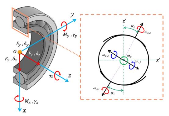
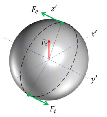
19]. A DGBB may be subjected to 5-DOF loading as shown in
Fig. 1, where the loading and displacement vectors are represented by {
F}
T = {
Fx,
Fy,
Fz,
Mx,
My}, and {
δ}
T = {
δx,
δy,
δz,
γx,
γy}, respectively.
n is the rotational speed of the inner ring in rpm and
αk is the contact angle.
Fig. 1 Global coordinate system and ball motions in a DGBB

2.1 Spinning Friction Torque
Spinning motions (
ωs,k) about the normal direction to the center of the contact ellipse occur between balls and races as shown in
Fig. 1. Spinning moment is defined as the moment of friction about the center of the contact ellipse as follows [
16,
20]:
where
k =
i,e denotes the inner and outer races, respectively.corresponds to the sliding friction coefficient based on an SKF model [
6] and
Qk is the ball contact load.
ak,
bk are the major and minor radii of the contact ellipse.
θk,
ϕk and are expressed as
Here,
ωs, k is the ball’s pivotal speed and
vx,k,
vy,k are the sliding velocities in the elliptical contact area between a ball and races [
16,
20].
Several authors have suggested an equation to calculate the spinning moment when the motion of a race relative to the ball is purely spinning, i.e.
θk =
ϕk [
9,
10,
20-
22]. Then
Eq. (2) becomes
where ξk is the complete elliptic integral of the second kind, with modulus 1-bk2/ak20.5. Here, the ball only spins on one race and rolls on both races.
The spinning moment can also be estimated as a function of PRL locations as follows [
14-
16]:
i) 1-PRL case,
ii) 2-PRL case,
where
c1k and
c2k are the first and second PRL locations, respectively. Then the friction torque due to spinning is written as [
12,
13,
16]
where j and Z represent the ball location number and the number of balls, respectively.
2.2 Differential Sliding Friction Torque
This friction comes from the ball-race contact deformation. When such a ball-race deformation occurs, pure rolling can be found in two lines at most within a certain distance from the ellipse center. These lines are called PRLs that are associated with the sliding velocity between the ball and races in the elliptical contact area [
20,
23]. In regions other than the PRLs, sliding dominates due to differential slippage. The differential sliding friction in connection with differential slippage can be calculated with appropriate friction forces in the inner and outer races [
9-
13]. The friction forces are analytically derived from the double integration of net friction force in the
y’-direction (Rolling Direction) shown in
Fig. 2 as
Fig. 2Centrifugal force and sliding friction forces between ball-race contacts
i) 1-PRL case,
ii) 2-PRL case,
The two PRL locations are related as follows:
where
Rk is the Hertzian contact radius or the radius caused by deformation [
20].
2.2.1 Differential Sliding due to Ball Rotation
A ball rotation (
ωr,k) occurs simultaneously with a spinning motion (
ωs,k). This motion creates a friction moment about an axis through the ball center perpendicular to the spinning moment and rolling direction,
mr,k, as [
20]
where
Then the differential sliding due to ball rotation is given by
Here, RL,k, rk′ are the radius of the roller groove and the radius of rolling, respectively.
2.2.2 Differential Sliding due to Ball Orbital Motion
The differential sliding due to ball orbital motion (
ωm) is caused by the differential slip of the ball on the contact surface circulating the bearing center. In this case, every ball rolls along a curved groove in a plane perpendicular to the rolling direction. The work done per unit time for each ball by differential slippage can be expressed by [
9,
12,
13,
24]
where
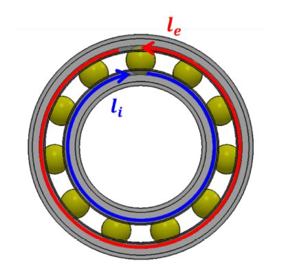
l and
le are the distances traveled per unit time by the point of ball-race contact or the slipping distance on inner and outer races, respectively, as depicted in
Fig. 3. These can be represented as
Fig. 3Distance traveled per unit time by the point of ball-race contact

It should be noted that
Eq. (18) is only valid for the case when the inner ring rotates, and the outer ring is stationary.
Then, the differential sliding friction torque due to ball orbital motion is obtained by
2.3 Updated c-value Method
The method to calculate sliding friction force in ball bearings was first proposed by Jones [
23] and later generalized by Harris [
20]. Friction forces and moments acting on each ball were represented in terms of nonlinear equations involving double integrals that require complicated calculations. Harris [
20] attempted to calculate the unknown sliding friction forces through an iteration process by maintaining the equilibrium of the frictional and gyroscopic moments acting on a ball. However, there is a limitation such that the sliding friction coefficient was assumed to be a constant (Coulomb Friction Coefficient), even though it is a complex function of several variables.
Here, a formulation for sliding friction force was proposed by improving Harris’ estimation procedure [
20] with updating
c-values introduced in
Eqs. (6)-
(11) for PRL locations. The summation of the moments in each direction must be zero, as illustrated in
Fig. 4:
Fig. 4Ball moment equilibrium
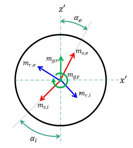
i) x’-direction
ii) z’-direction
Here, the unknown parameters are
mr,k and
ms,k.
mgz is the gyroscopic moment in the z'-direction, which may be neglected in DGBBs. Then, the summation of
Eqs. (20) and
(21) becomes
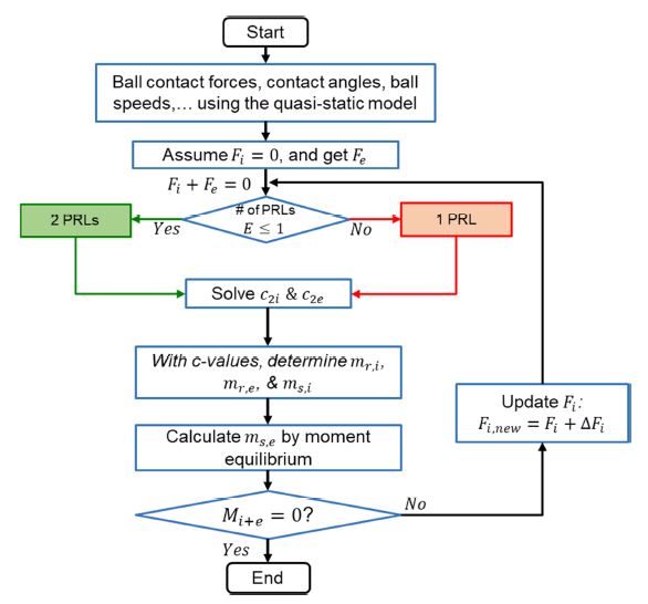
The iteration process is shown in
Fig. 5. First, a quasi-static, 5-DOF model for ball bearings [
17-
19] is used to pre-calculate important parameters such as ball contact loads, contact angles, and ball speeds. Then, as an initial guess,
Fi will be set to 0 and
Fe can be calculated from the summation of the sliding frictional moment in the y'-direction which can be expressed as
Fig. 5Calculation process for sliding friction force by the updated c-value method

This equation implies that the sliding friction force on the inner race is equal to the sliding friction force on the outer race but in the opposite direction (
Fig. 2). Obtaining both friction forces determines the
c-values. However, the number of PRLs inside the elliptical contact area must be examined. When the sliding friction force,
Fk, is small enough to satisfy
Ek ≤ 1, two PRLs exist inside the elliptical area (2-PRL Case). On the other hand, for
Ek > 1, one PRL exists inside the elliptical area while its pair lies outside (1-PRL Case) [
14-
16]. Even though three solutions for can be obtained from the 3
rd order polynomials in
Eqs. (9) and
(10), only one solution, which satisfies
c2,k ≤ 1, can be selected; This indicates that the true PRL locations must lie inside the elliptical contact area. Mathematical equations to determine
c-values can be used as follows:
i) 1-PRL case,
where
ii) 2-PRL case,
where
The parameter ek is defined as the ratio between the net sliding friction force and the maximum friction force, as follows:
Using the values obtained from
Eqs. (24) or
(26),
mr,i and
mr,e can be calculated using
Eq. (13). The spinning moment on the inner race,
ms,i, can be solved using
Eqs. (6) or
(7). Then,
Eq. (22) is used to determine
ms,e which is influenced by other factors that are not included in
Eqs. (6) or
(7).
As a final condition for this process, the input torque to an individual ball must be equal to its output torque, i.e., [
20]
The left-hand side value of
Eq. (29) is re-calculated with updating
Fi until
Eq. (29) is satisfied within a given tolerance.
3. Simulations
This section shows the model comparison, validation, and simulation result of sliding friction torque. A sample bearing DGBB 6206 is used for validation and simulation. The proposed sliding friction torque model based on the Stribeck curve is compared with a conventional model with a constant Coulomb friction coefficient. In addition, DGBBs 6207, and 6208 were also considered to validate the proposed method with different-sized DGBBs whose properties are listed in
Table 1.
Table 1 Basic parameters of investigated DGBBs
Table 1
|
Parameters |
Bearing type |
|
6206 |
6207 |
6208 |
|
Bearing bore diameter (d) [mm] |
30 |
35 |
40 |
|
Bearing outer diameter (D) [mm] |
62 |
72 |
80 |
|
Ball diameter (Da) [mm] |
9.525 |
11.12 |
12.3 |
|
Pitch diameter (dm) [mm] |
46 |
53.5 |
60 |
|
Number of balls (Z) |
9 |
9 |
9 |
3.1 Comparison of Proposed Model with Others
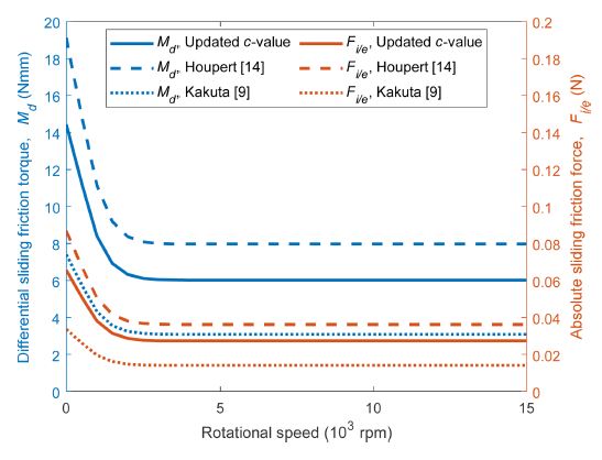
Fig. 6 compares the differential sliding friction forces and torques using the updated
c-value method and those of the Houpert method [
14] and Kakuta method [
9]. The sliding friction force (Red axis) is needed to estimate differential sliding friction torque (Blue axis). Utilizing the Houpert method [
14] shows a higher estimation of sliding friction force and torque in comparison to the updated
c-value method. On the other hand, Kakuta method [
9] shows a lower sliding friction force and torque.
Fig. 6Comparison of the proposed differential sliding friction force and torque with those of other methods under pure axial load, Fz = 500 N, DGBB 6206

Fig. 7 compares the proposed spinning friction torque with existing models. The spinning friction torque calculated using the updated
c-value method agrees well with that of Houpert method [
14] which uses curve-fitted results for the spinning moment. Both models included the effects of spinning on both races. However, the conventional method is based on pure spinning on one race only which shows a lower result in comparison to the updated
c-value method and Houpert method.
Fig. 7Comparison of existing spinning friction torque models under pure axial load, Fz = 500 N, DGBB 6206
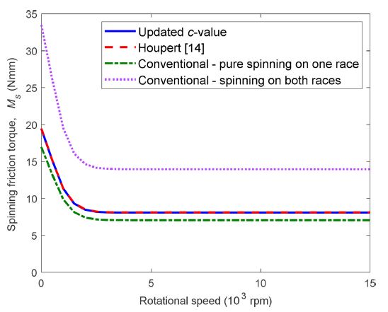
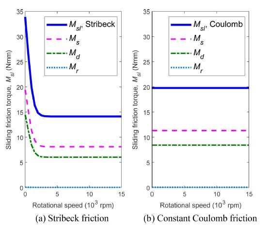
Fig. 8 shows the sliding friction torque with the effect of lubrication (Stribeck Friction) in comparison with that under constant Coulomb friction. The sliding friction coefficient under the effect of lubrication results from the shearing of oil and asperity contacts. Here, the sliding friction coefficient at low and high speeds are approximately
μ = 0.12 and
μ = 0.05, respectively. The transition of the sliding friction coefficient is determined by a weighting factor as presented in the SKF catalogue [
6]. On the other hand, the sliding friction coefficient under Coulomb friction is assumed constant all over the speed range. The sliding friction coefficient was chosen to be equal to
μ = 0.07 as recommended by Jones [
23]. In DGBBs with low centrifugal and gyroscopic effects, sliding friction torque follows the trend of its sliding friction coefficient. This figure shows that the constant Coulomb friction model differs significantly from the proposed model.
Fig. 8Comparison of sliding friction torques and components under pure axial load, Fz = 500 N, DGBB 6206
3.2 Validation and Simulation
3.2.1 Pure Axial Load
Figs. 9,
10, and
11 show the sliding friction torques under pure axial load by the proposed method and SKF empirical formula [
6]. These figures show that the proposed method agrees well with the SKF empirical formula.
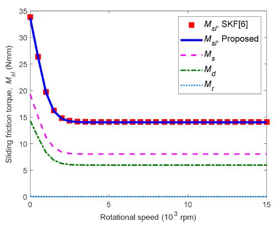
Fig. 9Sliding friction torque and components under pure axial load, Fz = 500 N, DGBB 6206

Fig. 9 shows the sliding friction torque for DGBB 6206 under a pure axial load of
Fz = 500 N. Here, spinning and differential sliding due to orbital motion dominates the sliding friction torque while the differential sliding friction torque due to ball rotation only gives a very small share of sliding under the given load.
Table 2 shows a tabulated numerical result of sliding friction torque under pure axial load at rotational speeds of 500, 5,000, and 15,000 rpm based on
Fig. 9. With the given conditions, the proposed method shows very small errors from the empirical formulas of SKF.
Table 2Numerical results of sliding friction torque and components under pure axial load, Fz = 500 N, DGBB 6206
Table 2
|
Inner ring rotational speed (n) [rpm] |
Sliding friction torque (Msl) [Nmm] |
Percentage error [%] |
|
Proposed (P) |
SKF (S) |
P-SS×100
|
|
500 |
26.4162 |
26.3645 |
0.1960 |
|
5,000 |
14.1291 |
14.1014 |
0.1960 |
|
15,000 |
14.1289 |
14.1013 |
0.1954 |
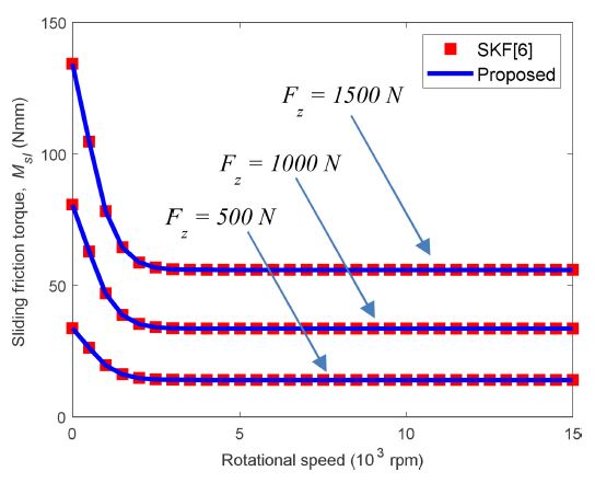
Fig. 10 shows the result of sliding friction torque for DGBB 6206 with changing axial loads of
Fz= 500, 1,000, and 1,500 N. Here, the figure clearly shows that axial load increases the sliding friction torque. With given axial loads, the centrifugal force effect does not change the sliding friction torque even at high speeds.
Fig. 10Sliding friction torque under different axial loads, DGBB 6206

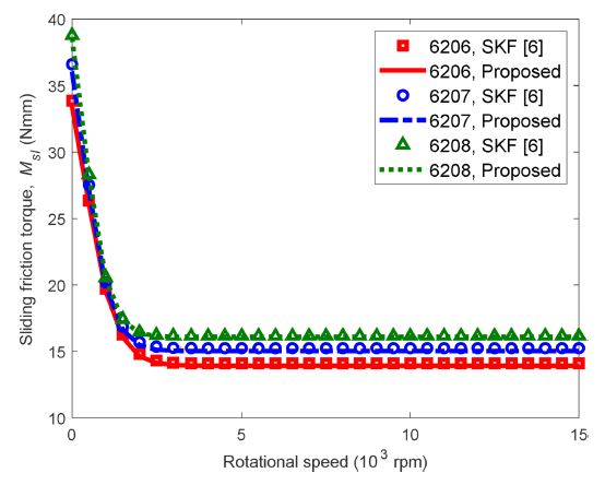
Fig. 11 portrays the results of sliding friction torque estimation for different sized DGBBs such as 6206, 6207, and 6208, of which bore diameters (
d) are 30, 35, and 40 mm, respectively. Here, all sample DGBBs have the same number of balls (
Z) as specified in
Table 1. Simulations show that sliding friction torque increases as bearing size increases for the same bearing series.
Fig. 11Sliding friction torque under pure axial load with different bearing sizes, Fz = 500 N
3.2.2 Pure Radial Load
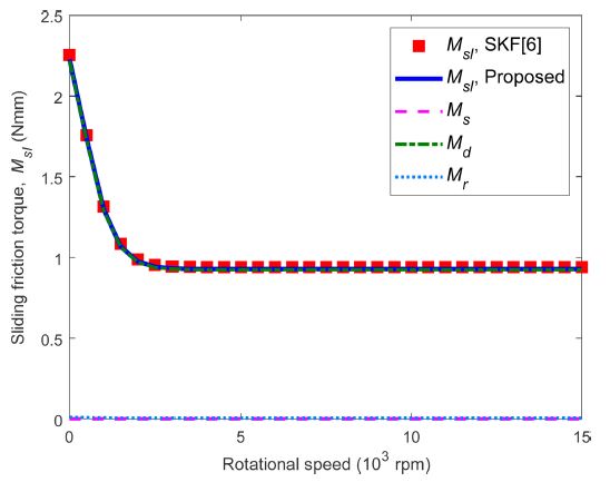
Fig. 12 shows the sliding friction torque, as well as its components under a pure radial load of
Fx = 500 N. Here, spinning friction torque vanished while the sliding friction torque due to orbital speed became the main source of sliding friction torque all over the speed range. The differential sliding friction torque due to ball rotation remained at a low magnitude. The sliding friction torque was very small compared to that under a similar amount of pure axial load. This is mainly because the contact angle becomes 0
o under pure radial load. In this case, some balls may lose contact with races resulting in the reduction of sliding friction torque.
Table 3 shows a tabulated numerical result of sliding friction torque under pure radial load. The sliding friction torque under radial load is much smaller than those under axial load. The difference between the proposed method and the SKF empirical model is reasonably small.
Fig. 12Sliding friction torque and its components under pure radial load, Fx = 500 N, DGBB 6206

Table 3Numerical results of sliding friction torque and components under pure radial load, Fx = 500 N, DGBB 6206
Table 3
|
Inner ring rotational speed (n) [rpm] |
Sliding friction torque (Msl) [Nmm] |
Percentage error [%] |
|
Proposed (P) |
SKF (S) |
P-SS×100
|
|
500 |
1.6932 |
1.7574 |
3.6504 |
|
5,000 |
0.9057 |
0.9400 |
3.6504 |
|
15,000 |
0.9056 |
0.9400 |
3.6506 |
Fig. 13 depicts the sliding friction torque with changing the pure radial load, i.e.,
Fx = 500, 1,000, and 1,500 N. The proposed method is in good agreement with the SKF empirical model. This figure also shows that increasing radial load increases the sliding friction torque. It is also observed that the sliding friction torque, which is mostly due to differential sliding friction torque, increases nonlinearly with the radial load.
Fig. 13Sliding friction torque under different pure radial loads, DGBB 6206
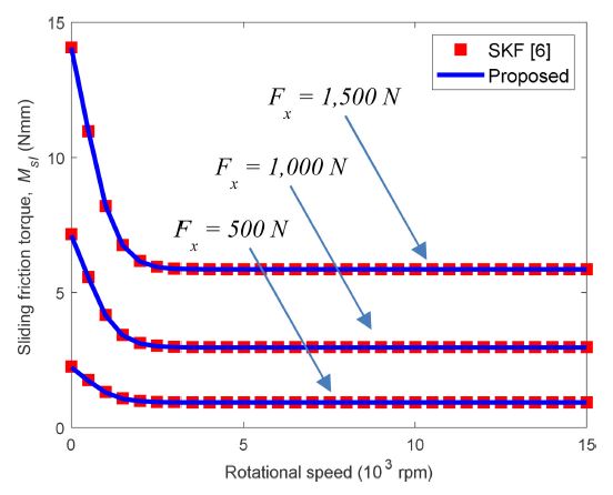
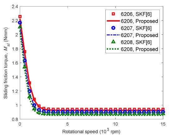
Fig. 14 shows the sliding friction torques from various DGBBs under a pure radial load of 500 N. It shows that the proposed method comes to a good agreement with the SKF empirical model with different-sized DGBBs. Unlike the pure axial load case, the sliding friction torque slightly decreases as bearing size increases. This can be explained by the definition of the differential sliding torque as a multiplication of contact load and the distance traveled per unit of time. Even though bigger bearings tend to have a longer distance traveled per time, they have lower contact loads than smaller ones. Then multiplication of these two elements makes the differential sliding friction torque may decrease under the same radial load with increasing bearing size.
Fig. 14Sliding friction torque under pure radial load with different bearing sizes, Fx = 500 N
3.2.3 Combined Axial and Radial Loads
Fig. 15 shows the sliding friction torque as well as its components under combined axial and radial loads of
Fz =
Fx = 1,000 N. Here, spinning friction torque appears due to the presence of axial load.
Table 4 shows the tabulated numerical result of sliding friction torque taken from
Fig. 15. As expected, the proposed method agrees well with the SKF empirical formula.
Fig. 15Sliding friction torque and components under combined axial and radial loads, Fx = Fz = 1,000 N, DGBB 6206
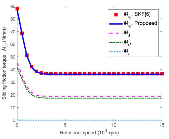
Table 4Numerical results of sliding friction torque and components under combined axial and radial loads, Fz = Fx = 1,000 N, DGBB 6206
Table 4
|
Inner ring rotational speed (n) [rpm] |
Sliding friction torque (Msl) [Nmm] |
Percentage error [%] |
|
Proposed (P) |
SKF (S) |
P-SS×100
|
|
500 |
67.6801 |
68.4875 |
1.1790 |
|
5,000 |
36.1996 |
36.6315 |
1.1790 |
|
15,000 |
36.1996 |
36.6312 |
1.1794 |
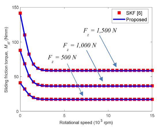
Fig. 16 shows the results of sliding friction torque estimation for a radial load of
Fx = 1,000 N, with varying axial loads of
Fz= 500, 1,000, and 1,500 N. In the comparison of the combined load case with the pure axial load case shown in
Fig. 10, the radial load does not change the sliding friction torque that much. This implies that the sliding friction torque is more sensitive to axial load than radial load.
Fig. 16Sliding friction torque under different combined loads; radial load Fx = 1,000 N, DGBB 6206

4. Conclusions
In this paper, an improved method was proposed that can efficiently estimate the sliding friction torque of DGBBs. The proposed method was validated by comparison with different models and that from a bearing manufacturer under several loading conditions for a range of rotational speeds. Through the simulations and analysis, the following conclusions were drawn:
1) The proposed method can accurately estimate the sliding friction torque including spinning and differential sliding friction torques for general conditions of loading and rotational speed.
2) The updated c-value is very useful to estimate sliding friction force.
3) The proposed method using the updated c-value is more accurate than any other method including the conventional method with a constant Coulomb friction coefficient.
4) Ball centrifugal force does not affect much the sliding friction torque in DGBBs.
5) Axial load contributes to the sliding friction torque more significantly than radial load in DGBBs.
6) For a pure radial loading case, only differential sliding friction torques exist while spinning friction torque vanishes.
7) For DGBBs, sliding friction torque is more sensitive to axial load than radial load.
In addition, it is worth mentioning that the proposed sliding friction torque model can be applied to ACBBs because no constraint is given for the initial contact angles of bearings.
ACKNOWLEDGMENTS
This research is supported by Kumoh National Institute of Technology in 2021.
REFERENCES
- 1.
Jin, C., Wu, B., Hu, Y., (2012), Heat generation modeling of ball bearing based on internal load distribution, Tribology International, 45(1), 8-15.
10.1016/j.triboint.2011.08.019
- 2.
Kekula, J., Smolík, J., Sulitka, M., (2017), Passive torque simulation of small angular contact bearing at high speed, MM Science Journal, 1-7.
http://hdl.handle.net/10467/87403
- 3.
Fernandes, C. M., Amaro, P. M., Martins, R. C., Seabra, J. H., (2013), Torque loss in thrust ball bearings lubricated with wind turbine gear oils at constant temperature, Tribology International, 66, 194-202.
10.1016/j.triboint.2013.05.002
- 4.
Tian, S., Chen, X., Chen, T., He, Y., (2019), Experimental analysis and modeling of the effects of oil-air lubrication parameters on bearings friction loss of high-speed motorized spindle, Tribology Transactions, 62(3), 524-534.
10.1080/10402004.2019.1584344
- 5.
- 6.
- 7.
- 8.
Stammler, M., Schwack, F., Bader, N., Reuter, A., Poll, G., (2018), Friction torque of wind-turbine pitch bearings-comparison of experimental results with available models, Wind Energy Science, 3(1), 97-105.
10.5194/wes-3-97-2018
- 9.
Kakuta, K., (1961), Friction moment of radial ball bearing under thrust load, Proceedings of the Japan Society of Mechanical Engineers, 27, 945.
10.1299/kikai1938.27.945
- 10.
Kanatsu, M., Ohta, H., (2008), Running torque of ball bearings with polymer lubricant (Running torque formulas of deep groove ball bearings under axial loads), Journal of Tribology, 130(4), 041507.
10.1115/1.2959119
- 11.
Wang, Y., Lin, F., Jiang, H., Yuan, W., (2015), Investigation on frictional characteristic of deep-groove ball bearings subjected to radial loads, Advances in Mechanical Engineering, 7(7).
10.1177/1687814015586111
- 12.
Tong, V.-C., Hong, S.-W., (2018), Improved formulation for running torque in angular contact ball bearings, International Journal of Precision Engineering and Manufacturing, 19(1), 47-56.
10.1007/s12541-018-0006-2
- 13.
Tong, V.-C., Hong, S.-W., (2018), Study on the running torque of angular contact ball bearings subjected to angular misalignment, Proceedings of the Institution of Mechanical Engineers, 232(7), 890-909.
10.1177/1350650117732921
- 14.
Houpert, L., (1999), Tribology: Numerical and analytical calculations in ball bearings, 8th European Space Mechanisms and Tribology Symposium, 283-290.
- 15.
Popescu, A., Houpert, L., Olaru, D., (2020), Four approaches for calculating power losses in an angular contact ball bearing, Mechanism and Machine Theory, 144, 103669.
10.1016/j.mechmachtheory.2019.103669
- 16.
Rivera, G. C., Tong, V. C., Hong, S. W., A study on ball-race contact in angular contact ball bearing during rotation, Journal of the Korean Society for Precision Engineering, 38(11), 851-862.
10.7736/JKSPE.021.086
- 17.
Tong, V.-C., Bae, G.-H., Hong, S.-W., (2015), Dynamic analysis of spindle supported by multiple bearings of different types, Journal of the Korean Society for Precision Engineering, 32(2), 117-125.
10.7736/KSPE.2015.32.2.117
- 18.
De Mul, J., Vree, J., Maas, D., (1989), Equilibrium and associated load distribution in ball and roller bearings loaded in five degrees of freedom while neglecting friction-Part II: Application to roller bearings and experimental verification, Journal of Tribology, 111(1), 149-155.
10.1115/1.3261865
- 19.
Hong, S.-W., Tong, V.-C., (2016), Rolling-element bearing modeling: A review, International Journal of Precision Engineering and Manufacturing, 17(12), 1729-1749.
10.1007/s12541-016-0200-z
- 20.
Harris, T. A., Kotzalas, M. N., (2006), Rolling Bearing Analysis-2 Volume Set, CRC Press.
10.1201/9781482275148
- 21.
Townsend, D., Allen, C., Zaretsky, E., (1974), Study of ball bearing torque under elastohydrodynamic lubrication, Journal of Tribology, 96(4), 561-570.
10.1115/1.3452491
- 22.
Aramaki, H., Shoda, Y., Morishita, Y., Sawamoto, T., (1988), The performance of ball bearings with silicon nitride ceramic balls in high speed spindles for machine tools, Journal of Tribology, 110(4), 693-698.
10.1115/1.3261715
- 23.
Jones, A., (1959), Ball motion and sliding friction in ball bearings, Journal of Basic Engineering, 81(1), 1-12.
10.1115/1.4008346
- 24.
Stolarski, T., (1990), Tribology in machine design, Industrial Press Inc.
Biography
- Gilbert Rivera
Received his M.S. degree in Mechanical Engineering and B.S degree in Mechanical System Engineering from Kumoh National Institute of Technology (KIT), Korea in 2017 and 2021, respectively, and his B.S. degree in Mechanical Engineering from Mapúa University, the Philippines in 2019. He is currently a Postmaster researcher at KIT, Korea.
- Van-Canh Tong
Received his M.S. degree in Mechanical Engineering from Hanoi University of Science and Technology, Vietnam in 2011. He earned his Ph.D. degree in Mechatronics from Kumoh National Institute of Technology, Korea in 2017. He is currently working at Samsung Display Vietnam.
- Seong-Wook Hong
Received his M.S. and Ph.D. degrees in Mechanical Engineering from KAIST, Korea, in 1985 and 1989, respectively. Currently, he is a Professor in the Department of Mechanical System Engineering of Kumoh National Institute of Technology. His current research interests include spindle and bearings modeling and analysis, command shaping for positioning systems, vibration control, and structural vibration analysis for mechanical systems.