ABSTRACT
The automotive electronic control unit outputs control signals using electrical signals of various input sensors installed in the vehicle to control the state of the engine, automatic transmission, and electric power steering (EPS). These units are installed inside the vehicle or engine room, and the temperature rises and falls by several tens of degrees due to the heat of the engine and the self-heating of the electronic control unit. Therefore, it was exposed to a thermal fatigue environment due to the difference in the coefficient of thermal expansion between the components, which caused frequent component damage. Solder cracks due to thermal fatigue in electronic control units are a key failure mode. However, because of its great heat capacity, the electronic control unit for automobiles took a long time to attain the desired temperature of high or low, and as a result, the 1,000-cycle test for thermal fatigue life verification required 3,167 hours (or 4.4 months). Therefore, in this study, the thermal shock cycle test time for the verification of the thermal fatigue life of electronic control units for automobiles was reduced by dividing it into two types.
-
KEYWORDS: Electronic control unit, Thermal fatigue, Accelerated life test method, Thermal shock cycle test, Rapid temperature change
-
KEYWORDS: 전자제어장치, 열 피로, 가속수명시험법, 열 충격 사이클 시험, 급속온도변화
1. 서론
자동차 전자제어장치(Electronic Control Unit, ECU)는 차량에 설치된 입력 센서의 전기적 신호를 이용한 제어 신호를 출력하여 엔진, 자동변속기, EPS (Electric Power Steering) 등의 상태를 제어하는 역할을 수행한다[
1]. 이러한 장치는 차량 실내 또는 엔진 룸에 장착되며, 태양열 및 차량 구동 시 엔진의 발열 그리고 전자제어장치 자체 발열로 수십 도의 온도상승과 하강이 발생한다[
2]. 그러므로 구성 부품 간 열팽창 계수 차이에 기인한 열 피로(Thermal Fatigue) 환경에 노출되며, 이로 인한 부품 손상이 빈번하게 발생하고 있다. 전자제어장치에 있어서 열 피로에 의한 솔더부(Solder) 크랙은 핵심 고장 모드이며, 열 충격 사이클 시험은 고온과 저온의 온도 차, 유지 시간(Dwell Time), 사이클 수와 같은 인자를 통해 가혹도를 조절할 수 있는 효과적인 검증방법이다[
3-
5]. 하지만 자동차용 전자제어장치는 큰 열용량으로 인해 고온 또는 저온의 목표 온도에 도달하는 시간이 긴 특징을 갖으며, 이로 인해 열 피로 수명 검증 1,000 사이클 시험을 위해 3,167시간(약 4.4개월)이 소요된다[
6].
한편 국내외 자동차 제조업체들은 리콜과 클레임으로 인한 품질, 신뢰성 및 안전성 강화의 일환으로 제품 수명에 대한 개발목표 및 보증기간을 확대하는 추세이다. 이러한 상황에서 차량의 개발기간은 지속적으로 단축되고 있어, 단계별로 이루어지는 개발 평가 및 양산 평가 등 신뢰성 검증에 필요한 기간을 확보하는 것도 쉽지 않다. 따라서 신뢰성이 검증되지 못한 제품의 양산은 고객의 클레임 및 리콜 그리고 브랜드 이미지 하락 등으로 이어져 막대한 경제적 손실을 초래할 수 있다. 그러므로 단축된 차량 개발 기간에 대응하면서, 클레임 방지를 위한 설계 검증 및 고신뢰성의 입증을 위해서는 신뢰성 검증 기간의 단축이 절실히 요구되고 있다.
따라서 본 연구에서는 자동차용 전자제어장치의 열 피로 수명 검증을 위한 열 충격 사이클 시험시간을 두 단계로 나누어 단축하고자 한다. 즉, 1단계에서는 이론적 모델 검증을 통한 가속시험모드를 도출하는 것으로써, 기존 정규모드와의 열 피로 가혹도가 동등하다는 것을 확인하여 가속수명시험법의 타당성을 검증하고자 한다. 그리고 2단계에서는 정상 조건 시험 중 개발 제품에 크랙이나 파손과 같이 고장이 발생한 경우 검증 시간을 획기적으로 단축하기 위한 방안을 제안하고자 한다.
2. 고장 분석 및 가속수명시험 모델 이론
2.1 전자제어장치의 고장 분석
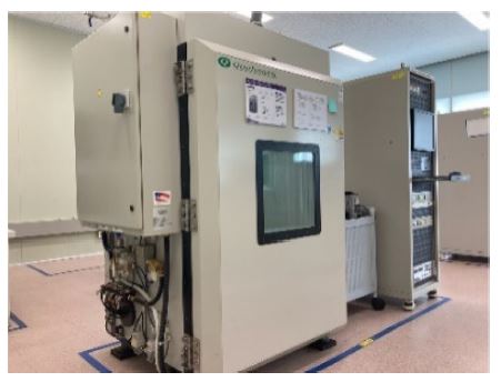
본 연구의 대상 제품은
Fig. 1과 같이 자동차용 전자제어장치이다. 이러한 장치는 열팽창 계수가 다른 다양한 부품으로 구성되며 이로 인해 이종 소재 간 반복적인 온도변화 발생 시 열팽창 계수의 차이로 팽창과 수축과정에서 구성 부품 간 열 피로를 야기한다. 이때, 이종 소재 간 접촉에 의한 열 피로에 의해 문제가 되는 주요 고장 부위는
Fig. 2에 나타낸 것처럼 PCB 내 회로를 형성하는 동박부 및 솔더부 크랙이다. 최근 전기전자제품 유해물질 사용제한 지침(RoHS)의 강화로 기존의 유연 솔더 대신 무연 솔더(Lead-Free Solder)로 대체함으로써 신뢰성 검증이 중요한 이슈로 대두되고 있다[
4].
Fig. 1Electronic control unit
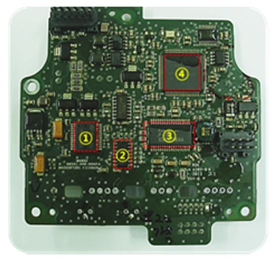
Fig. 2Main failure mode of electronic control unit
2.2 가속수명시험 모델 이론
탄성 상태(Elastic State) 재료의 피로 수명은
식(1)에 나타낸 것처럼 변형률 변화에 대한 반비례 관계로 정의할 수 있다[
7,
8].
여기서,
Ncycle은 반복적인 온도변화에 의한 솔더부 파단 또는 크랙 수명이며, Δ
ε, m 및 C
1은 팽창 및 수축에 따른 변형량 변화, Coffin-Manson 지수와 재료 상수를 각각 의미한다. 이때, 탄성 상태 다종 재료의 열 변형량은 온도변화에 비례하며, 큰 소성변형 및 크리프(Creep) 상태에서도 열 변형량은 온도 프로파일에 따른다. 따라서
식(1)의 팽창 및 수축에 따른 변형량은
식(2)와 같이 온도변화량으로 치환할 수 있다[
7,
8].
여기서, Δ
T는 반복적인 온도변화를 의미한다.
식(2)의 양변에 로그를 적용하고 정리하면
식(3)과 같다.
따라서
식(3)을 여러 가지 재료에 대하여 온도 차이와 피로 수명과의 관계를 그래프로 나타내면
Fig. 3과 같다.
Fig. 3Life for each material according to temperature difference
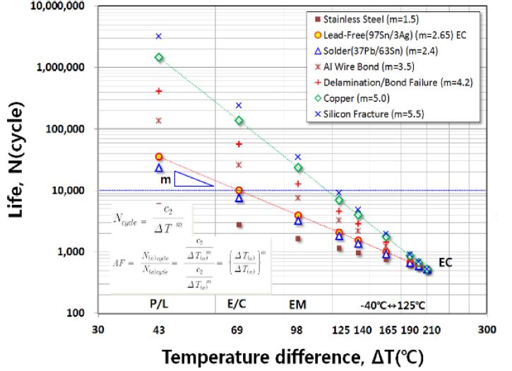
즉, 온도변화에 따른 수명의 기울기를 나타내는 Coffin-Manson 지수는 Cu(5.0), Silicon(5.5)과 같이 전자제어장치의 PCB를 구성하는 주요 재료에 대한 값이 스테인리스 강(1.5) 소재를 제외하면 무연 솔더(2.65) 또는 유연 솔더(2.4) 보다 큰 것을 확인할 수 있다. 따라서 전자제어장치를 구성하는 많은 부품 중 열 피로에 취약한 부위는 솔더부이며, 따라서 본 연구에서는 무연 솔더를 대상으로 열 피로를 고려한 가속수명시험법을 개발하고자 한다.
한편,
식(2)로부터 정상 조건의 피로 수명에 대한 가속 조건에 대한 수명의 비를 나타내는 가속 계수(Acceleration Factor)는
식(4)와 같다.
여기서, 첨자 n과 a는 정상 조건과 가속 조건을 각각 의미한다.
3. 전자제어장치의 가속수명시험
3.1 기초 실험
2.2절에서 언급한 것처럼 탄성과 큰 소성변형 상태에서의 열 변형률 변화는 온도 프로파일을 따른다고 하였다. 즉, 팽창 및 수축에 의한 변형률의 변화(Δε)는 온도변화량(ΔT)과 정비례 관계이어야 한다. 이의 실험적 검증을 위하여
Fig. 4와 같은 장치를 통해 PCB와 주요 부품의 온도변화량에 따른 열 변형률 변화를 측정하고자 하며, 실험을 위한 변형율 게이지(Strain Gauge)는 열팽창 계수가 거의 제로에 가까운 소재인 Titanium Silicate (Δε = 0.02 × 10
-6/°C)를 사용하였다.
Fig. 4Thermal expansion measurement equipment for PCB and parts (Half-bridge)
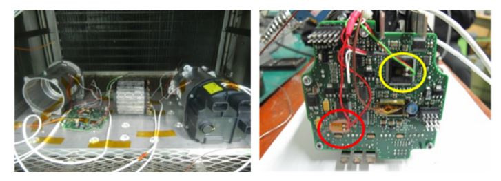
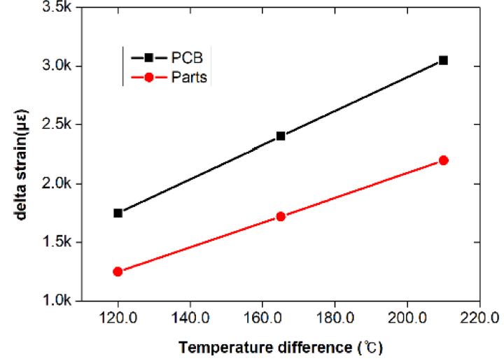
Fig. 5는 3가지 온도 차이를 갖는 열 충격 사이클에 의한 전자제어장치용 PCB와 주요 부품의 변형률의 변화량을 나타낸 것이며, 이를 통해 변형률 변화는 온도 차가 증가함에 따라 거의 선형적으로 증가하는 것을 알 수 있다. 따라서 2.2절에서 언급한
식(1)과
식(2)의 관계가 유효함을 실험을 통해 확인하였다.
Fig. 5Strain comparison between PCB and parts according to the temperature differences

3.2 열 충격 사이클 시험 인자 선정
열 충격 사이클 시험은 고온과 저온의 온도 차, 유지 시간, 사이클 수와 같은 인자를 통해 열 피로 가혹도를 조절할 수 있는 효과적인 방법이다[
3].
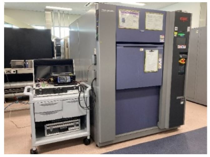
Fig. 6에 나타낸 열 충격 시험기를 이용한 예비시험을 통해 본 연구의 대상 제품인 전자제어장치에 대한 동작한계 상한과 하한을 확인하였으며, 이를 통해 가속 조건의 최대 온도 차이를 210°C(-60↔150)로 설정하였다. 그리고 2.2절에서 언급한 것처럼 무연 솔더에 대한 Coffin-Mansion 지수는 2.65를 적용하였다. 따라서, 정상 조건의 온도 차이 165°C(-40↔125)와 가속 조건을
식(4)에 적용하면 AF (Acceleration Factor)는 약 1.895가 얻어지며, 이를 통해 정상 조건과 가속 조건의 사이클 수는 각각 1,000과 528이 얻어진다.
Fig. 6Test equipment of thermal shock cycle

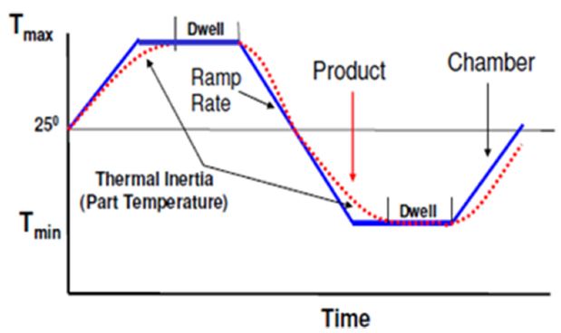
한편, 일부 부품의 경우 큰 열용량으로 인해 고온 또는 저온의 목표 온도에 도달하는 시간이 긴 특징을 갖는다. 그러므로 가속시험을 통해 도달하고자 하는 목표 온도를 변경(고온의 경우 기준값 보다 높게 설정하며, 저온의 경우 기준값 보다 낮게 설정)하는 경우 대상 부품의 온도가 원하는 목표 온도에 도달했는지 확인하는 것이 필요하며, 이를 위하여 유지 시간에 대한 실험적 검증이 필요하다.
Fig. 7은 대상 부품의 열용량 및 유지 시간에 따른 온도변화를 나타낸 것이며, 부품의 온도는 열용량에 따라 서서히 챔버의 온도에 도달하게 되며 대상 부품에 대한 여러 번 시험을 통해 유지 시간 인자는 10분으로 설정하였다.
Fig. 7Dwell time considering thermal inertia

3.3 가속수명시험 실시 및 검증
Table 1은 정상 조건과 2.2절의 이론 및 유지 시간을 고려한 실험을 통해 도출한 가속 조건의 시험 모드이다. 즉, 기존 정상 조건의 경우 165°C(-40↔125) 온도 차이를 적용한 1,000 사이클(약 4.4개월)이며, 가속 조건은 210°C(-60↔150)의 온도 차이와 각각에 대한 사이클 타임(Cycle Time)의 효율적인 설정을 통해 528 사이클(약 2.2개월)로 시험시간을 약 50.0% 단축한 것을 의미한다.
Table 1Normal and acceleration experiment mode for thermal shock cycle test
Table 1
|
Experiment mode |
Low temp. [°C] |
High temp. [°C] |
Cycles |
Total time [hours] |
|
Normal |
-40 |
125 |
1,000 |
3,167 |
|
Acceleration |
-60 |
150 |
528 |
1,593 |
상기의 가속시험모드에 대한 적용 가능성 평가를 위해서는 정상 및 가속 조건에 대한 한계 시험을 수행하고 각각의 시험 조건에서 발생한 솔더부 크랙에 대한 저항 측정을 통해 동일한 고장이 발생한 것을 확인하는 것이 필요하다. 하지만, 전자제어 장치 내 다양한 부품이 장착된 상태에서는 기존에 구성된 각종 회로의 영향에 의해 관심 부위만의 저항 측정이 불가능하다. 따라서, 본 연구에서는 시험시간 단축을 위해 제시한 가속시험모드의 타당성 평가를 위해 열 충격 사이클 시험 전과 후 열 피로에 의한 솔더부 접합 하중을 측정하여 상호 비교하는 방법을 제안하고자 한다[
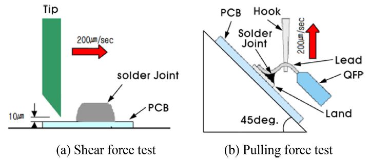
4]. 즉,
Fig. 8에 나타낸 것처럼 전자제어장치에 장착된 부품의 형태에 따라 RLC 표준칩의 경우 전단력(Shear Force)을 측정하며[
9], IC (Integrated Circuit) 또는 QFP (Quad Flat Package) 형태의 칩에 대해서는 45
o 리드에 대한 당기는 힘(Pulling Force)을 측정 한다[
10].
Fig. 9는 정상 및 가속 조건에 대한 열 충격 사이클 시험 전과 후 솔더부 전단력과 당기는 힘을 비교하여 나타낸 산점도이다. 이때, 대표적인 측정 부품의 위치와 시험 장치는
Fig. 10과 같다.
Fig. 8Solder joint force measurement method

Fig. 9Comparison of solder joint shear and pulling force for different chips in thermal shock cycle test
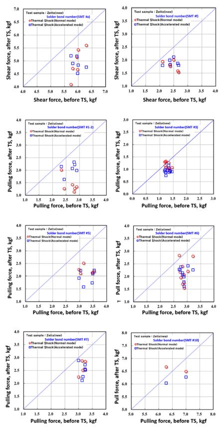
Fig. 10Solder joint force measurement parts and equipment
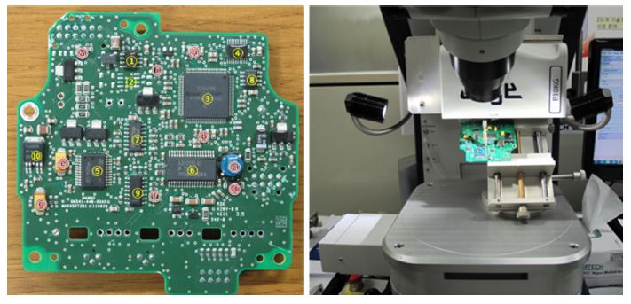
즉, 산점도의 가로축 값은 열 충격 사이클 시험 전 전자제어장치 부품에 대하여 측정된 하중(전단력 또는 당기는 힘)을 나타내며, 세로축 값은 열 충격 사이클 시험 후 측정된 하중을 각각 의미한다. 따라서 표시된 데이터가 대각선에 위치하면 열 충격 사이클에 의한 열화가 진행되지 않았다는 것이며, 대각선 아래에 위치하면 열화가 된 것이다. 그러므로
Fig. 9에 나타낸 것처럼 정상 및 가속 조건에서 대부분 대각선 아래에 산점도가 표시되는 것을 확인할 수 있으며, 흩어진 정도인 산포도 유사한 것을 알 수 있다.
한편, 솔더부 접합 하중의 변화에 대한 통계적인 분석을 위해 서로 다른 두 조건에서 측정된 값의 실험 전과 후 측정값의 차이 분석에 유용한 쌍체 t-검정(Paired t)을 실시하였다. 이때 사용된 귀무가설은 ‘정상과 가속시험모드 변화에 따른 솔더부 접합 하중의 차이는 없다.’이며, 미니탭(Minitab)의 쌍체 t-검정 실시를 위한 입력 조건인 대립가설은 ‘정상과 가속시험모드에 따른 솔더부 접합 하중은 같지 않다.’이다. 이때, 일반적으로 새로운 시험방법을 채택하거나 유의성 검증을 위하여 보수적인 접근이 필요하므로 신뢰수준 95%의 확신으로 동등성을 검증하고자 한다. 따라서 유의수준(α)은 5%, 즉 0.05로 선정하였으며, 신뢰수준은 95%이다. 그러므로 유의수준(α)과 쌍체 t-검정의 결과인 P-value를 비교하여, P-value 값이 유의수준보다 작으면 귀무가설을 기각한다.
Table 2는 정상과 가속시험모드의 열 충격 사이클 시험 후 솔더부 접합 하중에 대한 쌍체 t-검정 결과를 나타낸 것이다. 즉, 당기는 힘의 경우 총 7개의 부품 중 5개 부품의 P-value가 유의수준 0.05보다 큰 값이 도출되었으며, 전단력의 경우 3개 부품 모두 유의수준 보다 큰 값이 얻어져 정상과 가속시험모드 변화에 따른 솔더부 접합 하중의 차이가 없다고 할 수 있다. 하지만, 부품 1-2번과 3번의 경우 P-value가 유의수준보다 작은 값이 도출되어 통계적으로 차이가 있음을 알 수 있다. 즉, 부품 1-2는 정상 시험 모드가 부품 3의 경우 가속 시험 모드가 각각 가혹한 결과를 보인다. 이러한 차이의 발생 원인은 솔더 접합부 SMT (Surface Mounter Technology) 공정에서 다양한 기공(Void)이 형성되며, 열 충격 사이클 시험 후 발생하는 여러 형태의 미세균열로 인한 제품의 편차 때문으로 추정된다.
Table 2Paired t-test analysis result between normal and accelerated experiment mode
Table 2
|
Part number (Test points) |
Experiment mode |
Force μ |
Force σ |
P-value |
#1-2
(6/Pulling) |
Normal |
1.4 |
0.31 |
0.008 |
|
Acceleration |
2.06 |
0.24 |
#3
(12/Pulling) |
Normal |
1.12 |
0.14 |
0.006 |
|
Acceleration |
0.94 |
0.10 |
#5
(6/Pulling) |
Normal |
2.22 |
0.15 |
0.165 |
|
Acceleration |
1.96 |
0.27 |
#6
(10/Pulling) |
Normal |
2.14 |
0.44 |
0.831 |
|
Acceleration |
2.12 |
0.26 |
#7
(6/Pulling) |
Normal |
2.59 |
0.24 |
0.684 |
|
Acceleration |
2.51 |
0.29 |
#9
(6/Pulling) |
Normal |
2.57 |
0.3 |
0.18 |
|
Acceleration |
2.43 |
0.12 |
#10
(2/Pulling) |
Normal |
6.58 |
0.13 |
0.289 |
|
Acceleration |
6.15 |
0.17 |
#a
(6/Shear) |
Normal |
4.94 |
0.56 |
0.892 |
|
Acceleration |
4.90 |
0.26 |
#b
(6/Shear) |
Normal |
1.79 |
0.18 |
0.212 |
|
Acceleration |
1.92 |
0.13 |
#f
(6/Shear) |
Normal |
1.77 |
0.19 |
0.108 |
|
Acceleration |
1.90 |
0.13 |
따라서 상기의 산점도와 쌍체 t-검정을 통해 제안한 가속시험 모드의 적용 가능성을 확인하였으며, 이러한 검증 방법은 정상 조건 열 충격 사이클 시험에서 크랙이나 파손과 같이 고장이 발생하지 않은 경우에 적용할 수 있는 시험법이다.
4. 급속온도변화를 이용한 가속시험법
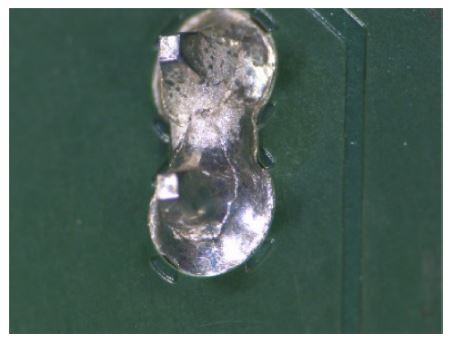
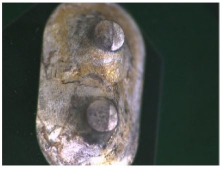
3장에서 도출한 1단계 가속시험모드는 전자제어장치에 대한 정상 조건 열 충격 사이클 시험 1,000사이클과 유사한 열화(전단력 또는 당기는 힘 감소)를 갖도록 하면서 시험시간을 약 50.0% 수준으로 단축하기 위한 가속시험법을 제시한 것이다. 하지만, 개발 중인 제품에 대한 열 충격 사이클 시험 과정 중 크랙이나 파손이 발생한 경우 시간상의 문제로 상기의 방법을 적용하기 어려우며, 이의 개선을 위해서는 설계변경과 함께 빠른 검증을 위하여 유사한 고장을 유발하면서 시험시간을 획기적으로 단축하기 위한 방안이 필요하다. 즉, 정상 조건 열 충격 사이클 시험 과정 중 개발 제품에
Fig. 11과 같은 원형 크랙이 발생한 경우 반드시 설계변경이 필요하며, 평가를 위해 1단계 가속시험모드를 적용하면 최소 2개월이 소요된다. 따라서, 본 연구에서는 문제가 발생한 제품의 신뢰성 검증 시간을 획기적으로 단축하기 위하여 급속온도변화를 이용한 가속시험법의 적용 가능성을 검토하고자 한다.
Fig. 11 Circular crack generated by normal mode thermal shock cycle test
4.1 급속온도변화 시험 장치
정상 조건 열 충격 사이클 시험의 경우
Fig. 6에 나타낸 ESPEC 사의 TSA-203EL 모델(보증 온도 -65-200°C)을 이용하여 챔버(Chamber) 내부 공기를 냉각 또는 가열하는 에어 투 에어(Air to Air) 방식을 적용하므로 저온 또는 고온의 목표 온도에 도달하기 위하여 비교적 긴 시간이 소요되는 장치이다. 한편,
Fig. 12에 나타낸 Qualmark 사의 Typhoond-2.5+ 모델(보증 온도 -100-200°C)은 초가속수명시험(Highly Accelerated Life Test)에 적용할 수 있는 장치로써 냉각의 경우 액체질소를 기화시켜 분무하며, 가열의 경우 목표 온도로 가열된 공기를 대상 제품에 직접분사하는 방식을 적용하므로 짧은 시간에 저온 또는 고온의 목표 온도에 도달하도록 하여 급속온도변화(Rapid emperature Change, RTC) 시험이 가능한 장치이다.
Fig. 12Test equipment for rapid temperature change

4.2 급속온도변화 시험 및 고찰
Table 3은 대상 제품에 대한 열 충격 사이클 시험의 정상 조건과 급속온도변화 조건의 시험 모드이다. 즉, 기존 정상 조건의 경우 165°C 온도 차이를 적용한 1,000 사이클(약 87일)이며, 급속온도변화 조건은 240°C의 온도 차이와 각각에 대한 사이클 타임의 효율적인 설정을 통해 370 사이클(약 6일)로 시험시간을 약 93.0% 단축한 것을 의미한다.
Table 3Normal and rapid temperature change experiment mode for thermal shock cycle test
Table 3
|
Experiment mode |
Low temp. [°C] |
High temp. [°C] |
Cycles |
Total time [days] |
|
Normal |
-40 |
125 |
1000 |
87 |
|
RTC |
-90 |
150 |
370 |
6 |
상기의 시험에 대한 타당성 평가를 위해서는 정상 및 급속온도변화 조건의 열 충격 사이클 시험을 수행하고 각각의 시험 조건에서 발생한 솔더부 크랙에 동일한 고장이 발생한 것을 확인하는 것이 필요하다. 즉,
Figs. 11과
13은 정상 및 급속온도변화 조건에서 열 충격 사이클 시험 후 발생한 크랙을 비교한 것이며, 두 가지 조건에서 동일한 파손 형태(원형 크랙)가 나타난 것을 확인할 수 있다. 따라서 급속온도변화 시험의 경우 정상 조건 열 충격 사이클 시험에서 크랙이나 파손과 같이 고장이 발생한 경우에 적용할 수 있는 효과적인 시험시간 단축 방법이다.
Fig. 13Circular cracks caused by thermal shock cycle test with rapid temperature change
5. 결론
자동차 전자제어장치의 열 피로(Thermal Fatigue)에 의한 핵심 고장 모드 인 솔더부 크랙의 열 충격 사이클 시험을 위한 가속시험법을 개발하였으며, 이를 통해 다음과 같은 결론을 얻었다.
(1) 전자제어장치를 구성하는 PCB와 주요 부품의 열팽창계수 차이에 의해 솔더부 열 피로가 발생되며, 이의 효과적인 검증을 위하여 Coffin-Manson 모델을 이용한 열 충격 사이클 시험의 가속시험모드를 개발하였으며 이를 통해 약 50.0% 시험시간을 단축하였다.
(2) 개발된 가속시험모드를 적용한 시험 결과를 전자제어장치에 장착된 부품의 형태에 따라 전단력과 당기는 힘을 이용하여 열화(전단력 또는 당기는 힘 감소) 상태를 확인하고, 쌍체 t-검정을 통한 정량적 통계분석을 실시하여 정상조건과의 가혹도 동등성을 확인하였다.
(3) 급속온도변화를 이용한 열 충격 사이클 시험에서 정상 조건과 동일한 파손 형태(원형 크랙)가 얻어져 제품 설계 단계에서 발생한 고장 문제 발생 시 빠른 개선 검증이 가능할 것으로 사료된다.
REFERENCES
- 1.
- 2.
Kang, G. B., (2020), A law and policy study on tuning of automotive electronic control units (ECU), Hanyang Law Review, 31(3), 145-168.
10.35227/HYLR.2020.08.31.3.145
- 3.
Ha, S.-S., Kim, J.-W., Chae, J.-H., Moon, W.-C., Hong, T.-H., Yoo, C.-S., Moon, J.-H., Jung, S.-B., (2006), Thermo-mechanical reliability of lead-free surface mount assemblies for auto-mobile application, Journal of Welding and Joining, 24(6), 21-27.
- 4.
Jeon, Y.-J., Kim, D.-S., Shin, Y.-E., (2011), A study on the fracture mode characteristics of automotive application component lead-free solder joints, Transactions of the Korean Society of Automotive Engineers, 19(6), 90-96.
- 5.
Hampshire, W. B., (1993), The search for lead-free solders, Soldering & Surface Mount Technology, 5(2), 49-52.
10.1108/eb037826
- 6.
ES95400-10, (2019), Environmental test for automotive electronic devices.
- 7.
Coffin Jr, L. F., (1954), A study of the effects of cyclic thermal stresses on a ductile metal, Transactions of the American Society of Mechanical Engineers, 76(6), 931-949.
10.1115/1.4015020
- 8.
Manson, S. S., (1953), Behavior of materials under conditions of thermal stress, National Advisory Committee for Aeronautics.
- 9.
JIS Z 3198-7, (2003), Test methods for lead-free solders - Part 7: Methods for shear strength of solder joints on chip components, Japanese Standards Association (JSA).
- 10.
JIS Z 3198-6, (2003), Test methods for lead-free solders - Part 6: Methods for 45 degree pull test of solder joints on QFP lead, Japanese Standards Association (JSA).
Biography
- Tae Kyung Kim
He is working for the Electronics Reliability & Validation Team in Mando Co., Ltd. as a Senior researcher. His research interest is the reliability evaluation of electronics.
- Jung Hwan Lee
Associate Professor in the Department of Automotive Engineering, Osan University. His research interest is the reliability evaluation of electronics in vehicle.