ABSTRACT
Strain wave gears are widely used in applications that require high reduction ratios, compact designs, and high positioning accuracy. However, increasing torque capacity remains a key challenge, particularly due to the high stresses at the flex spline tooth root. This study presents the development and investigation of a new strain wave gear variant. The tooth profile is defined using a quadruple-arc geometry with tangential transitions. A two-dimensional tooth engagement analysis evaluates the meshing behavior under flex spline deflection and identifies potential collisions during the design phase. Consequently, an FE simulation was conducted to investigate stress distribution. In the final step, the developed strain wave gear was assessed for overall performance and load capacity. Performance evaluations, including hysteresis loss, showed that the developed strain wave gear performed equally well or better than a leading strain wave gear manufacturer across seven key performance metrics. In terms of load capacity, the maximum torque at 50% failure probability (T50%) reached 106.7 Nm, which is 30% higher than the development target of 82 Nm, thereby confirming the validity of the tooth-profile design.
-
KEYWORDS: Strain wave gear, Quadruple-arc profiles, Tooth engagement analysis, Performance and load capacity tests
-
KEYWORDS: 스트레인 웨이브 기어, 쿼드러플 아크 치형, 치합분석, 성능 및 하중 용량 평가
NOMENCLATURE
Head Radius Length Factor
Head Radius Runout Factor
1. Introduction
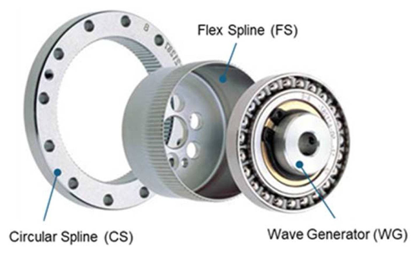
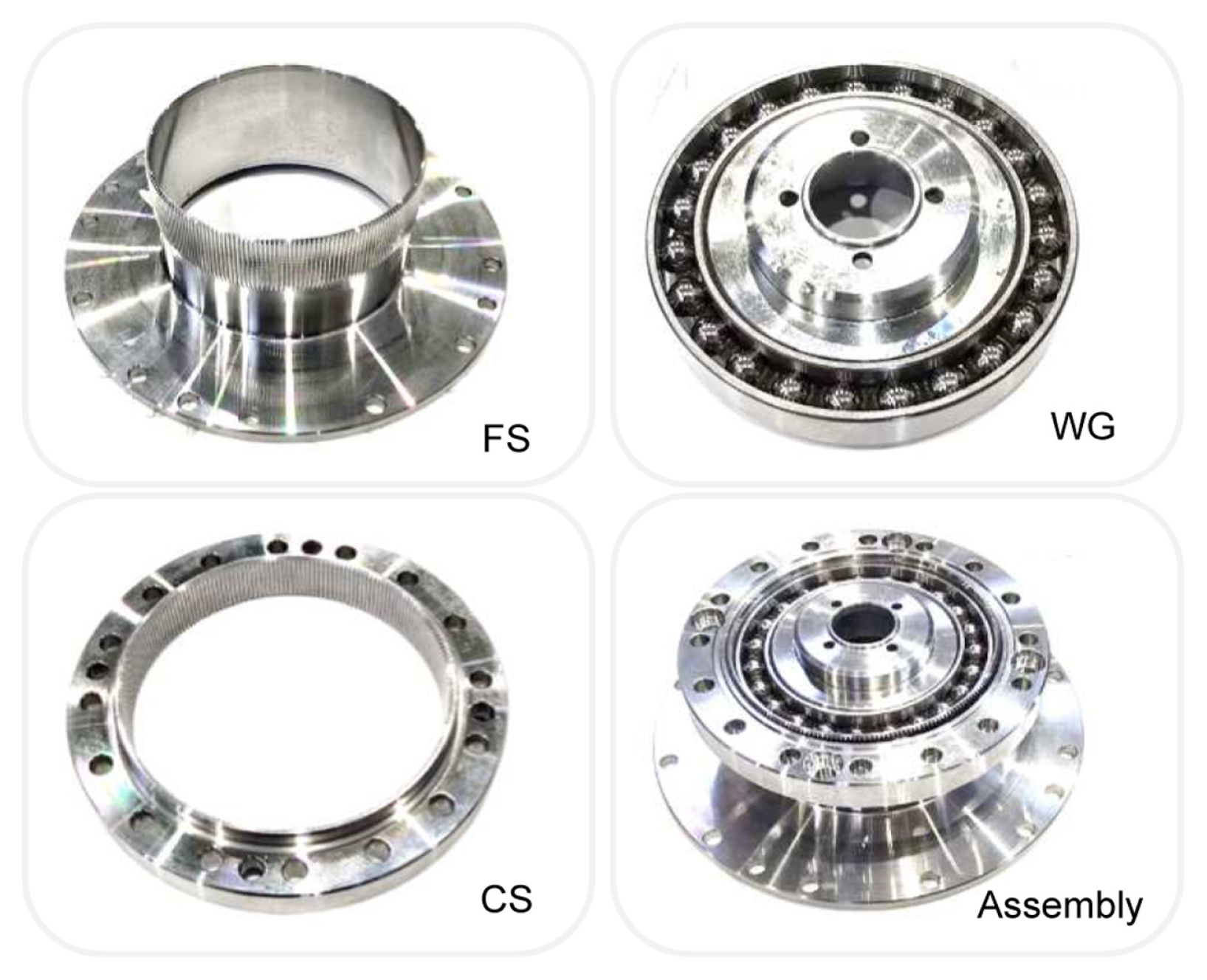
Strain wave gears, also known as harmonic drives, are widely used in high-precision applications such as aerospace and industrial robotics because of their compact size, high reduction ratios, and excellent positioning accuracy. These gears consist of three key components: the flex spline (FS), circular spline (CS), and wave generator (WG), as shown in
Fig. 1. To improve the tooth engagement area of strain wave gears, considerable research has been devoted to tooth-profile design. Ivanov [
1] and Zhang et al. [
2] investigated strain wave gear tooth profiles and their meshing process. Several studies have investigated double-arc and quadruple-arc tooth profiles [
3-
5]. In particular, Eloy Yague- Spaude [
5] investigated quadruple-arc tooth profiles, which provide greater geometric flexibility through independent control of the tooth-root and tooth-tip regions, thereby enabling more refined optimization of stress distribution, meshing quality, and load-carrying capacity. In addition, Zhiyuan Yu et al. [
6,
7] examined validation methods for strain wave gears using analytical approaches. Building on these previous studies, this paper presents the design, development, and validation of a strain wave gear for standard-torque applications. The developed gear was designed for a repeated peak torque of 82 Nm, with a reduction ratio of 100 : 1 and 20-inch size.
2. Tooth Profile Design
This section presents the geometric design and profile definition of the strain wave gear. The objective is to develop feasible and collision-free tooth geometries that serve as the basis for subsequent numerical and experimental investigations. The design of the flex spline and circular spline is described below.
2.1 General Gear Data
The strain wave gear set considered in this study has a module of m = 0.254, with z
1 = 200 teeth for the flex spline and z
2 = 202 teeth for the circular spline. The profiles of the circular spline and flex spline are defined using a quadruple-circular-arc geometry. Compared with the involute tooth profile, this profile type provides advantages such as a higher number of meshing tooth pairs and a more uniform stress distribution. Furthermore, compared with the double-arc profile, it includes a larger number of design variables, which increases the degree of freedom in tooth-profile design and enables more flexible optimization of tooth contact characteristics. For both the circular spline and the flex spline, the profile definition begins with the selection of two major radii, φ
a and φ
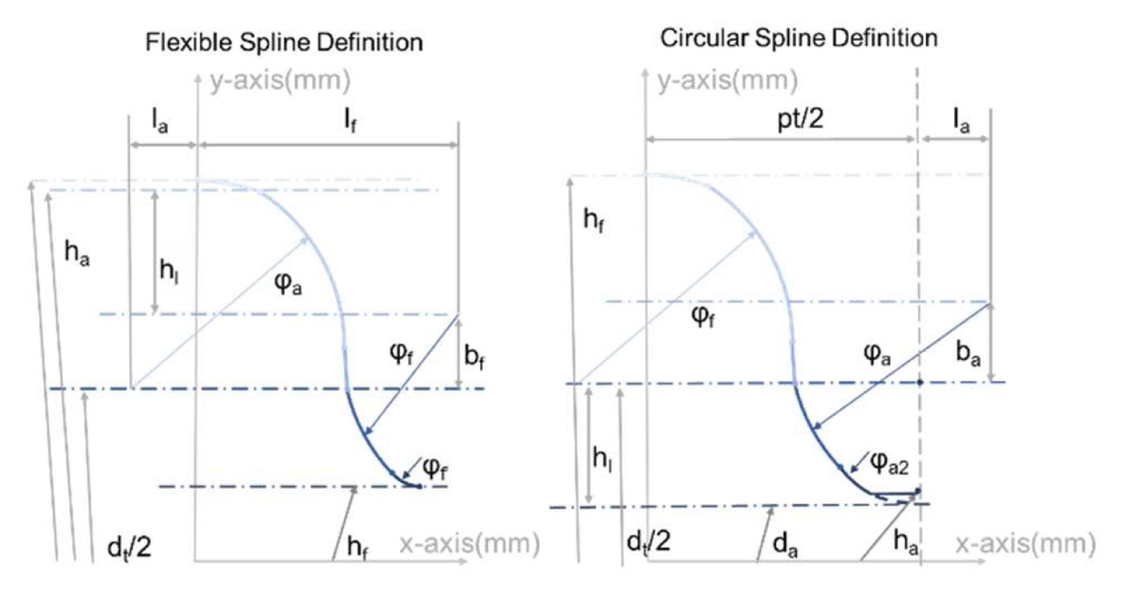
f, which are key design parameters governing the initial tooth contact. Additional arcs are then introduced at the tooth root of the flex spline and at the tooth tip of the circular spline to ensure smooth profile transitions. Tangential continuity is imposed between adjacent arcs. Further parameters are used to define the positions of the arc centers, and some of these parameters are therefore interdependent. The parameters used for the profile definition are shown in
Fig. 2.
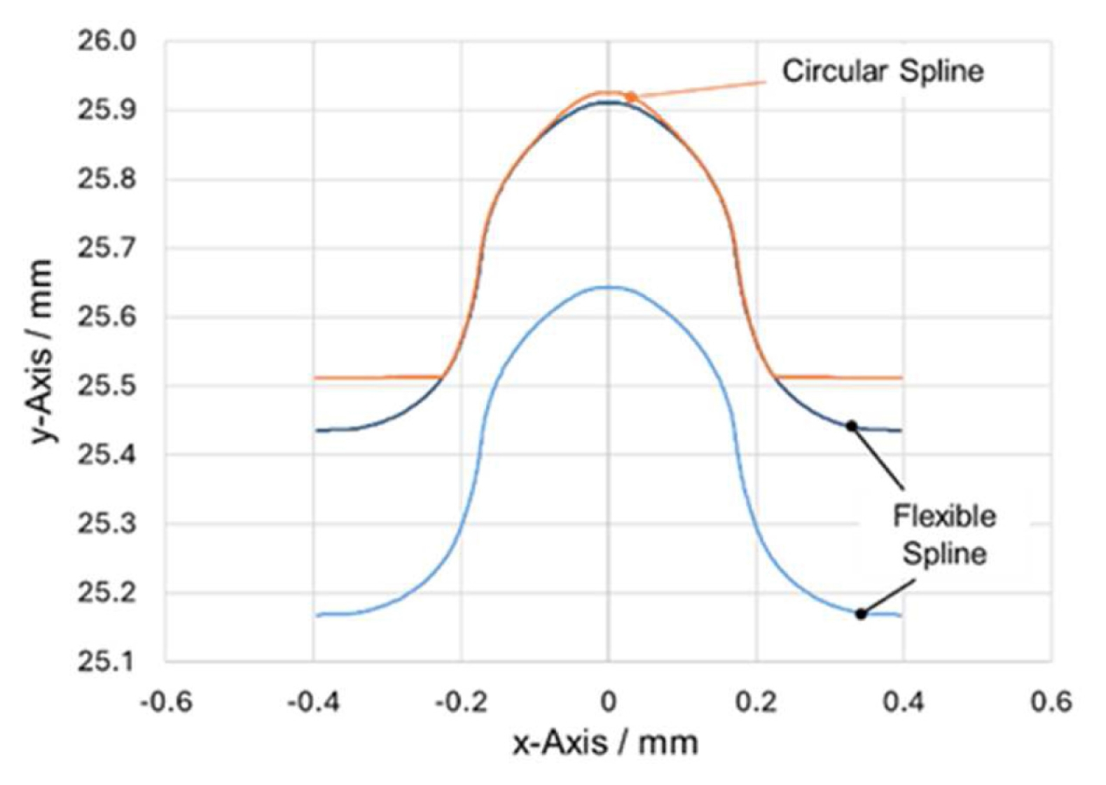
Based on the profile definitions introduced in Section 2.1, the profile parameters for the circular spline and flex spline were determined. The resulting quadruple-circular-arc tooth profiles are shown in
Fig. 3, while the corresponding geometric parameters are summarized in
Table 1. In addition, the wave generator deflection was selected as ω₀ = 0.27 mm based on the results of finite element and tooth engagement analyses. To evaluate the meshing condition between the two gears, the flex spline profile was considered in its deflected state. This placed the flex spline tooth at its maximum radial extension and enabled a preliminary analysis of the meshing between the two gears.
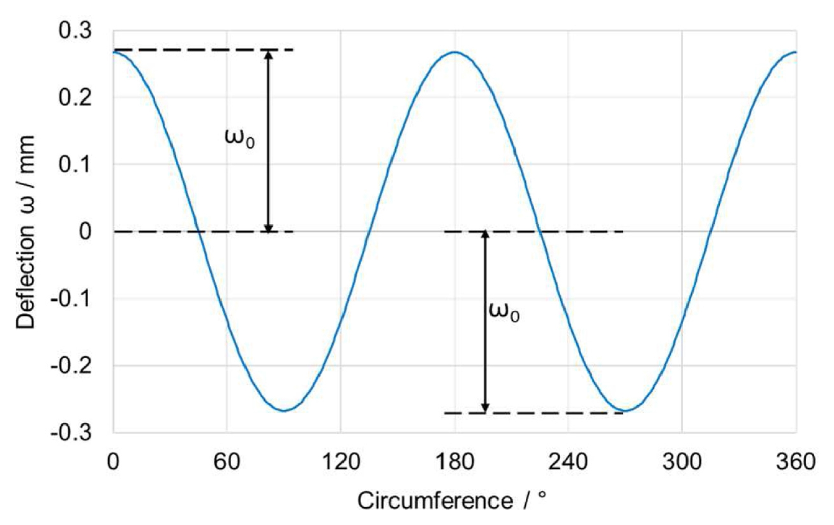
The wave generator shape considered in this study resembles that of a ring deformed by two opposing forces. The variation in the deflection along the circumference of the wave generator can be described mathematically by
Eq. (1).
The circumferential variation of the deflection ω for the two-force model is shown in
Fig. 4. The deflection follows a cosine function. The maximum positive deflection, ω
0 = 0.27 mm, occurs at 0° and 180°. Similarly, the maximum negative deflection of -0.27 mm occurs at 90° and 270°. Overall, the deflection distribution is symmetric, and the transition between positive and negative deflection is smooth.
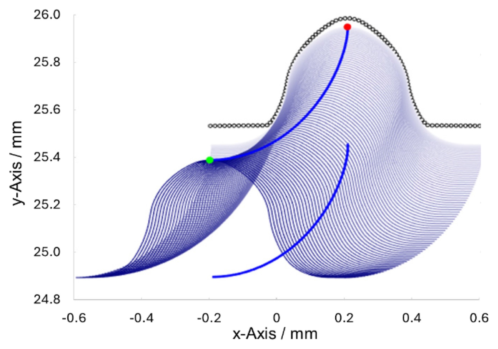
To analyze potential collisions between the flex spline and the circular spline during the design phase, a tooth engagement analysis was developed and implemented in MATLAB. This analysis serves as a purely geometric preliminary assessment. It enables the identification of potential collisions or penetrations during meshing, but it does not provide information on stress distribution or load capacity. For this purpose, the wave generator is rotated through 90°. Owing to symmetry, no further rotation is required. The resulting motion of the flex spline tooth relative to a fixed circular spline gap is visualized in
Fig. 5. In addition, the trajectories of the tooth tip and tooth root are shown as two blue curves. If a collision or penetration with the circular spline occurs at any point during the motion of the flex spline profile, the analysis generates a warning. This makes it possible to evaluate the meshing condition and adjust the profile parameters accordingly. Since no warning is generated for the selected parameters, they are considered suitable for subsequent FE simulations.
3. Finite Element Analysis and Validation
The designed tooth profiles of the flex spline and the circular spline are investigated using finite element (FE) simulation. In this analysis, the wave generator geometry is considered, and the stress distribution at the tooth root, the contact pressure distribution along the flank of the flex spline, the number of teeth in contact, and the continuity of tooth contact are evaluated.
3.1 Structural Analysis of the Tooth Profile
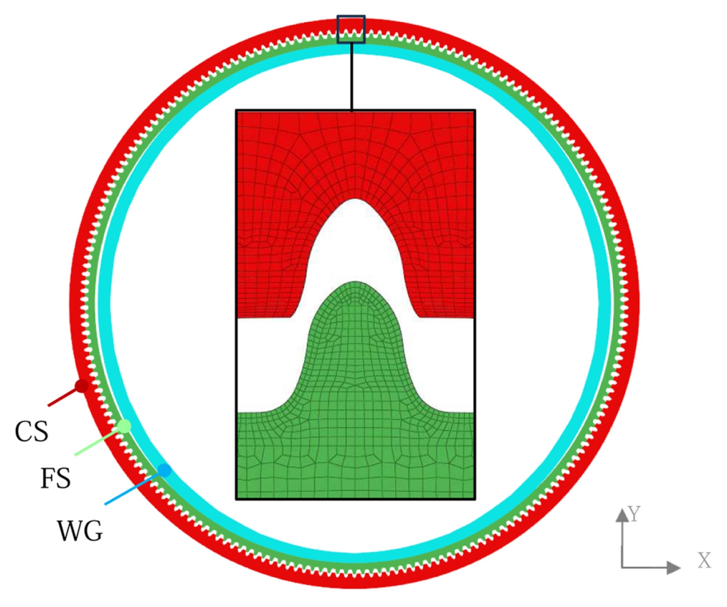
To investigate the tooth profile of the strain wave gear, a two-dimensional finite element model of the flex spline, circular spline, and wave generator in the standard configuration was developed (
Fig. 6). This model represents a 2.4 mm-wide central section of the tooth profile and was analyzed under plane-strain conditions. The material properties used in the analysis are summarized in
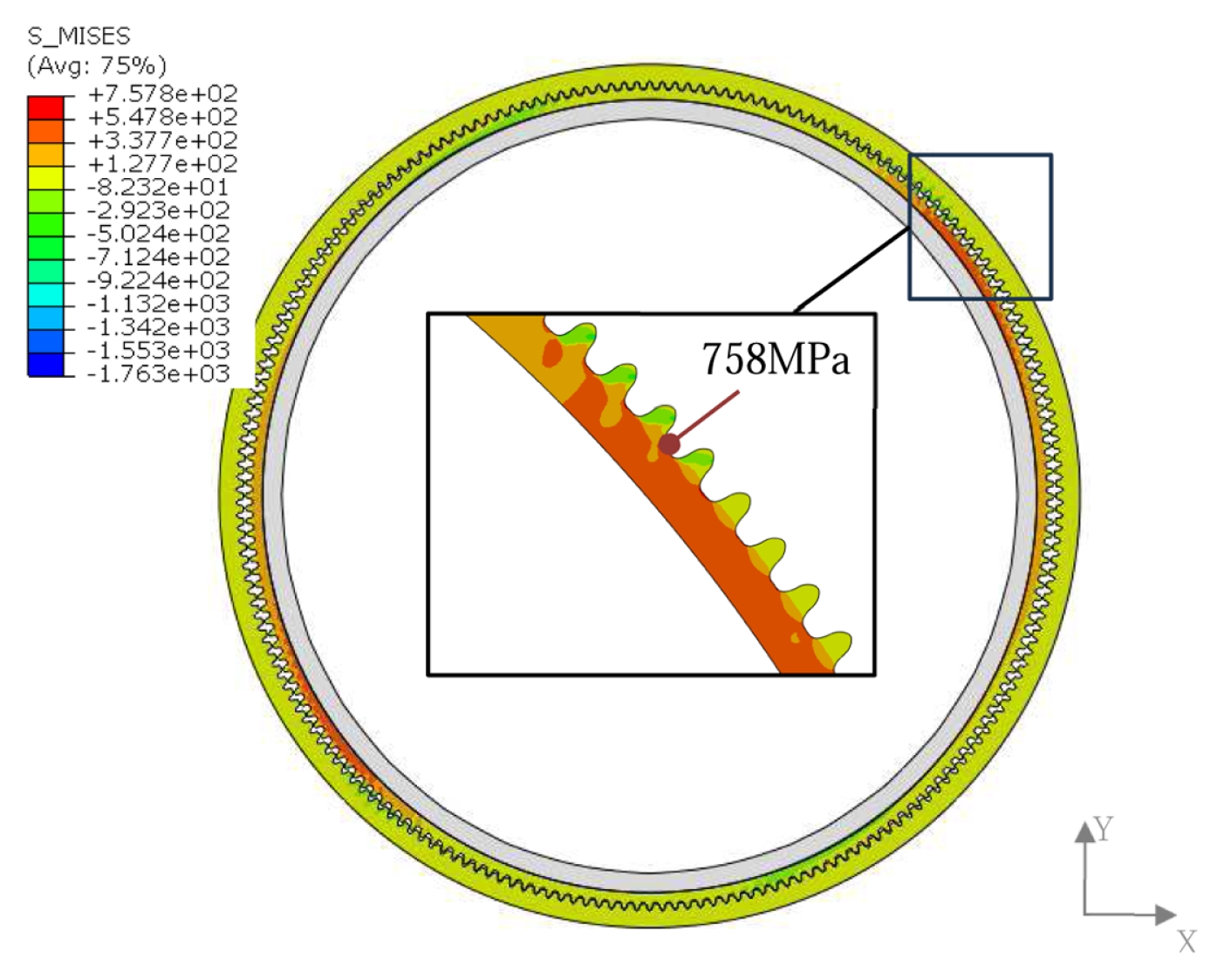
Table 2. To minimize the influence of auxiliary components such as bearings, the wave generator was assumed to be a rigid body. Based on this model, the contact pressure in the tooth contact region and the bending stress at the tooth root were evaluated. The analysis procedure consisted of two steps. In Step 1, the wave generator was inserted into the flex spline. In Step 2, a reference torque of 82 Nm was applied to evaluate the tooth strength under torque loading. Due to the elliptical shape of the wave generator, the maximum stress in the flex spline during Step 1 occurred along the major axis (Y), and the maximum bending stress was 234 MPa. In Step 2, the location of the maximum stress shifted to 45°, and a total of 82 teeth were in continuous contact, with 41 teeth in each of the upper and lower regions relative to the major axis. The maximum bending stress at the tooth root was 758 MPa (
Fig. 7), corresponding to approximately 62% of the material yield strength (1,230 MPa). The maximum tooth contact pressure was 2,277 MPa, indicating a relatively high local contact stress level.
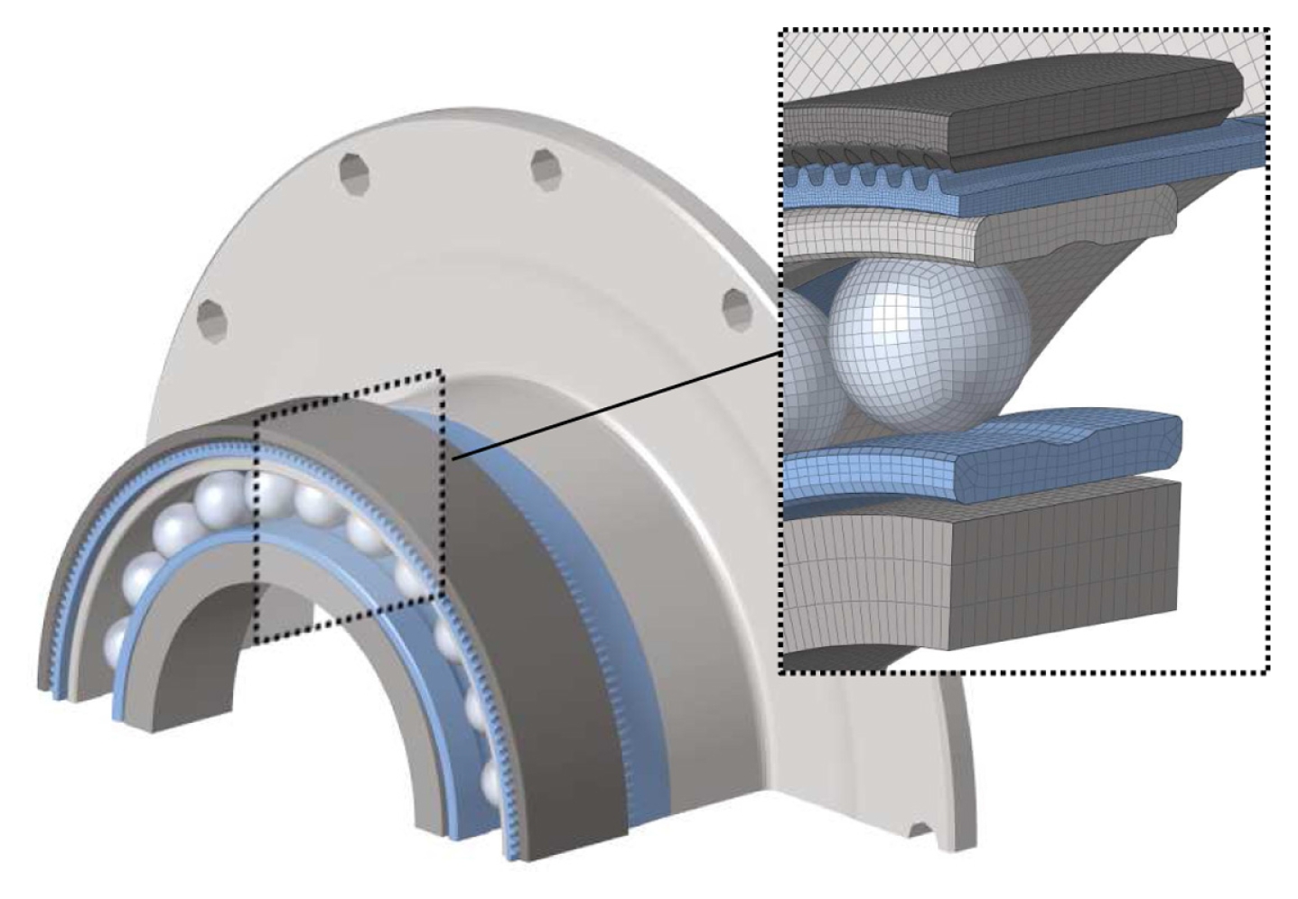
Due to the structural characteristics of the strain wave gear, a coning effect that induces a tilt angle occurs when the bearing is assembled into the flex spline. Since this effect also influences tooth meshing, the tooth contact behavior should be examined with the coning effect considered. In addition, separate contact conditions were defined for the ball-inner race interface and the ball-outer race interface. To reduce the computational cost while taking advantage of model symmetry, a half model of the strain wave gear was developed, as shown in
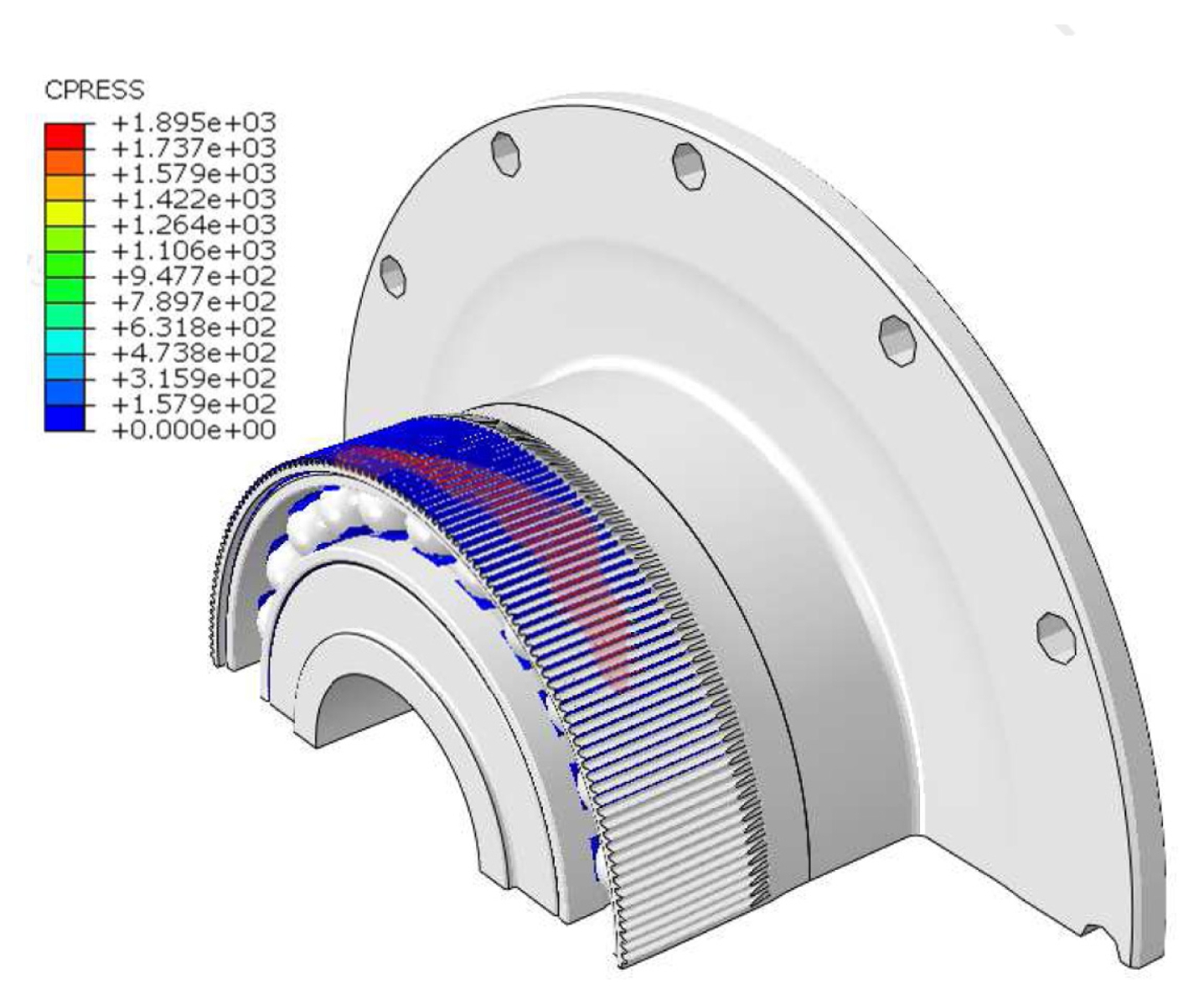
Fig. 8, and a cyclic symmetry boundary condition was applied to the symmetry plane. As in the two-dimensional analysis, the simulation consists of two steps. In Step 1, the coning effect induced by the assembly of the wave generator (WG) is considered. In Step 2, tooth stresses and contact behavior are calculated under an applied torque of 82 Nm. As shown in
Fig. 9, the tooth contact region remained continuous; however, owing to the coning effect, the contact pattern was nonuniform compared with that observed in the 2D analysis. The total number of teeth in contact was 80. The maximum contact pressure and bending stress were 1,895 and 669 MPa, respectively, which are slightly lower than the corresponding 2D analysis results of 2,277 and 758 MPa. These reductions are attributed to the increased contact area and the more distributed load transfer caused by the coning effect.
4. Performance and Load Capacity Tests
The designed strain wave gear was subsequently evaluated in terms of performance and load capacity. In the first step, the gear performance was investigated. In the second step, the load capacity was determined.
4.1 Test Specimen
To validate the proposed design, a strain wave gear sample was manufactured. Considering cycle time and suitability for mass production, power skiving was adopted as the manufacturing process. After manual pairing, the final sample is shown in
Fig. 10. For the load-capacity tests, 18 test samples were manufactured. Tempered 34CrNiMo6 QT steel was used.
However, nine of the samples were manufactured using steel with a lower impurity content, which is expected to result in a higher load capacity.
4.2 Performance Test
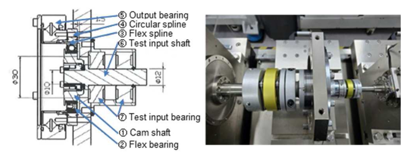
For the performance evaluation of the developed strain wave gear, the specimens were prepared in a semi-unit configuration with test jigs attached to relevant components, such as the output bearing, as shown in
Fig. 11. Performance tests were conducted in accordance with KS B 7300 and KOROS 1166 [
8], including assessments of hysteresis, angular transmission error, transmission efficiency, no-load running torque, and starting torque. A total of nine specimens were tested, and the average values are summarized in
Table 4. The results were compared with the reference specifications [
9], thereby confirming the performance validity of the proposed design.
Load capacity tests were conducted on flex splines made of two variants of 34CrNiMo6 QT steel. Variant A is a conventional grade of 34CrNiMo6 QT steel, whereas Variant B is the same steel grade with a lower impurity content. The aim of the tests was to determine the load capacity of the flex spline tooth root. The load capacity tests were evaluated using the endurance method [
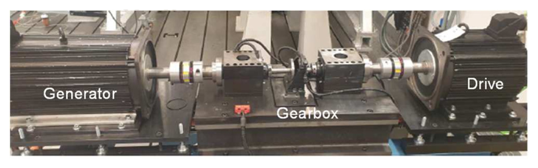
10], with the torque level for each subsequent test adjusted according to whether the previous specimen fractured or resulted in a run-out. The test setup is shown in
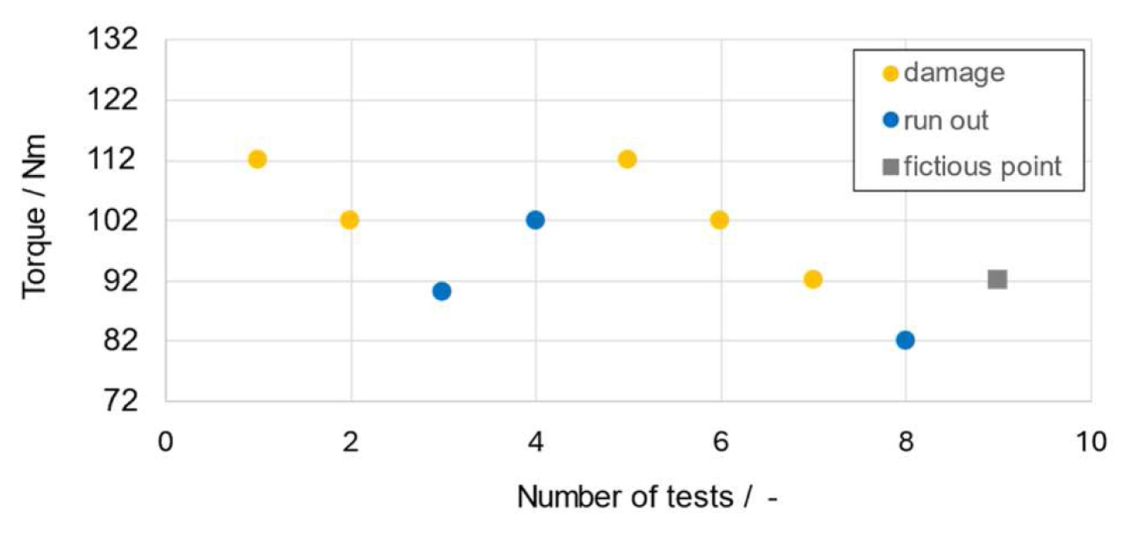
Fig. 12. Grease (Harmonic Grease SK-1A) was applied to the meshing area. The test was stopped when the temperature reached 80°C, abnormal vibrations occurred, or 10⁷ cycles were achieved. The stopping criteria were defined as either reaching the limit of 10⁷ load cycles or the occurrence of fracture or tooth failure, which was identified through vibration monitoring. The results of the load-capacity tests for Variant A are shown in
Fig. 13. The torque corresponding to a 50% failure probability was determined to be T
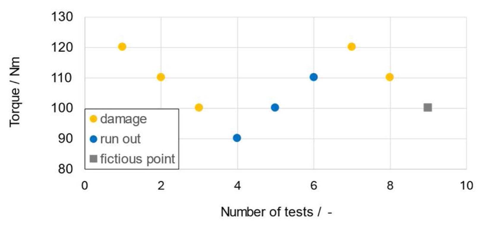
50% = 98.7 Nm. Subsequently, the tests for Variant B were also conducted under the same conditions. The results for Variant B(lower impurity content) are shown in
Fig. 14. The torque for a 50% failure probability was determined at T
50% = 106.7 Nm. This indicates that Variant B, with its lower impurity content, has an 8.1% higher load capacity than Variant A.
5. Conclusion
This study developed and validated the tooth geometry of a strain wave gear through finite element (FE) analyses and experiments.
The results can be summarized as follows:
1) For a strain wave gear with a module of m = 0.254 mm, a 1 : 100 gear ratio, and a 20-inch size, quadruple-circular-arc tooth profiles were designed. The wave-generator deflection was defined as ω = ω₀ cos(2φ) with ω₀ = 0.27 mm, and a MATLAB-based 90° meshing analysis verified interference-free engagement.
2) FE analyses were performed to evaluate tooth-root stress and contact pressure. Under a torque of 82 Nm, the 2D model showed 82 teeth in continuous contact, with maximum values of 758 MPa for root bending stress and 2,277 MPa for contact pressure. The maximum root bending stress corresponds to approximately 62% of the material yield strength (1,230 MPa), indicating a sufficient safety margin in terms of tooth-root strength. The 3D model, which accounted for the coning effect, yielded 80 teeth in contact and a reduced peak contact pressure of 1,895 MPa due to the larger contact area.
3) Finally, nine specimens were used for the performance tests, and 18 specimens were used for the load-capacity tests. The performance metrics satisfied the reference specifications. In the load-capacity tests, the torque corresponding to a 50% failure probability was 98.7 Nm for Variant A and 106.7 Nm for the low-impurity Variant B, corresponding to an 8.1% improvement in load capacity for Variant B. Therefore, the results confirm that the prototype of the developed standard-torque version has sufficient gear strength at the target repeated peak torque of 82 Nm.
Fig. 1Components of the strain wave gear
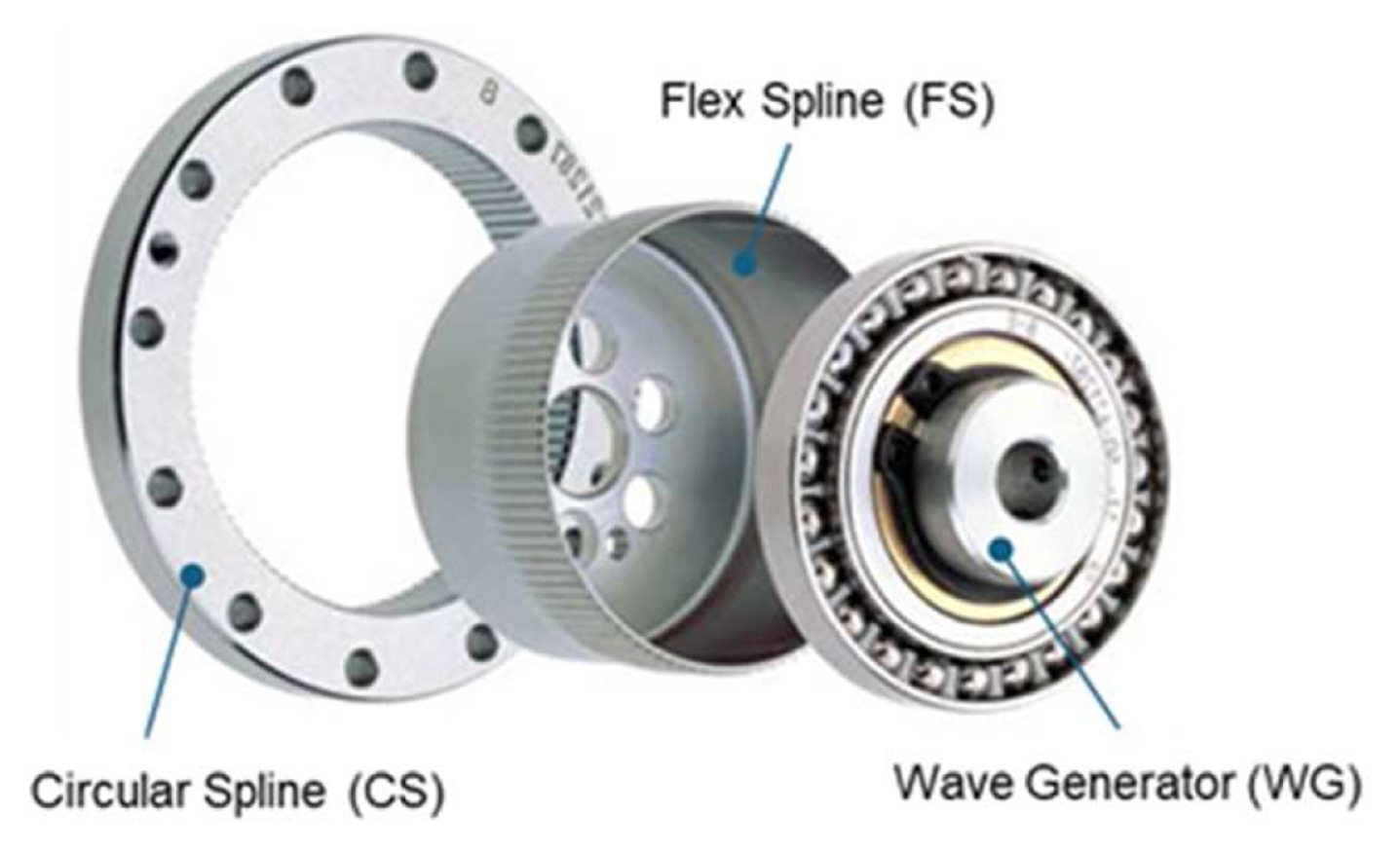
Fig. 2Geometric parameters of the CS and FS
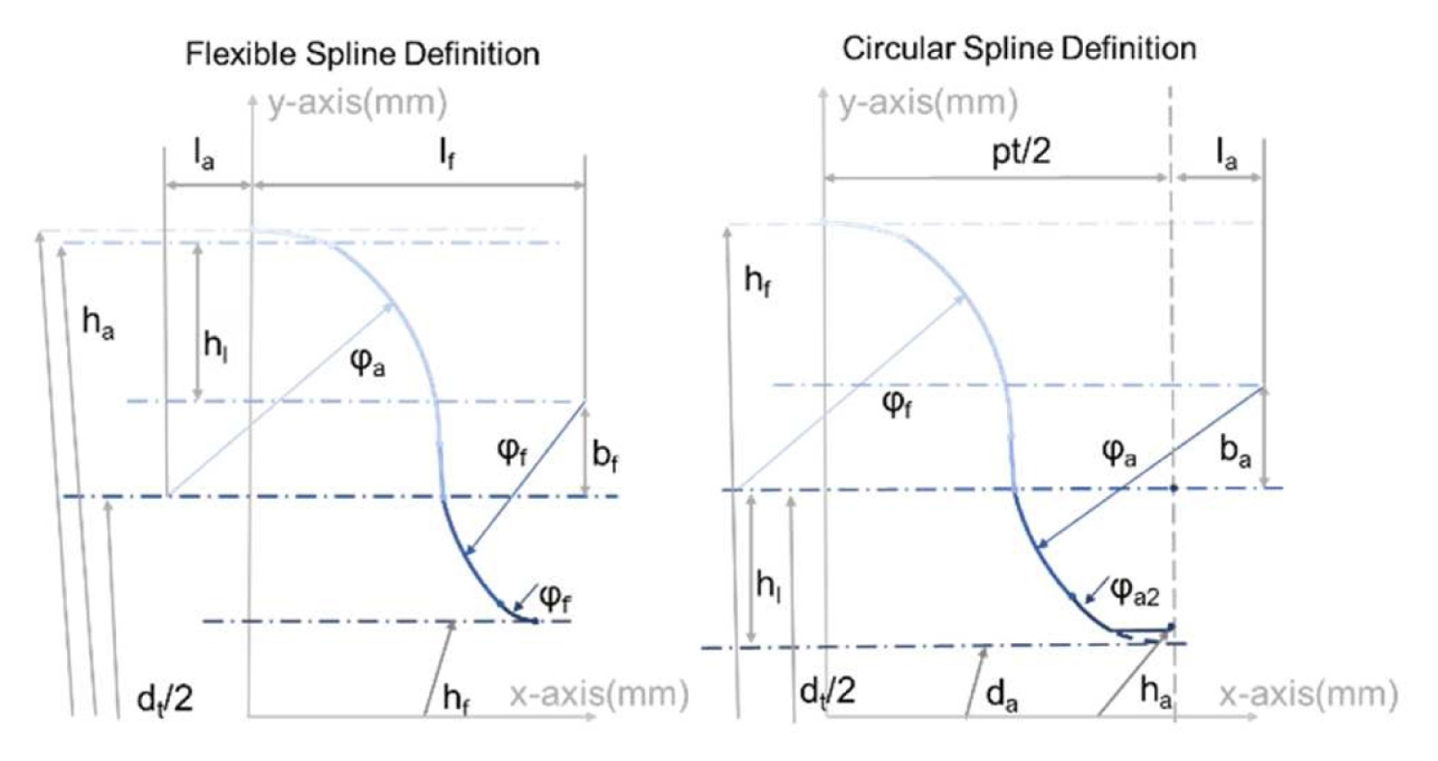
Fig. 3Quadruple-circular-arc profiles of the CS and FS
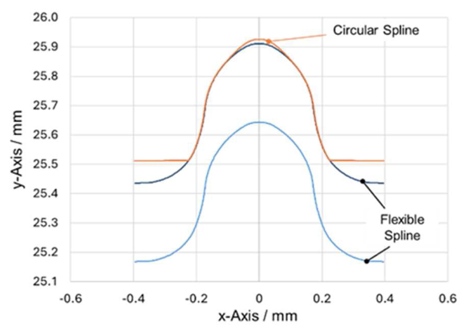
Fig. 4Circumferential variation of the deflection ω in the two force model
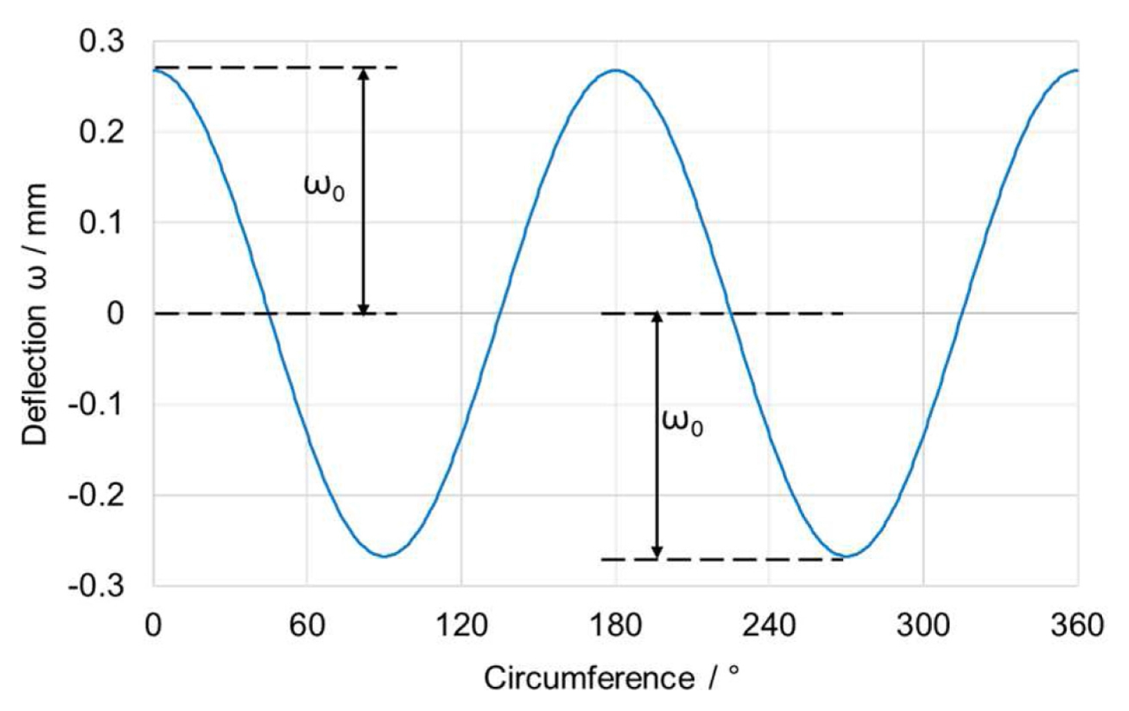
Fig. 5Tooth engagement analysis results
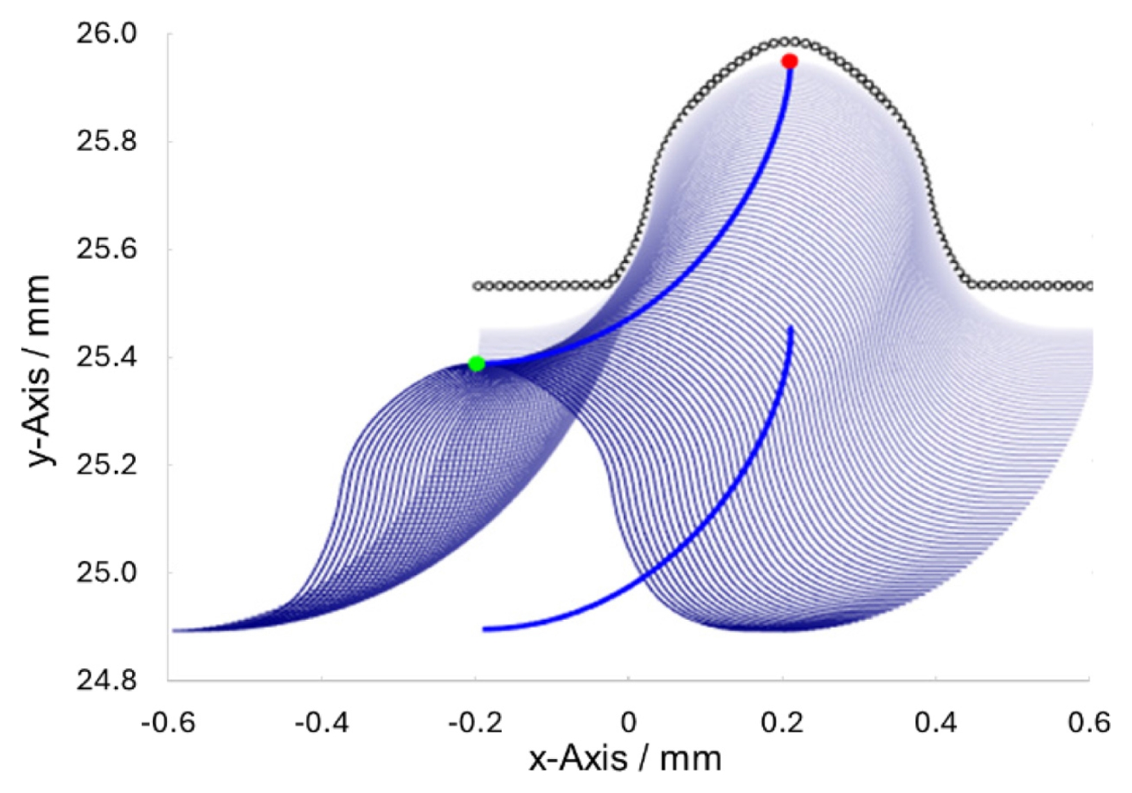
Fig. 62D FE model of the tooth profile
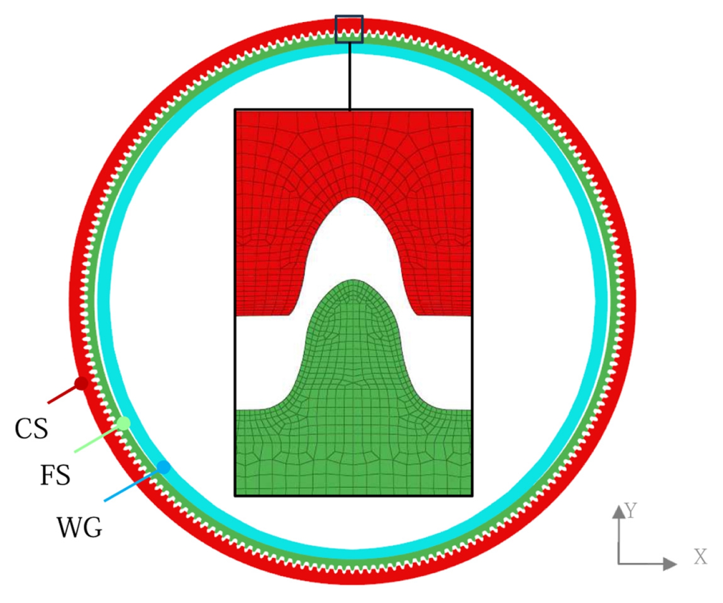
Fig. 7Max. bending (signed von-mises) stress of FS (Step 2)
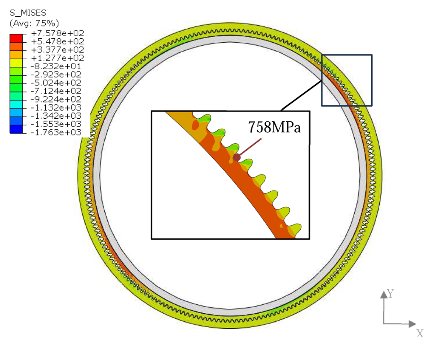
Fig. 8FE model of 3D strain wave gear
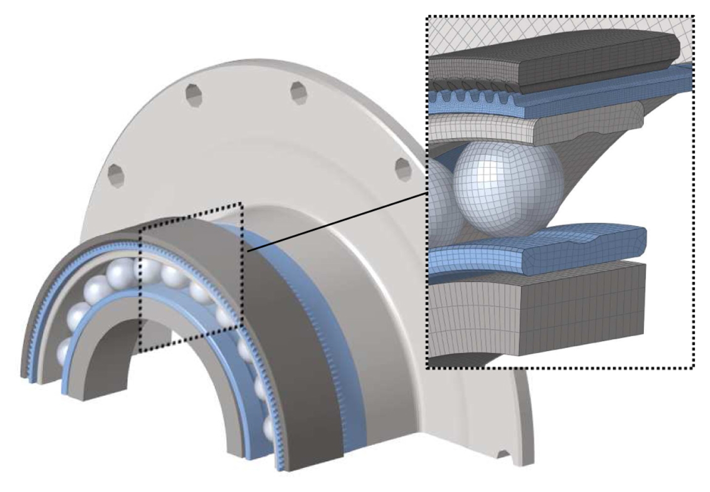
Fig. 9Tooth contact pressure distribution on the flex spline
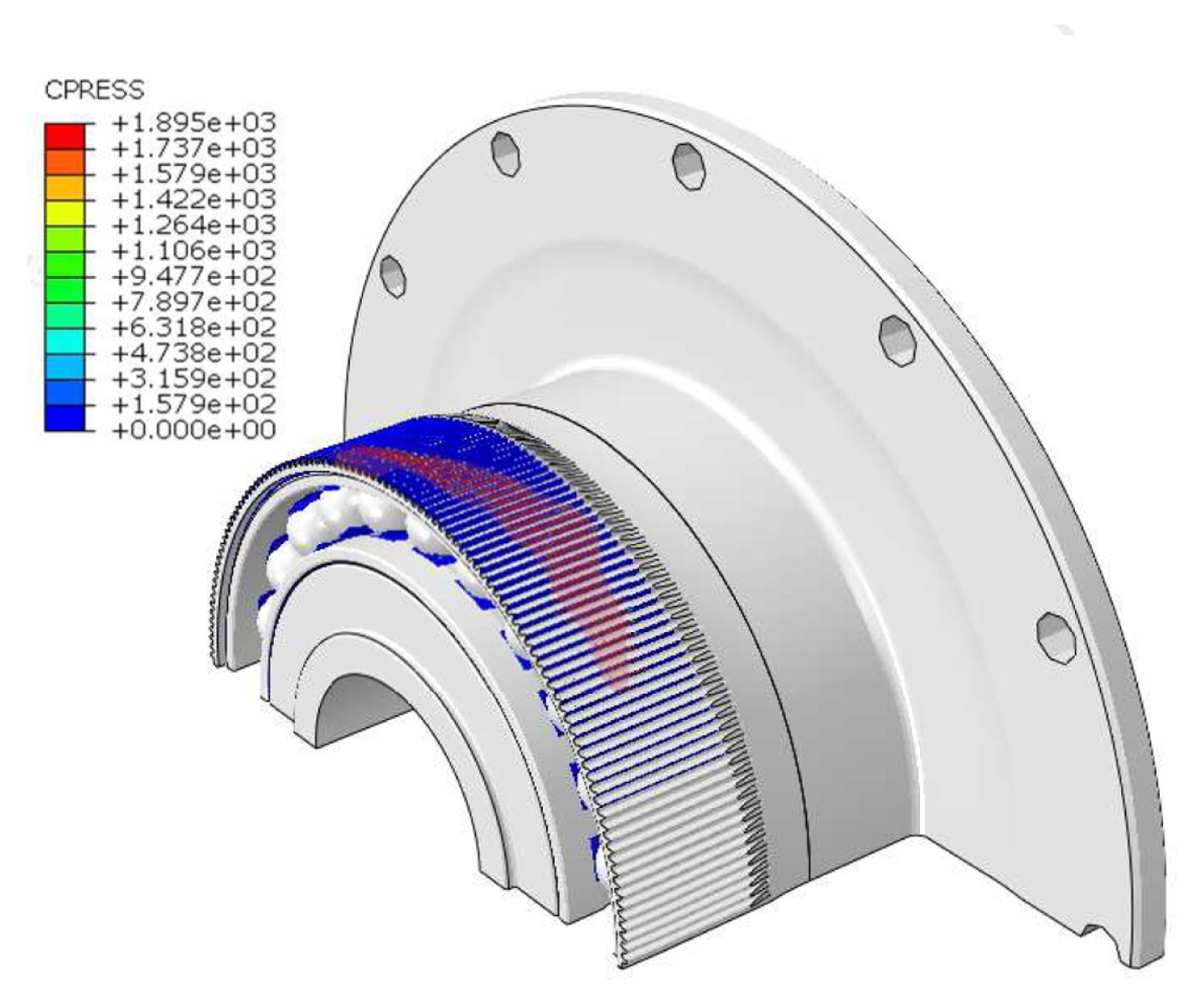
Fig. 10Prototype strain wave gear used for testing
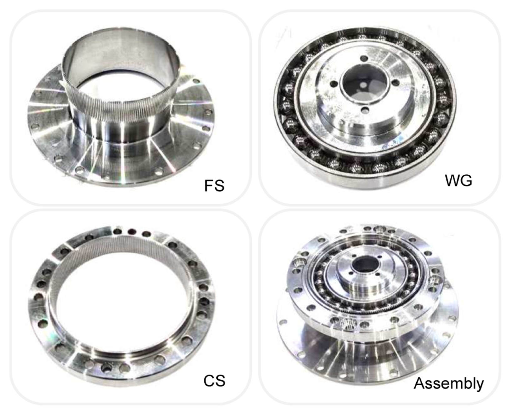
Fig. 11Performance testing set-up
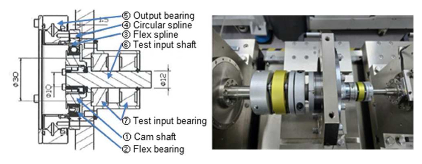
Fig. 12Test setup for load capacity investigation
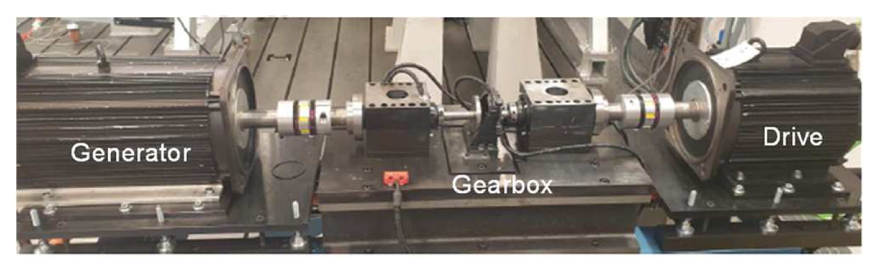
Fig. 13Load-capacity test results for Variant A
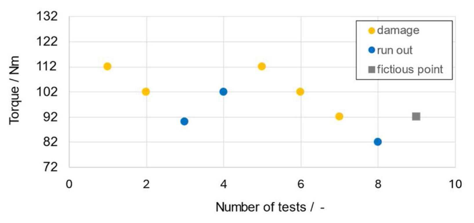
Fig. 14Load-capacity test results for Variant B
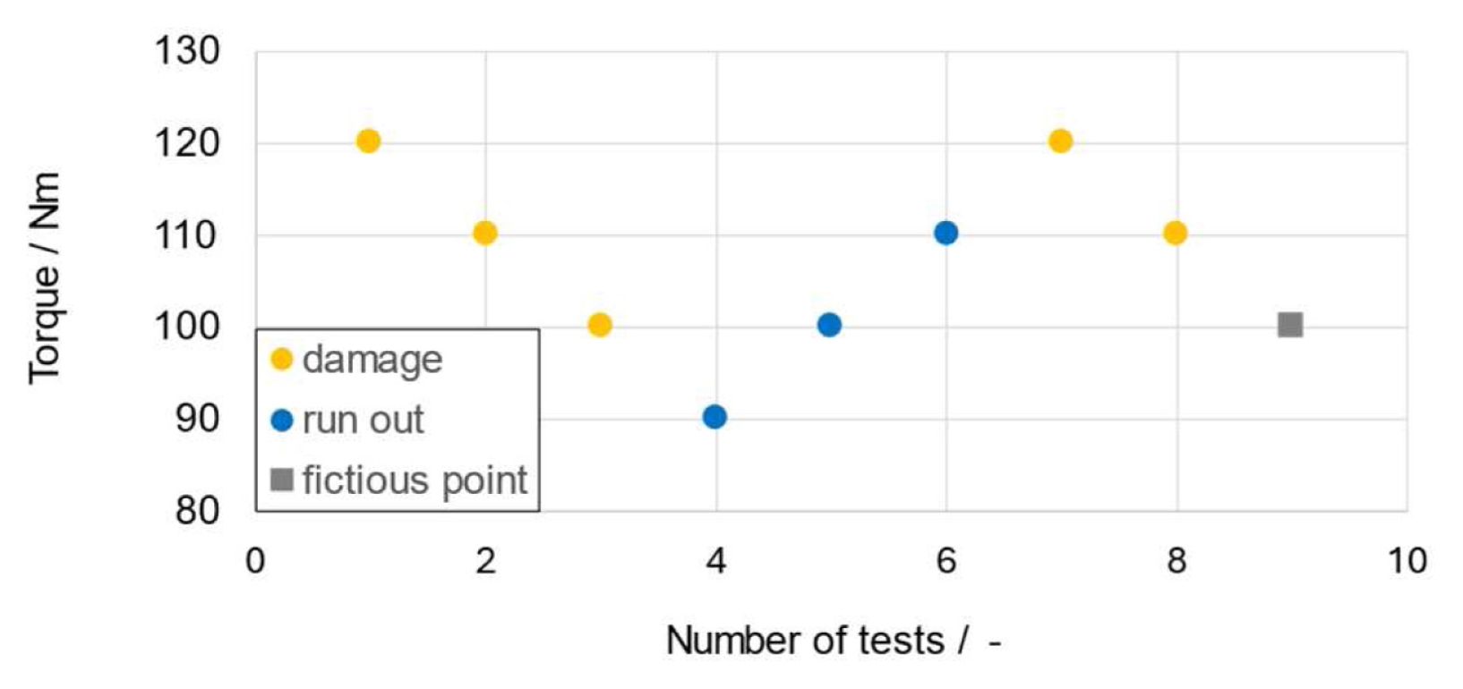
Table 1Main parameters of the designed tooth profiles
Table 1
|
Parameters |
Values [mm] |
Parameters |
Values [mm] |
|
ha
|
0.9 |
ϕf
|
0.21 |
|
hf
|
0.9 |
la
|
0.4 |
|
lf
|
2.72 |
ba
|
0 |
|
bf
|
0.26 |
ϕa
|
1.08 |
|
hl
|
0.76 |
ϕf”
|
0.55 |
Table 2
Table 2
|
Materials |
Young’s modulus |
Poisson’s ratio |
|
42CrMo4 QT (CS) |
160 GPa |
0.3 |
|
34CrNiMo6 QT (FS) |
200 GPa |
0.3 |
|
Steel (WG) |
210 GPa |
0.3 |
Table 3Summary of FE analysis results
Table 3
|
Analysis result |
2-D |
3-D |
|
Contacted tooth number |
82 |
80 |
|
Maximum bending stress [MPa] |
758 |
669 |
|
Maximum contact stress [MPa] |
2,277 |
1,895 |
Table 4
Table 4
|
Test items |
Unit |
Goal [10] |
Result |
|
Hysteresis loss |
arc-min |
1.00↓ |
0.62 (Pass) |
|
Lost motion |
arc-min |
1.00↓ |
0.45 (Pass) |
|
Torsional stiffness |
Nm/arc-min |
8.34↑ |
9.42 (Pass) |
|
Angular transmission error |
arc-min |
1.00↓ |
0.46 (Pass) |
|
Transmission efficiency |
% |
55.0↑ |
68.32 (Pass) |
|
No-load running torque |
Nm |
0.40↓ |
0.12(Pass) |
|
No-load starting torque |
Nm |
0.32↓ |
0.05(Pass) |
REFERENCES
- 1. Ivanov, M. N., (1981), Wave gear transmission. Vysshaya Shkola.
- 2. Zhang, T., Liu, Z., Yang, C., Hu, Q., (2020), Study on the envelope process of the flexspline of harmonic reducer based on the angle of wave generator, IOP Conference Series: Materials Science and Engineering, 012030.
- 3. Cheng, Y.-H., Chen, Y.-C., (2023), A general mathematical modeling and finite element analysis of a strain wave gear possessing a double-circular-arc-with-a-common-tangent profile, Proceedings of the Institution of Mechanical Engineers, Part C: Journal of Mechanical Engineering Science, 237(1):223-236.
- 4. Song, C., Zhu, F., Li, X., Du, X., (2023), Three-dimensional conjugate tooth surface design and contact analysis of harmonic drive with double-circular-arc tooth profile, Chinese Journal of Mechanical Engineering, 36(1), 83.
- 5. Yague-Spaude, E., (2021), Computational design, simulation of meshing, and stress analysis of strain wave gear drives, Ph.D. Dissertation, Rochester Institute of Technology.
- 6. Yu, Z., Ting, K.-L., (2019), Application of finite element analysis for the strain wave gear tooth surfaces design and modification. American Gear Manufacturers Association.
- 7. Yague-Spaude, E., Gonzalez-Perez, I., Fuentes-Aznar, A., (2020), Stress analysis of strain wave gear drives with four different geometries of wave generator, Meccanica, 55(11), 2285-2304.
- 8. KSB 7300;2016, 2016 Test method of high precision reducer for robot.
- 9. Harmonic Drive S. E.. Kataloge - Harmonic Drive® Getriebe. https://harmonicdrive.de/de.
- 10. Hück, M., (1983), Ein verbessertes verfahren für die auswertung von treppenstufenversuchen, Materialwissenschaft und Werkstofftechnik, 14(12), 406-417.
Biography
- Tae Won Kim
Senior Research Engineer, Hyundai-Wia Corporation. His research interests are F. E. Analysis and Development of Precision Mechanical System.
- Christopher Janssen
Senior Research Engineer, Hyundai-Wia Corporation. His research interests are Gear Design and Simulation and Gear Manufacturing.
- Se Chul Jeong
Senior Research Engineer, Hyundai-Wia Corporation. His research interest is Computer Aided Engineering.
- Dong Hyun Choi
Senior Research Engineer, Hyundai-Wia Corporation. His research interest is Precision Manufacturing Engineering.
- Yeon Seok Jeong
Senior Research Engineer, Hyundai-Wia Corporation. His research interests are Driveline System Design and Development.
- Hee Chan Shim
Senior Research Engineer, Hyundai-Wia Corporation. His research interest is Materials Engineering.
- Dal Ho Lee
Senior Research Engineer, Hyundai-Wia Corporation. His research interest is Precision Gear Technology.


 , Christopher Janssen1, Se Chul Jeong1, Dong Hyun Choi1, Yeon Seok Jeong1, Hee Chan Shim1, Dal Ho Lee1