ABSTRACT
This paper presents the design and the control performance of a novel dynamic compliant-arm support with parallel elastic actuators that was developed to assist with the daily living activities of those whose arms are compromised by muscular disease or the aging process. The parallel elastic-arm support consists of a compliant mechanism with combined passive and active components for human interaction and to reach the user’s desired positions. The achievement of these tasks requires impedance control, which can change the virtual stiffness, damping coefficients, and equilibrium points of the system; however, the desired-position tracking by the impedance control is limited when the end-effector weight varies according to the equipping of diverse objects. A prompt algorithm regarding weight calibration and friction compensation is adopted to overcome this problem. A result comparison shows that, by accurately assessing the desired workspace, the proposed algorithm is more effective for the accomplishment of the desired activities.
-
KEYWORDS: Dynamic arm support, Impedance control, Weight calibration
-
KEYWORDS: 팔 기능 지지대, 임피던스 제어, 무게 보정
NOMENCLATURE
Equilibrium position angle setting
Real value of equilibrium position angle
System virtual damping coefficient
Torque by additional weight
1. Introduction
팔 기능 지지대 (Dynamic Arm Support)는 상지의 움직임을 보조하기 위한 기계 장치로 척수손상, 신경근 질환 (Neuromuscular Disease) 및 근위축증 (Muscular Atrophy) 등의 질병이나 혹은 노화로 인한 근육약화로 팔의 기능이 제한되어 불편함을 겪는 사람들의 일상생활동작 (Activities of Daily Living: ADL)을 보조하기 위해 고안된 기구이다.
1 근위축증은 근육에 영향을 주는 유전적 질환으로 근육 약화와 함께 근육 손실이 일어나며 흔히 루게릭병으로 알려져 있는 근위축성 측삭경화증 (Amyotrophic Lateral Sclerosis: ALS), 뒤시엔느 근위축증 (Duchenne Muscular Dystrophy: DMD) 및 척수성 근위축증 (Spinal Muscular Atrophy: SMA)이 그 대표적인 예이다. 이러한 질환을 가지고 있는 환자들은 근육 약화로 인해 식사를 하거나 물체를 들어올리는데 불편함을 겪고 있다.
2 2011년 보건복지부의 조사에 따르면 국내에 지체장애를 가지고 있는 약 137만 명 중, 상지 마비 장애가 있는 인구가 4% 정도이며 이러한 수치는 점차 늘어가고 있는 추세이다.
3
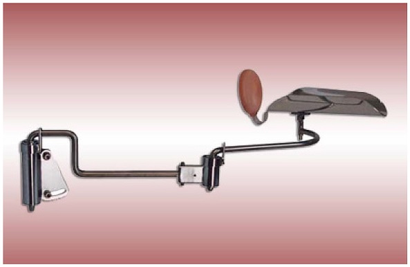
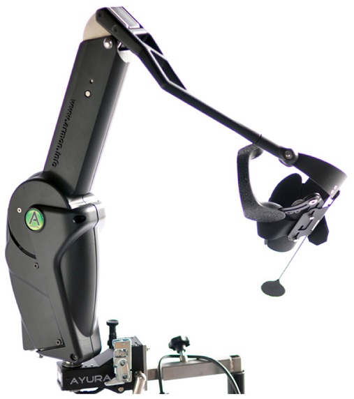
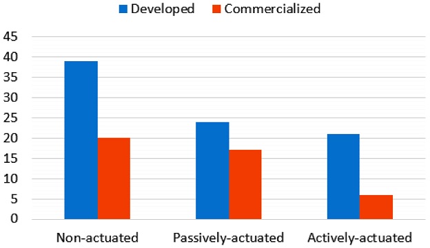
팔 기능 지지대는 작동되는 방식에 따라 비구동형 기구 (Non-Actuated Device), 수동형 기구 (Passively-Actuated Device), 능동형 기구 (Actively-Actuated Device)로 분류된다. 비구동형 기구는 추가적인 동력원 없이 구조적으로만 팔의 무게를 지탱하기에 사용자는 수평 방향의 움직임만이 가능하다. 수동형 팔 기능 지지대는 균형추, 스프링 등의 기계요소를 사용하여 위치 에너지를 이용해 중력으로부터 팔을 지탱하고 사용자가 적은 근력으로도 움직이도록 도와준다. 구동기나 센서를 이용하는 능동형 팔 기능 지지대는 외부 에너지를 이용하여 수직 방향의 운동 보조 기능을 수행할 수 있다. 2012년까지 전세계적으로 97개의 팔 기능 지지대가 존재하며, 이 중 비구동형 기구가 39개 (e.g. Standard Mobile Arm Support, JAECO Orthopedic,
Fig. 1), 수동형 기구가 24개 (e.g. Mobility Arm, Nitzbon) 능동형 기구가 21개 (e.g. Armon Ayura, Armon Products,
Fig. 2)이다. 그렇지만 상용화된 제품은 비구동형 기구가 20개(51%), 수동형 기구가 17개(71%), 능동형 기구가 6개(18%)로 비구동형 기구나 수동형 기구에 비해 큰 크기와 높은 가격 문제로 인해 능동형 기구의 상용화 비율과 사용도가 낮다 (
Fig. 3,
Table 1).
1
Fig. 1 Standard mobile arm support, JAECO orthopedic1

Fig. 2

Fig. 3 Numbers of non-actuated, passively-actuated and actively-actuated arm supports1

Table 1 Weight of the actively-actuated arm supports
Table 1
|
Actively-Actuated |
Total weight |
|
Armon ayura |
6 kg4
|
|
DAS |
4.9 kg5
|
팔 기능 지지대는 사용자가 원하는 움직임을 보조할 수 있어야 하며 사용자와 직접적으로 맞닿아 작동하기에 안전한 인간-로봇 상호작용 (Human-Robot Interaction)을 위해서는 강성이 작은 유연한 구조가 적합하다.
6 하지만 기존의 수동형 팔 기능 지지대는 중력 보상만으로 팔을 지탱하기에 사용자가 높이 방향 위치를 바꾸기 위해서는 탄성력에 저항하여 더 큰 힘을 가해야 한다. 따라서, 팔 근력이 없거나 약한 환자는 수직 방향으로 움직이기 힘들다. 반면 능동형 팔 기능 지지대는 구동기로 위치 조절하는 것이 가능하나, 대부분의 경우 힘 센서 없이 위치 제어로 정확하게 각도 조절을 하기 위해 큰 기구 강성을 가진다.
1
본 연구에서는 이러한 기존의 팔 기능 지지대의 단점을 보완하고 사용자가 원하는 위치로 도달하기 위해 수동형 팔 기능 지지대와 능동형 팔 기능 지지대의 특성을 결합한 평행 탄성(Parallel Elastic) 엑츄에이터 형태에 임피던스 제어 (Impedance Control)을 적용한 팔 기능 지지대를 제안한다.
7 본 팔 기능 지지대는 스프링과 모터를 사용하여 수동적인 유연함 (Passive Compliance)을 구현한다. 이러한 유연한 구조는 순간적인 충격을 흡수할 수 있어 기존의 강성이 높은 구조보다는 사용자가 안전하게 사용할 수 있으며 에너지 저장 측면에서도 유리하다.
8
임피던스 제어는 엑츄에이터가 임피던스 거동을 모사하도록 하는 제어 방식으로 기구의 강성 (Stiffness)과 감쇠 계수 (Damping Coefficient)를 변경할 수가 있다. 이러한 방식은 정확한 시스템 동역학 모델을 필요로 하지만 기구의 평형점과 시스템의 특성을 조절할 수 있다는 장점이 있다.
9
하지만 시스템의 강성과 감쇠 계수를 조절하는 임피던스 제어만으로는 팔 기능 지지대의 단말작동기 (End-Effector)에 장착되는 팔과 물체를 들게 되어 추가되는 무게를 충분히 보상할 수가 없어 설정한 평형점과 실제 평형점과의 평형 상태 오차가 발생한다. 상지 시스템은 섬세한 동작과 일상생활 보조가 가능해야 한다는 사용자의 요구를 만족시키기 위해서는 이러한 평형 상태 오차를 감소시키는 방안이 필요하다.
10 따라서 본 연구에서는 임피던스 제어와 추가되는 무게를 즉각적으로 보상하는 알고리즘과 마찰력 보정을 통해 어떠한 물체가 착용되더라도 설정된 평형점(
θeq)에 도달할 수 있도록 하는 무게를 보정하는 알고리즘을 구현하여 사용자가 원하는 작업공간에 정확하게 도달하도록 한다.
2. Design & Modeling
2.1 Design
수동형 팔 기능 지지대와 능동형 팔 기능 지지대의 단점을 보완하고 특성을 결합하고자 본 연구에서는 상용화된 Armon Products사의 Armon Edero
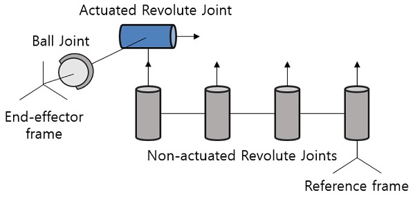
11 형상을 참고하여 수동형 팔 기능 지지대에 모터를 부착한 팔 기능 지지대를 설계하였다. 총 5개의 회전 조인트와 1개의 볼 조인트로 구성되어 7 자유도를 가지며 z축을 중심으로 회전하는 4개의 조인트는 비구동형으로 사용자의 수평 방향 움직임을 보조한다. 수직 방향의 움직임은 모터와 스프링이 연결되어 있는 회전 조인트로 제어하며, 기구의 링크와 말단작동기는 볼 조인트로 연결된다 (
Fig. 5).
Fig. 4Classification of the arm support
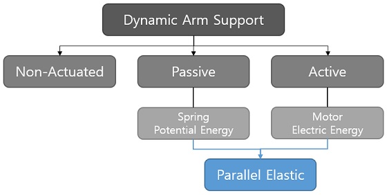
Fig. 5Schematic of the arm support
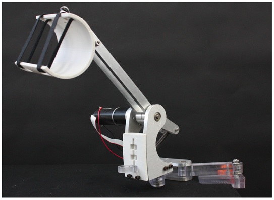
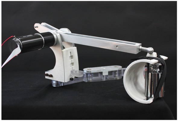
본 팔 기능 지지대는 CNC로 가공한 폴리카보네이트 (Polycarbonate) 및 알루미늄 파트와 FDM 프린터로 제작한 PLA (Poly Lactic Acid) 파트로 구성되어 있다 (
Fig. 6,
Table 2). 모터와 스프링이 병렬적으로 연결되어 있는 유연한 구조를 이용하여 기구 사용 중에 팔이 벽이나 물체에 부딪히더라도 외부로부터의 충격에 치명적이지 않도록 하였다.
5 본 기구는 지정된 위치에서 사용할 수 있도록 견착형으로 설계 되어 책상 및 휠체어에 장착 가능하다.
Fig. 6Parallel elastic arm support

Table 2Electronics and structure specifications
Table 2
|
Components |
Model |
Specification |
|
Motor |
Maxon DC motor
148867 |
150W
Continuous maximum
torque = 4.6 Nm |
|
Gear |
Planetary gearhead |
Gear ratio = 26:1 |
|
Parts |
Polycarbonate,
aluminum,
PLA |
Maximum length = 650 mm
height = 180 mm
device link length = 270 mm |
|
Weight |
- |
2.62 kg |
2.2 Modeling
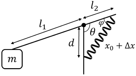
팔 기능 지지대에서 모터와 스프링에 의해 움직이는 회전 관절 부분 (Actuated Revolute Joint)의 모식도를
Fig. 7에 나타내었다. 기구의 단말작동기에 추가되는 질량을 m, 중심축으로부터 단말작동기 사이의 거리를
l1, 중심축으로부터 스프링까지의 거리를 각각
l2,
d로 나타내었다.
θ는
l2,
d가 이루는 각도,
ϕ는
l2와 스프링이 이루는 각도를 의미한다.
x는 스프링 길이로,
Δx는 스프링 길이의 변화량,
x0는 스프링 초기 길이를 의미한다.
Fig. 7Model of a parallel elastic arm support
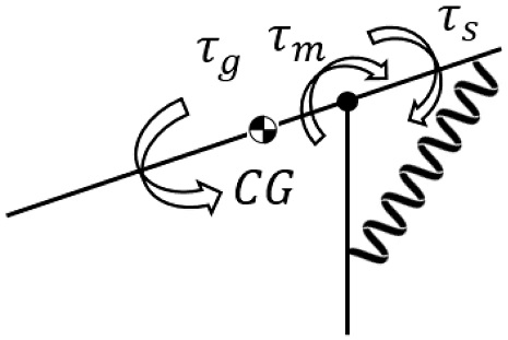
스프링의 복원력에 의한 토크를
τs, 기구 자체 무게로 인해 발생하는 토크를
τg, 모터 구동에 의한 토크를
τm이라 할 때, 설계한 기구의 시스템은
식(1)로 나타난다 (
Fig. 8).
Fig. 8Torque diagram of a parallel elastic arm support
2.2.1 Spring Torque (τs)
스프링 토크는 스프링의 복원력에 의해 기구 팔에 가해지는 토크를 의미한다. 기구 모델에서 팔 기능 지지대의 회전각도
θ에 따른 스프링의 탄성력 및 토크는 기하학적인 구조를 바탕으로 계산된다. 스프링 토크는 사용자 팔의 중력을 보상해주는 역할을 수행하며
식(2)부터
식(4)에 의해
θ에 대한 함수로 표현된다.
2.2.2 Gravity Torque (τg)
기구 자체의 중력으로 인한 토크는 모델링을 바탕으로 추정한다. 중력에 의한 토크는
식(5)의 삼각함수 형태로 나타나며 계수 A를 실험적으로 측정한다. 측정 방식은 모터가 기구 각도 (
θ)에 따라
식(5)의 삼각함수 형태로 토크를 가하게 한 후, 계수 A를 변화시켜가면서 아무 것도 장착되어 있지 않은 기구가 중력과 평형을 이루게 하는 계수를 찾는다. 그 결과, 본 기구에서 계수 A는 약 1.17 Nm로 나타난다.
2.2.3 Motor Torque (τm)
팔 기능 지지대에 부착되어 있는 모터로 기구 각도 움직임을 조절한다. 모터에서 발생하는 토크가 사용자 팔의 중력을 보상해주며 단말작동기의 위치를 조절한다.
3. Control Design
3.1 Impedance Control
본 연구에서는 사용자가 원하는 시스템의 가상의 강성 (Virtual Stiffness)과 가상의 감쇠 계수 (Virtual Damping Coefficient)를 조절하고 평형점 이동으로 사용자가 원하는 작업공간의 확장을 위해 임피던스 제어를 적용하였다.
12 이러한 제어 방식을 통해 사용자가 팔 근력을 적게 사용하거나 근력이 없더라도 원하는 위치로의 도달이 가능하다. 임피던스 제어를 적용한 시스템 모델은
식(6)으로 표현된다.
Kr: Virtual Stiffness
Cr: Virtual Damping Coefficient
팔 기능 지지대의 스프링 토크와 중력에 의한 토크를 바탕으로 모터는 설정한 가상의 강성
Kr와 가상의 감쇠 계수
Cr로 기구의 특성을 조절한다. 입력 (
u)으로
식(7)에서 구한 모터 토크를 가해 설정한 평형점 (
θeq)으로 도달하게 하여 위치 이동을 한다.
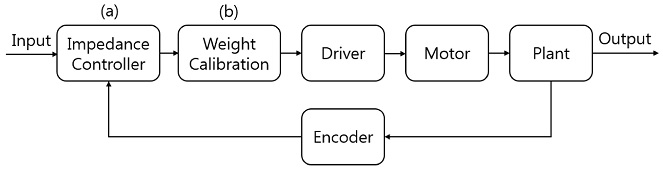
Fig. 9Control algorithm of the system which consist of impedance controller: (a) and weight calibration algorithm, (b) Inout: Kr, Cr, θeq, Output: ϕ
3.2 Design Parameter Selection
팔 기능 지지대의 중력 보상을 위한 스프링 상수 (k)를 결정하기 위해 기구 각도에 따라 필요한 모터 토크를 계산하여 모든 각도로 가동이 가능하기 위한 조건들을 확인해야 한다. 계산을 위한 시뮬레이션 조건은 Kr = 2 N/m, θeq = 1.6 rad, m = 1.5 kg으로 설정되었다. 허리 높이의 팔 받침대가 있는 휠체어 혹은 의자에 팔 기능 지지대를 설치하고 성인의 전완 무게를 지탱하여 책상 위에서 글쓰기 등의 작업을 가정하여 각도와 무게 변수들을 선정하였다.
기구 각도
θ가 변함에 따라 스프링과 중력에 의한 토크가 달라지기 때문에
식(7)에 의해 각도에 따라 모터 토크도 변한다. 가동 가능한 모든 각도에 대해서 중력 보상이 가능하기 위해서는 모터가 지속적으로 발생시킬 수 있는 토크가 계산된 토크의 상한보다 커야 한다.
또한 모터 구동으로 인한 각도 제어가 용이하도록 스프링 상수를 선정해야 한다. 각도에 따른 모터의 토크 변화가 작으면 입력으로 임피던스 제어를 통해 계산된 모터 토크를 가하더라도 목표값에서 부정확한 출력 값이 나타날 가능성이 커진다. 따라서, 설정한 평형점에 정확하게 도달하기 위해 각도 변화에 따라 모터 토크의 차이가 큰 그래프를 선정하여 스프링 상수를 결정해야 한다.
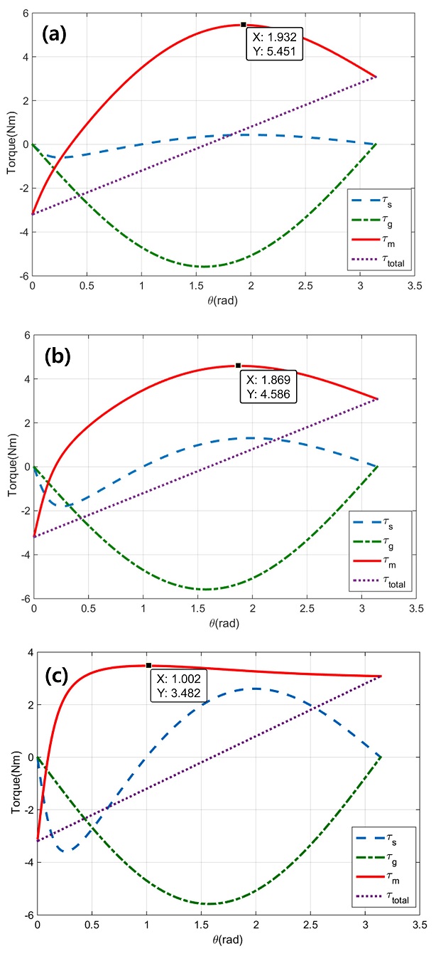
현 조건 상에서 최적의 스프링 상수를 결정하기 위한 대표적인 시뮬레이션 결과를
Fig. 10에 나타내었다.
Fig. 10의 그래프는 각각 스프링 상수가 200 N/m, 600 N/m, 1200 N/m일 때의 스프링 토크, 중력에 의한 토크, 모터 토크를 각각
식(2),
식(5),
식(7)을 이용하여 도시한 결과이다.
τtotal은
식(6)을 이용하여 나타내었다.
Fig. 10Simulation results of exerted torque to the system within the workspace: (a) k = 200 N/m, (b) k = 600 N/m, (c) k = 1200 N/m

스프링 상수가 600 N/m보다 작은 경우, 최대로 필요한 모터 토크가 현 기구의 모터 사양인 4.5 Nm보다 커져 모든 각도의 가동이 불가능해진다 (
Fig. 10(a)). 반면, 스프링 상수가 1200 N/m 근방인 경우, 각도에 따른 모터 토크 변화가 거의 없어 원하는 각도로의 이동이 어렵다 (
Fig. 10(c)). 즉, 스프링 상수는 600 N/m보다 커야 하며, 스프링 상수가 커질수록 작동 범위 내의 모터 토크 그래프의 기울기가 작아져 각도 제어가 어려워지므로 가능한 작은 스프링 상수를 선정해야 한다.
따라서 위 조건을 만족하는 스프링 상수 중, 가장 작은 값인 스프링 상수
k = 600 N/m를 선정하였다 (
Fig. 10(b)). 모터 사양 및 초기 조건이 달라지더라도 이러한 방법을 통해 기능 수행에 필요한 스프링 상수 선정이 가능하다.
팔 기능 지지대는 사용자가 착용하거나 물건을 집는 어떠한 상황에서도 사용자의 의도에 맞는 작업 공간에 도달해야 한다. 그렇지만 본 연구에서 적용한 임피던스 제어만으로는 전완의 무게가 다른 다양한 사용자가 착용하거나 사용자가 숟가락이나 물컵을 드는 경우처럼 집는 물체의 무게가 달라질 때에는 원하는 위치로의 정확한 이동이 불가능하다. 힘 센서 없이는 중력에 의한 토크를 측정할 수가 없어 임피던스 제어는 다양한 물체가 장착될 때 추가되는 중력을 배제한 기구의 모델링을 바탕으로 구현된다. 따라서 단말작동기에 물체가 더해진 경우, 중력에 의한 토크가 증가하기 때문에 사용자가 설정한 작업 공간보다 낮은 공간으로 기구가 도달하게 된다.
이를 극복하기 위해 본 연구에서는 추가적인 무게를 보상하는 알고리즘을 고안하였다. 정적 평형 상태의 평형점 (
ϕ)과 설정된 평형점 (
θeq) 간의 각도 차이를 측정하여
식(8)부터
식(12)을 통해 단말작동기에 가해지는 토크를 추정한다. 그 후, 이에 해당하는 추가적인 토크를 모터로 가하여 추가되는 무게로 인한 오차를 보정할 수 있다.
본 팔 기능 지지대의 동역학 모델을
식(8)과
식(9)로 구할 수 있다.
τadd는 추가된 무게로 인한 토크를 의미한다.
정적 평형상태인 경우, 각속도와 각가속도가 0이며 θ¨=0, θ˙=0, 이 때 단말작동기에 추가되는 무게로 인한 새로운 평형점을 ϕ라 한다. 평형상태오차는 이론적 평형점과 실제 평형점 간의 각도 차이(θeq−ϕ)로 나타난다.
식(8)과
식(9)에 정적 평형상태 조건
θ¨=0, θ˙=0을 대입하면
식(10)부터
식(12)을 통해 추가되는 토크를 추정하여 무게 보정을 위한 입력 (
ucal)을 구할 수 있다(
식(13)). 따라서 무게 보정 알고리즘을 통하여 얻어낸 총 입력 (
utotal)은
식(14)와 같다.
따라서 기구가 평형점에 도달하여 평형상태오차를 측정하여 추가되는 토크를 추정한 뒤, 이에 해당하는 토크를 더 가해 최종적으로는 사용자가 설정한 평형점 θeq로 도달할 수가 있다.
3.4. Friction Compensation Algorithm
보다 정확하게 원하는 위치로 도달하기 위해서는 축에서 발생하는 마찰력도 고려해야 한다. 모터 축에서 발생하는 운동 마찰력은 질량과 각도에 의한 함수 f(m, θ)로 나타낼 수 있다. 쿨롱 마찰력 (Coulomb Friction)은 수직항력에 비례하기에 무게를 추가함으로써 발생하는 추가적인 마찰력은 τadd에 비례한다고 가정하며 점성 마찰 (Viscous Friction)은 무시한다.
마찰 보정까지 더해 최종적으로 모터가 가해주는 토크 보정값 (
uf)은
식(17)과
식(18)로 나타난다.
4. Experimental Result
4.1 Impedance Control
임피던스 제어의 성능 평가를 위해 팔 기능 지지대의 설정된 평형점(
θeq= 2 rad)에서 1 kg의 추를 매달았을 때 (
Fig. 11) 가상의 강성 및 가상 감쇠 계수 변경에 대한 시간에 따른 각도 변화를 모터 엔코더를 통해 측정하였다 (
Figs. 12와
13). 하드웨어는 LabVIEW를 이용하여 제어하였다.
Fig. 11Experiment setup

Fig. 12Experiment results of the various virtual stiffness, Kr

Fig. 13Experiment results of the various virtual damping coefficient, Cr
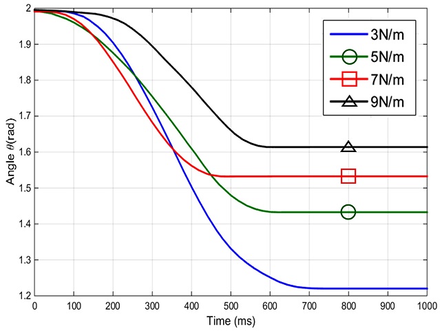
임피던스 제어를 통해 기구의 가상 강성을 변경할 수가 있다. 강성이 클수록 외란에 의해 움직이는 변동이 작으며, 강성이 작을수록 외란에 의한 변동이 크다. 시스템 상의 단말작동기에 추가된 무게에 대한 고려가 되지 않았으므로 실제 평형점 (
θeq)과 설정된 평형점 (
ϕ) 간의 차이인 정상상태 오차가 발생한다. 정상상태 오차가 시스템의 강성이 클수록 감소하는 경향을 보이며 이로 임피던스 제어를 통한 가상의 강성 조절이 잘 수행되었음을 확인할 수 있다 (
Table 3).
Table 3Comparison of steady state error
Table 3
|
Kr (N/m) |
3 |
5 |
7 |
9 |
|
θeq − ϕ(rad) |
0.780 |
0.567 |
0.468 |
0.386 |
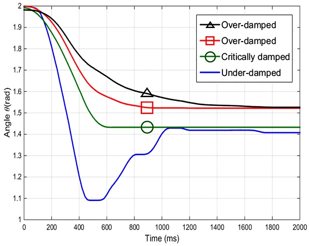
또한 가상 감쇠 계수 Cr를 변경함에 따라 시스템의 거동 특성을 조절할 수 있다. 가상 감쇠 계수 Cr = 0인 경우, 부족제동(Under-Damped) 특성이 나타나며 점차 Cr를 증가시킴에 따라 임계제동 (Critically Damped), 과제동 (Over-Damped) 특성이 나타난다.
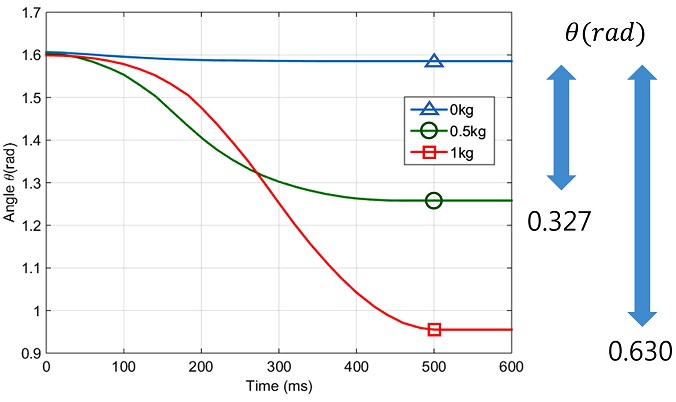
Fig. 14는 500 g, 1 kg의 설정된 목표 평형점(
θeq = 1.6 rad) 상태에서 추를 기구에 연결하여 목표 지점까지 이동하게 하는 임피던스 제어를 적용했을 때의 결과이다. 500 g 무게가 추가되면 사용자가 설정한 평형점 (
θeq)과 실험에서 구한 평형점과 0.327 rad의 차이가 생기며 1 kg의 무게가 추가되면 0.630 rad의 차이가 발생한다. 즉, 추가적인 무게가 가해졌을 때 정상상태 오차가 커지며, 이는 무게가 증가할수록 비례하여 증가한다. 따라서 팔 기능 지지대의 요구 기능을 만족시키기 위해서는 추가적으로 가해지는 무게를 보정하기 위한 제어 방식이 필요하다.
Fig. 14Steady state error occurs by additional weight
4.2 Weight Calibration
무게 보정 알고리즘의 평가를 위해
식(17)과
식(18)를 적용하여 팔 기능 지지대의 단말작동기에 각각 500 g, 1 kg의 추를 매달고 기구를 작동시켰다. 바닥 상태 (0.5 rad)에서 설정된 평형점(
θeq = 1.6 rad)까지의 시간에 따른 각도 변화 관계를 측정하여 도시하였다 (
Figs. 16과
17).
Fig. 15Weight calibration process
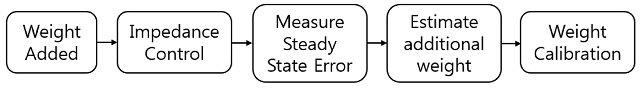
Fig. 16Angle trajectory following with the impedance control and weight calibration (500g weight, equilibrium angle: 1.6rad)

Fig. 17Angle trajectory following with the impedance control and weight calibration (1kg weight, equilibrium angle: 1.6rad)

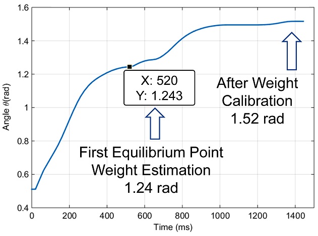
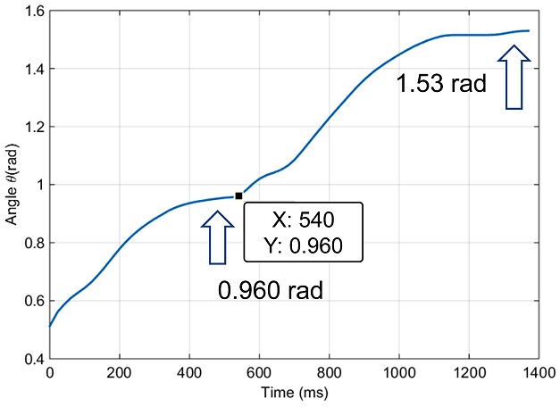
Figs. 16과
17은 각각 500 g, 1 kg의 추를 매달았을 때의 시간에 따른 각도 변화 그래프이다. 실험 결과 그래프에서 두 번의 평형(각속도 = 0)이 이루어진다. 추가되는 무게로 인한 토크를 측정하기 위해 500 - 600 ms 구간에서 나타나는 첫 번째 평형점 (
ϕ) 이전 구간에서는 임피던스 제어만 시행된다. 그 후, 첫 번째 평형점에서
식(12)에 의해 추가된 무게로 인한 토크를 측정하고
식(17)과
식(18)에 의해 즉각적으로 보정된 모터 토크를 가하게 되어 최종적으로 설정된 평형점
θeq에 도달하게 된다. 입력되는 무게가 바뀌어도 첫 번째 평형점 (
ϕ)은 다르지만 최종적으로 기구가 도달하는 지점 (
θeq)은 일정하다는 것을 확인할 수 있다. 위 실험으로 얻어낸 각도 변동 결과는 목표 값과 약 5% 오차를 나타낸다. 이는 무게 보정 알고리즘을 적용하기 전의 임피던스 제어만 적용하였을 경우의 오차보다 500 g일 때는 24%, 1 kg일 때는 11%로 감소한 수치이다.
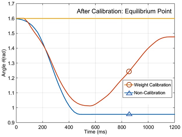
임피던스 제어만 시행했을 때와 무게 보정 알고리즘까지 시행 했을 때와의 개형 비교를 위해 시간에 따른 각도 변화 관계를 측정하여 도시하였다 (
Figs. 18과
19). 설정된 평형점 (
θeq= 1.6 rad) 단말작동기에 각각 500 g, 1 kg의 추를 매달고 기구를 작동시켰을 때의 결과이다.
Fig. 18Comparison of angle trajectory following with the impedance control and weight calibration (500 g weight)
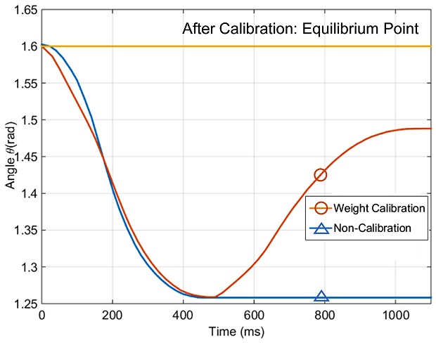
Fig. 19Comparison of angle trajectory following with the impedance control and weight calibration (1 kg weight)

실험결과의 파란색 그래프는 임피던스 제어만 시행했을 때의 결과를 나타낸다. 주황색 그래프는 기구가 무게를 보정하여 무게 보정 알고리즘을 적용하는 과정의 개형을 나타낸다. 노란색 그래프는 보정 후의 목표 평형점 (θeq)에서 무게 보정 알고리즘을 적용한 결과를 나타낸다.
임피던스 제어만 적용한 경우(파란 선), 설정한 평형점과 실제 평형점 간의 오차가 존재한다. 반면, 추가적인 무게로 인한 효과를 보정한 후 무게 보정 알고리즘을 적용한 결과(노란 선)에는 설정한 평형점과 실제 평형점 간의 오차가 없음을 확인할 수 있다.
다만, 정지 마찰력과 기어 백래쉬, 모터 동역학 등의 팔 기능 지지대 모델로 나타내지 않은 요인들로 인해 기구가 최종적으로 도달하는 평형점은 범위로 나타나게 되며 사용자가 목표로 하는 평형점 (
θeq)은 이 범위 안에 나타나게 된다 (
Table 4). 이 결과는 무게 보정 알고리즘을 적용하고 있는 상태에서 목표 평형점 근처에서 각속도가 0인 지점의 범위를 실험적으로 측정하였다.
Fig. 20Actuation of the parallel elastic arm support
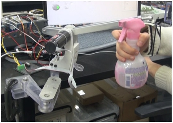
Table 4Range of equilibrium points
Table 4
|
Weight |
500 g |
1 kg |
|
Minimum |
1.47 rad |
1.41 rad |
|
Maximum |
1.73 rad |
1.70 rad |
이러한 실험 결과들은 무게 보정 알고리즘이 기존 방식에 비해 개선된 결과를 나타내며 효과적으로 사용자가 다양한 물체를 집고도 목표 위치로 이동하는 기능을 효과적으로 수행할 수 있음을 의미한다.
5. Conclusions
팔 기능 지지대의 사용성 향상을 위해 기존의 기구를 보완할 수 있도록 스프링과 모터를 함께 사용하는 평행 탄성 구조의 기구를 설계하였다. 기존의 기구와 비교하여 본 팔 기능 지지대는 모터와 스프링을 동시에 이용하며 임피던스 제어를 통해 유연한 거동을 보인다. 또한 기구의 가상 강성과 가상 감쇠 계수를 변경할 수 있고 팔의 중력 보상과 움직임 보조가 가능하다.
평행 탄성 구조와 임피던스 제어를 통한 유연함으로 기구 사용 중에 팔이 벽이나 물체에 부딪히더라도 외부로부터의 충격에도 사용자를 보호할 수 있다. 더불어 스프링이 위치에너지를 저장하여 움직임을 위한 모터 필요 출력이 감소함으로써 모터로만 구동하는 능동형 팔 기능 지지대들보다 필요한 모터의 사양을 낮출 수 있어 전체적인 무게를 줄일 수 있다.
팔 기능 지지대 제어를 통해 사용자가 평형점을 원하는 각도로 설정하면 기구가 원하는 평형점으로 도달하여 근력이 적거나 없는 환자도 높이 방향의 팔 움직임이 가능하다. 추가적인 무게를 보정하는 알고리즘으로 사용자가 숟가락, 물병 등 다양한 종류의 물체를 집더라도 원하는 지점으로 기구가 이동 가능하다. 이러한 기능을 통해 사용자는 팔 기능 지지대를 책상이나 휠체어에 설치하여 몸무게가 다른 다양한 사람들이 사용할 수 있다.
차후 연구를 통해 현재의 원하는 지점을 프로그래밍 상에 입력하는 방식이 아닌 사용자의 의도 인식을 통해 평형점을 실시간으로 변화시켜 음식물 섭취, 세안 및 양치 등의 일상생활동작을 원활히 수행할 수 있게끔 개선하고자 한다.
ACKNOWLEDGMENTS
본 연구는 미공군 Asian Office of Aerospace Research and Development (AOARD, Grand No. FA2386-13-1-4019)의 지원으로 수행되었음.
REFERENCES
- 1.
Van Der Heide, L. A., Gelderblom, G. J., and De Witte, L. P., “Dynamic Arm Supports: Overview and Categorization of Dynamic Arm Supports for People with Decreased Arm Function,” Proc. of the International Conference on Rehabilitation Robotics, pp. 1-6, 2013.
10.1109/ICORR.2013.6650491
- 2.
Atkins, M. S., Baumgarten, J. M., Yasuda, Y. L., Adkins, R., Waters, R. L., et al., “Mobile Arm Supports: Evidence-Based Benefits and Criteria for Use,” The Journal of Spinal Cord Medicine, Vol. 31, No. 4, pp. 388-393, 2008.
10.1080/10790268.2008.11760741
- 3.
Kim, S. H., Byun, Y. C., Son, C. K., Lee, Y. H., and Lee, M. K., “2011 Research on the Actual Condition of the Disabled,” Ministry of Health and Welfare and Korea Institute for Health and Social Affairs, p. 60, 2011.
- 4.
Microgravity Products, “Armon Products Arm Supports Overview,” http://www.armonproducts.nl/armon-ayura.html (Accessed 23 January 2017)
- 5.
Kramer, G., Römer, G. R., and Stuyt, H. J., “Design of a Dynamic Arm Support (DAS) for Gravity Compensation,” Proc. of the International Conference on Rehabilitation Robotics, pp. 1042-1048, 2007.
10.1109/ICORR.2007.4428552
- 6.
Van Ham, R., Sugar, T. G., Vanderborght, B., Hollander, K. W., and Lefeber, D., “Compliant Actuator Designs,” IEEE Robotics and Automation Magazine, Vol. 16, No. 3, pp. 81-94, 2009.
10.1109/MRA.2009.933629
- 7.
Grimmer, M., Eslamy, M., Gliech, S., and Seyfarth, A., “A Comparsion of Parallel and Series Elastic Elements in an Actuator for Mimicking Human Ankle Joint in Walking and Running,” Proc. of the International Conference on Robotics and Automation, pp. 2463-2470, 2012.
10.1109/ICRA.2012.6224967
- 8.
Vanderborght, B., Albu-Schäffer, A., Bicchi, A., Burdet, E., Caldwell, D. G., et al., “Variable Impedance Actuators: A Review,” Robotics and Autonomous Systems, Vol. 61, No. 12, pp. 1601-1614, 2013.
10.1016/j.robot.2013.06.009
- 9.
Sugar, T. G., “A Novel Selective Compliant Actuator,” Mechatronics, Vol. 12, No. 9, pp. 1157-1171, 2002.
10.1016/S0957-4158(02)00021-1
- 10.
Lee, J., Kim, J., and Song, W. K., “User’s Requirements of the Assistive System for the Disabled and Elderly,” Proc. of the Human Computer Interaction of Korea Conference, pp. 334-336, 2011.
- 11.
Microgravity Products, “User Manual Armon Edero,” http://products2.armonportal.com/products/edero/ (Accessed 23 January 2017)
- 12.
Hogan, N., “Impedance Control: An Approach to Manipulation,” Proc. of the American Control Conference, pp. 304, 313, 1984.
10.23919/ACC.1984.4788393
- 13.
Khan, A. M., Ji, Y. H., Ali, M., A., Han, J. S., and Han, C. S., “Passivity Based Adaptive Control and Its Optimization for Upper Limb Assist Exoskeleton Robot,” J. Korean Soc. Precis. Eng., Vol. 32, No. 10, pp. 857-863, 2015.
10.7736/KSPE.2015.32.10.857