ABSTRACT
In this study, slip phenomenon that occurs during trajectory tracking motion of an omni-directional mobile robot based on Mecanum wheels was analyzed. Mecanum wheels which generate the omni-directionality to the mobile robot comprise a centered rim wheel and passive sub-rollers. In forward and backward motion, they function like usual wheels to enable rolling along the ground. However, in sideways motion, they create lateral motion of the mobile robot from the rotational actuation using their peculiar structural configuration, during which slip of the sub-rollers occurs. Unnecessary over-slip of the sub-rollers causes tracking errors of the mobile robot motion. To analyze the properties and reasons for the slip phenomenon, squared and circular trajectory tacking experiments were performed. From the experiments, it was observed that sideways motion generated respectively larger tracking errors than forward and backward motion. The geometric analysis regarding the tracking error generation was discussed using the Mecanum wheel structure. Finally, it was confirmed that suspension mechanism to provide four Mecanum wheels of the mobile robot with even reaction forces on the ground is necessary.
-
KEYWORDS: Mecanum wheel, Omni-directional mobile robot, Slip phenomenon, Suspension, Error improvement
-
KEYWORDS: 메카넘휠, 전방향 이동로봇, 슬립 현상, 서스펜션, 오차 개선
1. 서론
전방향 이동로봇은 로봇 자체의 방향 전환 없이 바퀴의 구조적인 특성에 의하여 전방향으로 이동이 가능한 이동로봇이다. 회전과 이동을 반복적으로 수행하는 일반적인 차량 형태의 이동로봇의 경우 복잡한 경로 생성과 이동 전략이 필요한 반면, 전방향 이동로봇은 방향 전환과 이동이 동시에 이루어질 수 있기 때문에 좁은 공간에서도 간단한 제어로 회전 및 이동을 하면서 원하는 위치까지 도달할 수 있다. 이러한 전방향 이동 방식은 다양한 산업 현장에서 사용되고 있으며, 작업을 위한 추가적인 공간을 전혀 만들어낼 필요 없이 원하는 작업을 수행하거나 원하는 작업 위치까지 이동이 가능하다. 이러한 전방향 이동 방식은 일반 바퀴와는 다른 구조를 가지고 있는 메카넘휠(Mecanum Wheel)에 의해 구현이 가능하다.
하지만 메카넘휠의 바퀴 특성상 전방향성 이동 구현 과정에서 불필요한 슬립(Slip) 현상이 발생하는데, 이러한 슬립이 불균등하게 발생할 경우 목표 경로를 이탈하는 경우가 발생하며, 이는 로봇의 제어에 직접적인 영향을 끼친다. 슬립은 대표적인 비시스템적(Non-Systematic) 요인으로서, 슬립을 발생시키는 요인을 찾아 최대한 줄여주는 것이 필요하다.
본 연구에서는 이동로봇 구동 시 목표 경로를 추종할 수 있도록 슬립 발생에 영향을 주는 요인을 확인하여 줄이고자 하는 해결책을 제시한다. 이동로봇이 다양한 환경에서 목표 경로를 정확히 추종할 수 있도록 불균등한 슬립 발생을 줄이는 것이 필수적이며, 이 연구에서는 슬립 현상 유발과 관련된 실험을 통하여 슬립의 경향을 파악하고 메카넘휠의 구조적 특성과 연계하여 고찰하고자 한다.
2. 전방향 이동로봇 구조
2.1 메카넘휠 기반의 이동로봇 구조
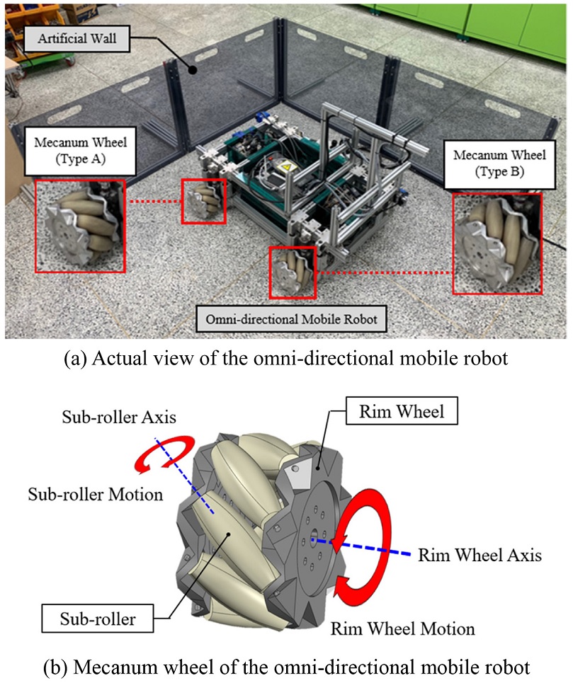
본 연구에 사용된 전방향 이동로봇의 모습을
Fig. 1(a)에서 확인할 수 있다. 이동로봇에 전방향 이동성을 부여하는 메카넘휠은
Fig. 1(b)와 같이 능동적 구동력이 가해지는 림 휠(Rim Wheel)과 수동적으로 단순 회전하는 서브 롤러(Sub-Roller)로 구성되어 있으며, 서브 롤러가 림 휠에 부착된 각도에 따라 A 유형(Type A)과 B 유형(Type B)으로 나누어진다.
1-3 이 두 가지 종류의 휠이 회전하며 발생하는 힘의 합력을 이용하여 로봇의 전방향성이 획득된다.
4
Fig. 1Omni-directional mobile robot based on the Mecanum wheel
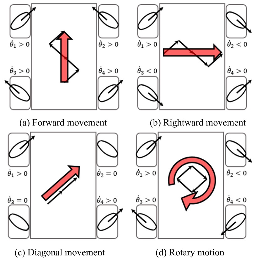
2.2 이동로봇의 전방향 이동 메커니즘
Fig. 2는 이동로봇의 이동 방향을 결정하는 메카넘휠의 구성 및 회전 방향을 나타낸다. 이동로봇 전진 시, 4개의 림 휠에 전진 방향으로 구동력이 가해지면 메카넘휠의 서브 롤러에
Fig. 2(a)와 같이 지면으로부터의 반력이 발생하고, 각 서브 롤러에 가해진 힘의 합력은 전진하는 방향이기 때문에 이동로봇이 앞쪽으로 이동할 수 있게 된다. 이때 이동로봇은 메카넘휠의 림휠의 구르는 방향과 같은 방향으로 이동하고 바퀴에는 구름 현상만 발생하여 일반적인 이동 수단의 바퀴와 동일하게 작동하게 된다. 그러나 이동로봇이 우측으로 이동할 경우, 메카넘휠의 서브 롤러에
Fig. 2(b)와 같이 지면으로부터의 반력이 가해지고, 각 서브 롤러에 가해지는 힘의 합력은 우측으로 이동하는 방향으로 작용하기 때문에 이동로봇이 우측으로 이동하게 된다. 이때 이동로봇은 메카넘휠의 림 휠이 구르는 방향의 수직 방향으로 이동하고 림 휠의 구름이 서브 롤러의 회전과 슬립 현상을 이용하여 우측 방향 속도 성분으로 변환된다. 이동로봇이 대각선 방향으로 이동하거나 회전을 하는 경우,
Figs. 2(c)와
2(d)와 같이 메카넘휠에 반력이 가해지고 각 힘의 합력은 이동로봇을 대각선으로 이동시키거나 회전할 수 있는 방향으로 작용하게된다. 이러한 특성으로, 전방향 이동로봇은 회전 시 일반적인 이동 수단과 같이 일정 공간을 확보하지 않고도 좌우 이동이 가능하며, 좁은 공간에서도 원하는 방향으로 이동할 수 있다는 장점이 있다.
5
Fig. 2Omni-directional mobility
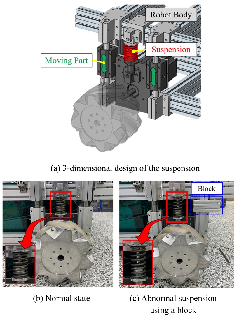
2.3 지면과의 균등한 접지를 위한 서스펜션 구조
전방향 이동로봇의 안정적인 이동을 위해 네 개의 바퀴에 동일한 분력을 전달하는 서스펜션 구조를
Fig. 3(a)와 같이 설치하였다. 로봇의 몸체(Robot Body)와 바퀴 고정부 사이에 연직 방향 상대 운동이 가능하도록 선형 이동 구조(Moving Part)를 설계하고 압축 스프링을 삽입하였다. 이동로봇 구동 시 각 바퀴에 힘이 고르게 분산되도록 작용하여 어느 한쪽으로 반력이 쏠리지 않고 설정한 경로를 따라 전방향으로 이동할 수 있도록 하는 역할을 한다. 본 연구에서는 서스펜션의 필요성에 대한 실험을 진행하기 위해
Fig. 3(b)와 같이 로봇의 몸체와 이동 부분 사이를 강제로 고정하였다. 이를 통해 서스펜션의 기능을 제거함으로써 서스펜션 기능 유무에 따른 이동로봇의 이동 양상을 파악하려고 한다.
Fig. 3Suspension structure of the mobile robot

3. 전방향 이동로봇 시스템 구성 및 제어
3.1 전방향 이동로봇의 시스템 구성
Fig. 4는 본 연구에서 다루는 전방향 이동로봇 시스템의 구성을 보여준다. 이동로봇상에 설치된 공유기(ipTIME N104R)를 통해 이동로봇 전용 와이파이 신호를 생성하며, 노트북과 와이파이를 이용하여 통신하게 된다. 이동로봇 제어기(cRIO-9082)에 장착된 모듈(NI 9205)을 통해 네 바퀴를 독립적으로 구동하여 이동로봇의 이동 방향 및 속도, 위치 등을 제어할 수 있다. 또한 이동로봇에 부착된 초음파센서(PID616110)를 이용하여 이동로봇의 경로 및 위치를 측정할 수 있으며, 수집된 데이터들은 와이파이 신호를 이용하여 노트북 내의 모니터링 프로그램으로 전달된다. 제어기로부터 계산된 명령 신호는 네 바퀴의 모터 드라이버(Yaskawa Servo Pack)를 통해 모터(SGMGV-09A3A21)로 전달된다. 전방향 이동로봇 전체 시스템에 사용된 소프트웨어 및 하드웨어는
Table 1과 같다.
Fig. 4System configuration of the omni-directional mobile robot
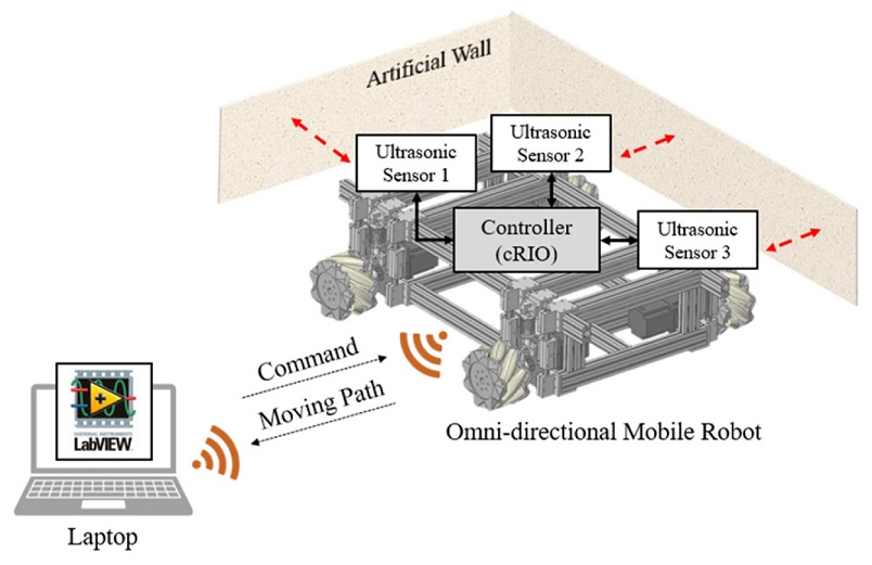
Table 1Specification of the components in the omni-directional mobile robot
Table 1
|
- |
Component |
Model |
Specification |
|
H/W |
Controller |
cRIO-9082 |
Slot : 8
CPU : Intel Core
i7-660UE |
|
Wifi module |
ipTIME N104R |
Speed : 150 Mbps |
|
Analog input |
NI 9205 |
AI : 16 |
|
Ultrasonic sensor |
PID616110 |
AO range : 0-5V
Measuring distance : 15 cm - 5 m |
|
Motion I/O |
NI 9512 |
DI : 4
DO : 2 |
|
Motor driver |
Yaskawa servo pack |
Max motor capacity : 1.0 kW
Output current : 7.6 Arms |
|
BLDC motor |
SGMGV-09A3A21 |
Rated output : 850W
Resolution : 1000000 |
|
S/W |
Control OS |
LabVIEW Softmotion |
2015 FPGA
Module
Motion Control |
|
Graphic analysis |
MATLAB |
2017a MATLAB
Data analysis |
3.2 초음파센서를 이용한 위치 정보 수집
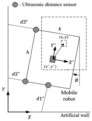
이동로봇이 이동하게 되면 이동로봇에 설치된 초음파센서를 이용하여 이동로봇의 이동 경로를 측정한다.
6,7 초음파센서는 이동로봇의 왼쪽 두 모서리 끝 쪽에 두 개, 하단 중앙부 쪽에 한 개가 설치되어 있다. 이동로봇의 주변에는 인위적으로 설치한 인공 벽이 있으며,
Fig. 5와 같이 벽으로부터 이동로봇까지의 거리를 초음파센서를 이용하여 측정할 수 있다. 측정한 벽과의 거리와 이동로봇의 폭과 길이 정보를 기반으로 한
식(1)을 이용하면 이동로봇의 비틀림 각도
ϕ를 계산할 수 있으며, 비틀림 각도와 초음파센서 측정값을
식(2)에 대입하여 이동로봇의 중심 위치(
x*,
y*)를 계산한다.
d1*,
d2*,
d3*는 3개의 초음파센서에서 벽까지 측정한 거리를 나타내며,
h는 이동로봇 차체의 길이 1100mm를,
k는 이동로봇의 너비 630 mm를 나타낸다. 중심 위치의 좌표는 이동로봇이 이동하는 동안 수집되며, 수집된 좌표의 변화는 MATLAB을 이용하여 도시하고 목표 좌표와 비교하였다.
Fig. 5Schematic diagram for calculation of center coordinates and direction of the mobile robot
3.3 전방향 이동로봇 모션 제어
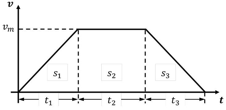
이동로봇이 원하는 경로로 이동하게 하기 위해서는 경로를 따라 이동할 수 있도록 해당 경로에 따른 바퀴 모터의 지령 값을 계산해주어야 한다. 이 지령 값은 바퀴의 속도에 대응되는데, 속도 프로파일은
Fig. 6과 같이 표현된다.
8,9 경로 이동 시 사용자가 설정한 일정 시간 동안 가속 운동, 등속도 운동, 감속 운동을 하며 해당 방향의 이동 속도가 0에 도달하면 다른 방향으로 이동할 수 있게 된다. 이를
식(3)으로 표현할 수 있으며, 가속 운동 시 이동거리를
s1, 등속도 운동 시 이동거리를
s2, 감속 운동 시 이동거리를
s2라 할 때 전체이동 거리를
S로 표현할 수 있다. 이러한 알고리즘을 LabVIEW 내 경로 생성 기능을 수행하는 소프트모션(Softmotion)에 적용함으로써 이동로봇이 이동할 수 있는 직선 경로, 사각형 경로, 원 경로가 만들어진다.
Fig. 6Velocity profile of the mobile robot movement

경로를 따라 구동되는 이동로봇의 선속도는 메카넘휠의 각속도로부터 계산된다. x방향 선속도는
νx, y방향 선속도는
νy로 나타내며, 이동로봇이 회전하는
ϕ 방향에 대한 각속도는
wz로 나타낸다. 이동로봇의 각 메카넘휠의 각속도는
Fig. 2에서와 같이
θ˙ii=1,2,3,4로 표현되며
식(4)의 순 속도 기구학에 의해 이동로봇의 선속도가 계산된다. 이때
R은 메카넘휠의 외경이며
l1 과
l2는 각각 이동로봇의 차체의 길이와 너비의 절반인
h/2와
k/2를 의미한다.
식(5)는 메카넘휠의 각속도와 이동로봇의 선속도 사이의 역속도 기구학을 나타낸다.
4. 전방향 이동로봇 성능 평가 실험
4.1 전방향 이동로봇의 경로 생성
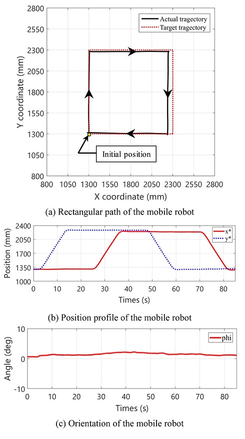
이동로봇의 기본적인 성능을 평가하기 위해 전후진 이동과 좌우 이동이 모두 포함된 사각형 경로 및 원 경로 이동 실험을 진행하였다. 경로 진행 방향은 시계방향으로 이루어지고 사각형 경로 이동 시 한 변의 경로를 이동할 때마다, 원 경로 이동 시 원 전체의 경로를 이동할 때마다
Fig. 6의 속도 프로파일 생성 과정을 거치게 된다. 사각형 경로 이동 시 사각형의 꼭짓점 부분에 도달하여 이동 방향을 바꿔야 할 때 이동로봇의 속도는 0이 된다. 이러한 과정을 네 번 거친 후 출발점으로 돌아온 이동로봇의 이동 양상을
Fig. 7(a)에서 확인할 수 있다.
Fig. 7Position and orientation of the mobile robot following

그래프상 이동 경로는 이동로봇의 중심이 이동하는 경로를 나타낸 것이며, 이동로봇의 중심 좌표를
x*,
y*로 표현하였다.
Fig. 7(b)에 사각형 경로 이동 시 이동로봇 중심 좌표
x*,
y*의 변화를 나타내었으며,
Fig. 7(c)에 사각형 경로 이동 시 이동로봇 비틀림 각도의 변화를 나타내었다. 원 경로의 경우 항상 이동 방향이 바뀌어 여러 번의 속도 프로파일 과정이 불가능하므로 이동로봇이 출발하여 출발점으로 다시 돌아올 때까지 속도 프로파일 과정을 한 번 거치게 된다. 이동로봇의 목표 경로와 실제 경로 중 네 점의 위치를
Table 2에 나타내었다. 이동로봇의 원 경로 이동 양상은
Fig. 8(a)에서 확인 가능하다. 사각형 경로 이동과 마찬가지로, 이동로봇의 중심 좌표가 이동하는 경로를 나타낸 것이며,
Fig. 8(b)에서 중심 좌표
x*,
y*의 변화를 확인할 수 있다.
Fig. 8(c)에서는 원 경로 이동 시 이동로봇 비틀림 각도의 변화를 확인할 수 있다. 이동로봇의 목표 경로와 실제 경로 중 네 점의 위치를
Table 3에 나타내었다.
Figs. 7(a)와
8(a) 모두 이동로봇이 목표 경로를 대체로 따라가는 양상을 보이지만 지면과의 슬립 등의 영향으로 목표 경로를 정확하게 추종하지는 못하는 것을 확인할 수 있다.
Table 2Corner coordinate of the mobile robot trajectory
Table 2
|
|
1st |
2nd |
3rd |
4th |
|
Target trajectory |
x |
1300.032 |
1305.997 |
2247.015 |
2236.627 |
|
y |
1300.562 |
2280.986 |
2280.019 |
1291.981 |
|
Actual trajectory |
x |
1300 |
1300 |
2300 |
2300 |
|
y |
1300 |
2300 |
2300 |
1300 |
Fig. 8Position and orientation of the mobile robot following the circular path
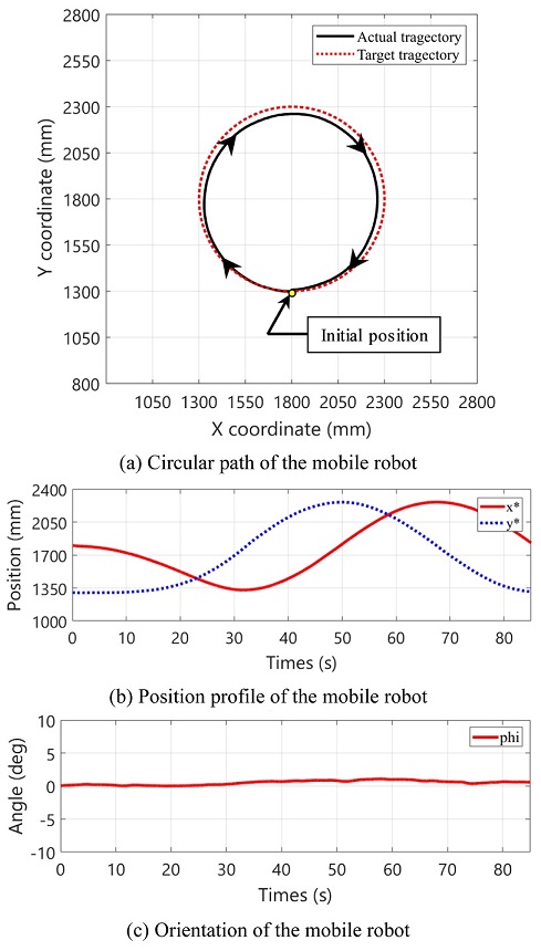
Table 3Corner coordinate of the mobile robot trajectory
Table 3
|
|
1st |
2nd |
3rd |
4th |
|
Target trajectory |
x |
1800.942 |
1328.71 |
1800.03 |
1800.028 |
|
y |
1300.303 |
1800.671 |
2261.15 |
2261.524 |
|
Actual trajectory |
x |
1800 |
1300 |
1800 |
2300 |
|
y |
1300 |
1800 |
2300 |
1800 |
사각형과 원 경로 이동 시 실제 이동 경로와 목표 경로와의 차이를 비교했을 때, 좌우 경로 차이가 앞뒤 경로 차이보다 더 발생하였다는 것을 확인하였다. 이 현상의 원인 파악을 위해 이동로봇의 전후진 이동과 좌우 이동의 차이를 분석하였다. 이동로봇이 앞쪽 방향으로 이동할 경우 구름 현상을 이용한 바퀴의 구동은 비교적 슬립이 적어 이동로봇을 목표 위치까지 이동할 수 있게 한다. 반면 이동로봇이 좌우 방향으로 이동할 경우 림 휠의 구름 현상보다는 서브 롤러의 슬립 현상의 영향을 많이 받게 된다. 이때 불필요한 슬립이 추가로 경향을 파악하기 위하여, 서스펜션 기능을 변화시켜가며 추가적인 실험을 진행하였다.
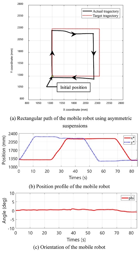
4.2 전방향 이동로봇 서스펜션 기능 평가 실험
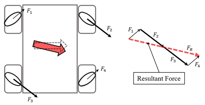
이동로봇의 서스펜션 기능을 제거해 서스펜션이 끼치는 영향을 파악하는 실험을 구성하였다. 이동로봇의 왼쪽 후방 바퀴와 오른쪽 전방 바퀴의 서스펜션의 기능을 발휘하지 못하도록 스프링 부분을 강제로 고정하여 서스펜션의 기능을 억제하고 비대칭 상황을 유발하였다. 서스펜션의 기능을 조절함으로써 특정 바퀴에 힘이 더 많이 가해지게 되고, 결과적으로 목표 경로를 이탈하여 이동하게 된다. 서스펜션의 기능을 조절한 바퀴에는
Fig. 11의
F2 및
F3과 같이 상대적으로 큰 지면 반력이 작용하게 된다. 따라서 우측 방향으로 이동 중 이동로봇의 뒤쪽 방향으로 결과력(Resultant Force)이 생성되어 온전히 우측 방향이 아닌 대각선 방향으로 힘이 가해진다.
Fig. 9(a)에서 사각형 경로 이동 시 측면으로 이동 중 이와 같은 양상으로 경로를 이탈하는 것을 확인할 수 있다. 사각형 경로를 이탈한 이동로봇의 중심 좌표인
x*,
y*의 변화를
Fig. 9(b)에, 비틀림 각도의 변화를
Fig. 9(c)에 나타내었으며,
Fig. 7(a)에 비해 매끄럽지 않은 그래프의 모습을 통해 사각형 경로를 이탈하였다는 것을 확인할 수 있다.
Fig. 10(a)에서 원 경로 이동 시 경로를 이탈한 양상을 확인할 수 있다. 이때 측정한 이동로봇의 중심 좌표
x*,
y* 또한
Fig. 10(b)에서 확인할 수 있으며,
Fig. 9(b)와 비교하였을 때 경로 이탈로 인해 상당량 변형되었음을 확인할 수 있다. 비틀림 각도의 변화를 나타내는
Fig. 10(c) 그래프에서는 정상적인 각도인 0도에 못 미침으로써 원 경로 이동 시 여러 차례의 비틀림이 발생하였다는 것을 알 수 있다. 이동로봇의 목표 사각형, 원 경로와 서스펜션 기능을 제거한 이동로봇의 실제 사각형, 원 경로 중 네 점의 위치를
Tables 4와
5에 나타내었다.
Fig. 9Position and orientation of the mobile robot following the rectangular path

Fig. 10Position and orientation of the mobile robot following the circular path
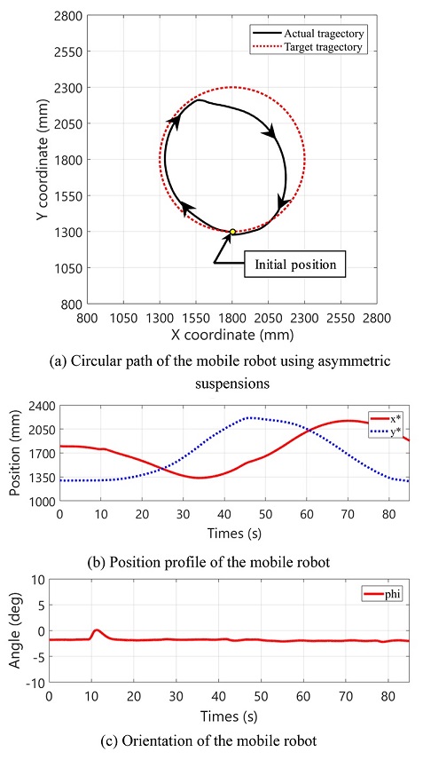
Fig. 11The geometric analysis about uneven reaction forces on the ground

Table 4Corner coordinate of the mobile robot trajectory
Table 4
|
|
1st |
2nd |
3rd |
4th |
|
Target trajectory |
x |
1300.167 |
1363.414 |
2175.139 |
2183.634 |
|
y |
1300.002 |
2262.238 |
2197.053 |
1231.304 |
|
Actual trajectory |
x |
1300 |
1300 |
2300 |
2300 |
|
y |
1300 |
2300 |
2300 |
1300 |
Table 5Corner coordinate of the mobile robot trajectory
Table 5
|
|
1st |
2nd |
3rd |
4th |
|
Target trajectory |
x |
1800.306 |
1335.804 |
1800.409 |
2155.685 |
|
y |
1300.019 |
1800.518 |
2156.95 |
1800.331 |
|
Actual trajectory |
x |
1800 |
1300 |
1800 |
2300 |
|
y |
1300 |
1800 |
2300 |
1800 |
5. 결론
이 연구에서는 메카넘휠에 기반을 둔 전방향 이동로봇의 슬립 현상 및 원인이 소개되고 이를 실험적으로 검증하는 작업이 수행되었다. 이동로봇의 좌우 이동 시 목표 경로를 추종하지 못하는 현상을 확인하는 실험이 수행되었고 이러한 현상은 메카넘휠에서 불필요하게 추가적으로 발생하는 슬립을 통해 발생하는 것을 확인하였다. 이러한 슬립은 이동로봇의 경로 이탈을 유발하므로 전방향 이동로봇을 다양한 환경에서 원하는 경로를 따라 구동하기 위해서는 메카넘휠에서 발생하는 슬립을 줄여 경로 이탈을 최소화하는 것이 요구된다. 슬립 현상의 최소화를 위해 이동로봇의 각 바퀴에 균일한 분력이 분산되도록 하는 서스펜션의 기능이 요구되며, 목표 경로를 보다 근접하게 추종하기 위해서는 전방향 이동로봇에 서스펜션뿐만 아니라 부가적인 외부 센서가 필요할 것으로 판단된다.
ACKNOWLEDGMENTS
본 연구는 국토교통부 국토교통기술촉진연구사업의 연구비지원(19CTAP-C153093-01-000000)에 의해 수행되었습니다.
REFERENCES
- 1.
Jeong, J., Kwon, S. J., Chu, B., and Park, J., “Unified-Type Design and Structural Analysis for Mecanum Wheel Performance Improvement,” Journal of the Korean Society of Manufacturing Process Engineers, Vol. 13, No. 2, pp. 117-123, 2014.
10.14775/ksmpe.2014.13.2.117
- 2.
Shin, S. J., Kim, H., Kim, S. H., and Chu, C. N., “A New Wheel Arrangement by Dynamic Modeling and Driving Performance Analysis of Omni-Directional Robot,” Journal of the Korean Society for Precision Engineering, Vol. 30, No. 1, pp. 18-23, 2013.
10.7736/KSPE.2013.30.1.18
- 3.
Chu, B. and Sung, Y. W., “Development of Educational Robot Platform based on Omni-Directional Mobile Mechanism,” Journal of the Korean Society for Precision Engineering, Vol. 30, No. 11, pp. 1161-1169, 2013.
10.7736/KSPE.2013.30.11.1161
- 4.
Cho, G. and Chu, B., “Performance Evaluation of Concrete Polishing Robot with Omni-Directional Mobile Mechanism,” Journal of the Korean Society of Manufacturing Technology Engineers, Vol. 25, No. 2, pp. 112-117, 2016.
10.7735/ksmte.2016.25.2.112
- 5.
Chu, B. and Sung, Y. W., “Mobile Performance Evaluation of Mecanum Wheeled Omni-Directional Mobile Robot,” Journal of the Korean Society of Manufacturing Technology Engineers, Vol. 23, No. 4, pp. 374-379, 2014.
10.7735/ksmte.2014.23.4.374
- 6.
Chu, B., Cho, G., and Sung, Y. W., “Position Control Algorithm and Experimental Evaluation of an Omni-Directional Mobile Robot,” Journal of the Korean Society of Manufacturing Technology Engineers, Vol. 24, No. 2, pp. 141-147, 2015.
10.7735/ksmte.2015.24.2.141
- 7.
Joung, I. S. and Cho, H. S., “Self-Localization for Mobile Robot Navigation Using an Active Omni-Directional Range Sensor,” Journal of the Korean Society for Precision Engineering, Vol. 16, No. 1, pp. 253-264, 1999.
- 8.
Kim, K. H., Yoon, K. H., and Lee, J. H., “Path Generation Algorithm Development for Ultrafast/Wide Area Laser Processing,” Journal of the Korean Society for Precision Engineering, Vol. 27, No. 10, pp. 34-39, 2010.
- 9.
Lee, J. Y. and Hyun, C. H., “Torque Control of DC Motor Using Velocity Profile based Acceleration/Deceleration Control,” Journal of Korean Institute of Intelligent Systems, Vol. 22, No. 1, pp. 36-41, 2012.
10.5391/JKIIS.2012.22.1.36
Biography
- Seolha Kim
M.S. candidate in the Department of Mechanical System Engineering, Kumoh National Institute of Technology. Her research interest is robotics.
- Cheonghwa Lee
He received the B.S. and M.S. degrees in mechanical system engineering from the Kumoh National Institute of Technology in 2017 and 2019, respectively. He will be working toward the Ph.D. degree in electrical and computer engineering in Seoul National University. He is currently a Research Assistant with the Korea Institute of Industrial Technology. His current research interest focuses on artificial intelligence-based robotic automation control and applications.
- Baeksuk Chu
Associate Professor in the Department of Mechanical System Engineering, Kumoh National Institute of Technology. His research interest includes robotics, mechatronics, intelligent control and reinforcement learning.