ABSTRACT
Among 3D printing techniques, fused deposition modeling (FDM) is known for its design flexibility, rapid fabrication, and the ability to produce complex geometries without molds. However, weak interlayer adhesion often results in poor mechanical strength along the build (Z) direction, limiting its use in structural applications. Instead of altering printing parameters or switching technologies, we propose a simple microwave-irradiation post-treatment to enhance interlayer bonding in FDM-printed parts. By optimizing microwave power and exposure time, we significantly improved interlayer fusion while maintaining the original geometry. Cross-sectional microscopy before and after treatment confirmed markedly improved interlayer bonding (Unbonded interfacial area fraction: 56.82% → 15.51%; -41.31 percentage points, -72.7%). Correspondingly, the Z-direction tensile strength increased from 42.38 to 49.11 MPa (+6.73 MPa, +15.9%). This straightforward post-processing method effectively addresses a key limitation of FDM, thereby expanding its potential for structural and industrial applications.
-
KEYWORDS: 3D printing, Fused deposition modeling, Microwave, Polymer composite
-
KEYWORDS: 3차원 프린팅, 용융 적층 모델링, 마이크로파, 고분자 복합재료
NOMENCLATURE
Glass Transition Temperature
1. 서론
3D 프린팅 기술은 디지털 모델을 기반으로 재료를 적층하여 특정 형상의 물체를 제조하는 기술로, 높은 디자인 자유도, 생산 유연성, 신속한 프로토타이핑(Rapid Prototyping)등의 장점으로 비금형 공정, 비정형 및 자유 형상 제작, 소량 다품종 생산 등에 활용되고 있다[
1,
2]. 최근의 3D 프린팅 기술은 단순한 시제품 제작을 넘어 기능성 부품, 맞춤형 구조체, 의료용 임플란트, 전자소자 내장형 부품 제작 등으로의 응용이 활발히 진행되고 있다[
3,
4]. 또한, 4D 프린팅 기술이나 복합재료 기반의 고기능 구조물 제조분야로의 확장이 이루어지며, 산업용, 구조용, 스마트 소재 중심으로 한 응용분야의 확장이 진행되고 있다[
3,
4].
특히, 3D 프린팅 기술 중 Fused Deposition Modeling (FDM) 방식은 디자인의 자유도, 빠른 제작 속도, 그리고 별도의 금형 없이 복잡한 형상을 구현할 수 있는 장점을 가지고 있어, 러프 프로토타입 제작, 교육, 의료, 디자인 분야 전반에서 폭넓게 활용되고 있다[
5-
8]. 그러나 FDM 공정은 열가소성 재료를 연속적으로 적층하는 제조방식으로 인해 적층 방향(Z-축)의 기계적 강도가 낮고, 층간 접합 불량이 발생한다는 구조적 단점을 갖는다[
9,
10]. 이러한 문제는 실제 구조용 부품으로의 적용에 제한 요소로 작용하며, 제품이 비등방성(Anisotropy) 기계적 물성을 가지도록 하여 실제 산업적 활용에 한계를 지니게 된다.
이러한 한계를 극복하기 위해 지금까지 다양한 접근방법의 연구가 수행되어 왔으며, 대표적으로 1) 프린팅 파라미터(적층 속도, 노즐 온도, 층 두께 등)의 공정 최적화, 또는 2) 새로운 방식의 프린팅 기술(예: SLA, SLS) 적용 등이 있다[
11-
13]. 하지만 기존의 접근 방식은 필라멘트 소재의 변경 혹은 공정 자체의 복잡화가 요구되고, 이에 따른 공정 비용 증가 및 설비 제약 등의 한계를 동반한다. 또한, 열처리를 이용한 대표적인 후처리 공정은 외부에서 내부로 열이 전달되는 전도·대류 방식에 의존하기 때문에, 적층 계면까지 충분히 열을 전달하려면 수십 분 이상의 장시간 가열이 필요하다[
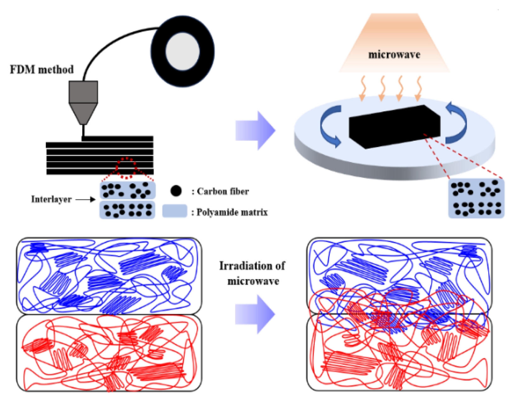
14]. 이로 인해 공정 효율이 낮고, 산업적 확장성에도 제약이 발생한다. 이에 본 연구에서는 소재 개발, 프린팅 공정 및 프린터 구조 개선 없이, 범용 가능한 마이크로웨이브 조사(Microwave Irradiation)를 통해 적층 간 계면(Interlayer Interface)의 접합력을 개선하여 기계적 물성을 제고하고자 하였다. Microwave는 고분자 내에 분산되어 있는 Carbon Fiber를 가열시켜 분자 진동 및 국부적인 유동(Localized Chain Mobility)을 유도할 수 있으며, 이로 인해 적층 계면의 분자 간 확산(Diffusion) 및 재배열(Rearrangement)이 촉진될 수 있다. 단일 고분자 물질에 Microwave를 조사시킬 경우, 쌍극자 회전과 유전손실 메커니즘에 의해 열이 발생하므로 발열 속도가 느리고(200 W에서, 수십 분) 균일한 발열이 발생하지만, 탄소 섬유가 복합화된 고분자 물질에 Microwave를 조사시킬 경우 전도 손실 메커니즘에 의해 열이 발생함으로 발열 속도가 빠르고(200 W에서, 수십 초) 국부적이 가열이 발생한다[
15]. 이러한 메커니즘은 탄소 섬유가 복합화된 FDM 제품의 적층 경계를 융합시켜 계면 접합력을 개선하여 Z-축의 기계적 물성을 향상시킬 수 있다[
16,
17]. 이전에, Microwave 조사를 활용한 고분자 복합소재의 기계적 물성 향상에 대한 많은 연구들이 보고되어 왔다[
18-
21]. 하지만 적층 경계만을 선택적으로 가열하기 위해 CNT (Carbon Nanotube), CF (Carbon Fiber) 등의 전도성 필러를 표면에 코팅하는 추가 공정이 요구되거나, 과도한 조사 출력과 시간으로 기존 3D 형상이 붕괴되는 한계를 보였다[
19,
20]. 이에 본 연구에서는 Microwave의 출력(Watt)과 조사 시간(Irradiation Time)을 변수로 설정하여, 3D 형상의 유지와 면간 접합력 향상 사이의 최적 조건을 도출하였으며, Microwave 조사 전 후의 기계적 물성 증가와 면간 접합의 개선을 확인하였다. 이를 통해 Z-축의 기계적 물성 저하를 막고 산업적 활용의 다양성을 확대하고자 한다.
2. 실험
2.1 재료
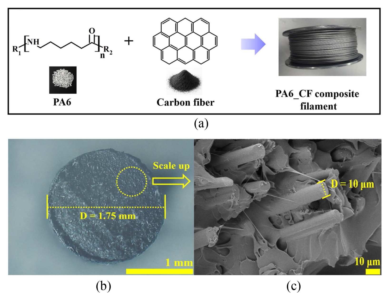
본 연구에서 3D 프린팅 재료로 사용된 Filament 소재는 Markforged사에서 구매하였으며,
Fig. 2(a)과 같이 PA6 (Polyamide6)에 탄소섬유(Carbon Fiber)가 15wt% 함유된 복합소재이다.
Figs. 2(b)와
2(c)는 Filament 단면의 OM (Optical Microscopy) 이미지이다. Filament 직경은 1 .75 mm이며, PA6 고분자 매트릭스에 탄소섬유가 균일하게 분산되어있다.
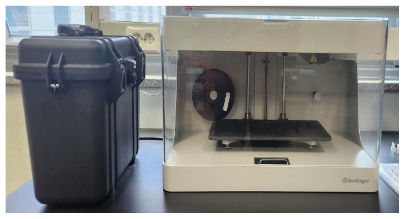
본 연구에서는
Fig. 3 이미지와 같이 Markforged (USA)사의 MarkTwo 모델을 사용하였다. 3D 프린팅 조건은
Table 1에 정리하였고, 인장강도 시편, 굴곡강도 시편 제작을 위한 치수 규격은
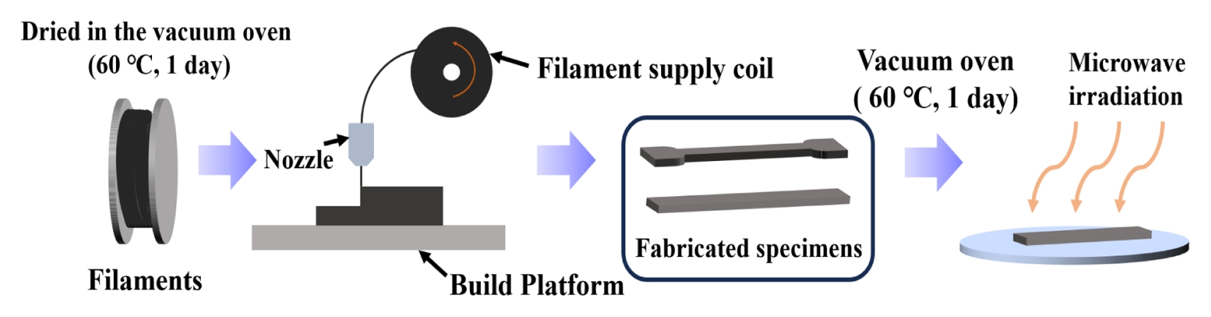
Fig. 4과 동일하다. 3D 프린팅은 FDM 방식을 사용하였고, Filament는 프린팅 전 60°C 진공 조건에서 24시간 건조하였다. FDM 방식으로 제작된 인장강도, 굴곡강도 시편은 Microwave 조사 전 동일한 조건으로 건조하였다. 전체적인 실험 과정은
Fig. 5와 같다.
본 연구에서 Microwave 조사는
Fig. 6(a)와 같이 100 W 단위로 출력 조절이 가능한 Winia (Korea)사의 GKRI3100DSK 모델 Microwave Oven을 사용하여 조사하였다. 조사 파장은 2.45 GHz이며, 조사 출력은 각각 100, 200, 300 W로 진행하였다. 모든 시편은 60
oC 오븐에서 24 시간 동안 진공 건조 후 Microwave 조사를 진행하였다.
2.4.1 표면온도 측정
표면 온도 측정은
Fig. 6(b)와 같이 FLIR(USA)사의 Test Tools A30모델을 사용하여 측정하였다.
2.4.2 열적 특성 분석
Microwave 조사 전 후 녹는점(T
m)과 변위 엔탈피(∆H)는
Fig. 6(c)와 같이 TA사(USA)의 SDT Q600모델 DSC (Differential Scanning Calorimeter)를 사용하여 측정하였으며, 25-300
oC 구간을 10
oC/min의 일정 변위 속도로 분석하였다.
2.4.3 미세 구조 분석
Microwave 조사 전 후의 결정상 및 결정화도 분석은
Fig. 6(d)와 같이 Bruker사(USA)의 ULTIMA4 모델 XRD (X-ray Diffractometer)을 사용하여 측정하였으며, 0-60
o의 스캔 범위와, 1
o/min의 일정 변위 속도로 분석하였다. 적층 구조 변화는
Fig. 6(e)와 같이 JEOL 사(Japan)의 JSM-7600 모델 SEM (Scanning Electron Microscope)를 사용하여 분석하였으며, 전하 축적 방지를 위해 10 mA에서 90초동안 백금 코팅을 진행하였다. 모폴로지 분석은 5-20 kV 가속 전압에서 고진공 모드로 촬영하였다.
2.4.4 기계적 특성 분석
Microwave 조사 전 후의 인장강도와 굴곡강도는
Fig. 6(f)와 같이 Galdabini사(Italy)의 Quasar 50 모델 UTM (Universal Test Machine)을 사용하여 측정하였으며, 5 mm/min의 일정 변위 속도로 진행하였다.
3. 결과
3.1 Microwave 조사 조건 최적화
Microwave 조사 시, 출력이 너무 높거나 장시간 조사된다면 PA6의 녹는점(T
m ≈ 205
oC)에 도달해 3D 형상 붕괴가 발생한다. 반대로 너무 낮은 출력, 혹은 단시간 조사된다면 PA6의 유리전이온도(T
g, 75
oC)에 도달하지 못해 고분자의 국부적인 유동이 불가능하다. 본 연구에서는 인장시편에 Microwave를 조사를 통해 Microwave 출력과 조사 시간을 최적화해 3D 형상을 유지시킴과 동시에 계면 접합 불량을 개선하고자 했다.
Table 2와 같이 Microwave 출력은 100, 200, 300 W에서 각각 진행했으며, 시간에 따른 형상 변화 유무와 표면 온도를 측정하였다.
Fig. 7과 같이 각 조건에 따른 표면온도를 IR (Infrared) Radiation 이미지를 통해 측정하였으며,
Fig. 8은 표면 온도에 따른 형상 이미지이다. 초기 조건에서 Microwave Oven으로 조절 가능한 가장 낮은 출력인 100 W에서 Microwave 조사를 진행하였다. 100 W 출력에서 1,800 초 후 58.6
oC에 도달했고, 2,400 초 후에는 90.5
oC에 도달했으며, 3,000초 후 131
oC에 도달해 형상의 변형을 확인할 수 있었다. 이 결과를 통해 100 W의 출력으로 Microwave 조사 시 온도 상승이 매우 느리게 진행된다는 것과 표면 온도와 내부 온도의 상이한 차이가 존재한다는 것을 확인할 수 있었다. 이후 200과 300 W에서 추가조사를 진행하였다. 200 W 출력에서 40초 후 표면 온도가 102.5
oC에 도달했으며, 50초 후에는 124.8
oC에 도달한 것을 확인했으며, 추가로 60초 조사를 진행하였을 때는 138.6
oC에 도달했다. 200 W 출력에서 60초 조사된 인장시편은 앞선 결과들과는 다르게 소재의 유동성이 커져 3D 형상 변형이 발생한 것을 확인하였다. 이 결과는 출력(W)과 발열은 선형으로 비례하는 것이 아닌, 높은 출력에서는 Microwave의 짧은 조사 시간 차이가 큰 온도 변화를 발생시킬 수 있다는 것을 보여준다. 더욱 높은 출력에 대한 조사 결과를 확인하기 위해 300 W 출력에서 조사를 진행하였다. 그 결과, 300 W 출력에서는 10초이하라는 매우 짧은 조사 시간에도 불구하고 형상이 변형되었으며, 표면 온도 또한 185.5
oC로 매우 높은 온도를 나타냈다.
Fig. 9는 형상 변형이 발생하는 임계 지점을 Microwave 조사 출력과 시간에 대하여 도식화한 그래프이다. 본 연구에서는 조사 시간의 적절한 조절이 가능한 200 W가 가장 적합한 조사 출력이라고 판단하였고, Microwave 조사를 각각 40초, 50초로 각각 진행 후 기계적 특성과 열적 특성 평가를 진행하였다. 또한, 탄소 섬유 배향이 마이크로파 가열 특성에 직접적인 영향을 미친다는 이전 연구를 바탕으로 Flat-build와 Standing-on-build로 제작된 인장 시편에 대해서 Microwave 조사에 따른 영향을 분석하였다[
21]. 탄소섬유가 인쇄 방향과 일정하게 정렬될수록 Microwave가 섬유를 따라 더 효과적으로 전달되어 발열이 집중되기 때문에, 섬유가 동일한 방향으로 모여 있을 경우 국부 발열이 균일하게 발생하여 층간 계면까지 열이 잘 확산되지만, 섬유가 불규칙하게 배열되면 전자기장의 결합이 분산되어 온도 상승이 고르지 못하다.
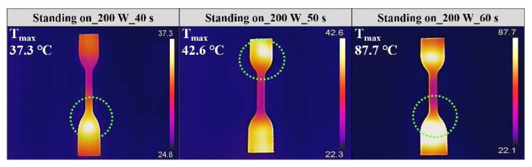
Fig. 10은 Standing-on-build로 제작된 인장시편에 대해 200 W에서 각각 40, 50, 60초 Microwave 조사 후 표면온도를 측정한 IR 이미지이다. Flat-build로 제작된 인장 시편(
Fig. 7)은 200 W에서 60초 조사 시 138.6
oC의 높은 표면 온도로 형상 변형이 발생한 것에 비해 Standing-on-build로 제작된 인장 시편은 87.7
oC의 낮은 표면 온도로, 형상 또한 유지되었다. 본 연구에서는 Microwave 효율성 극대화 및 최적화 방식을 위해 모든 시편을 Flat-build 제작하였다.
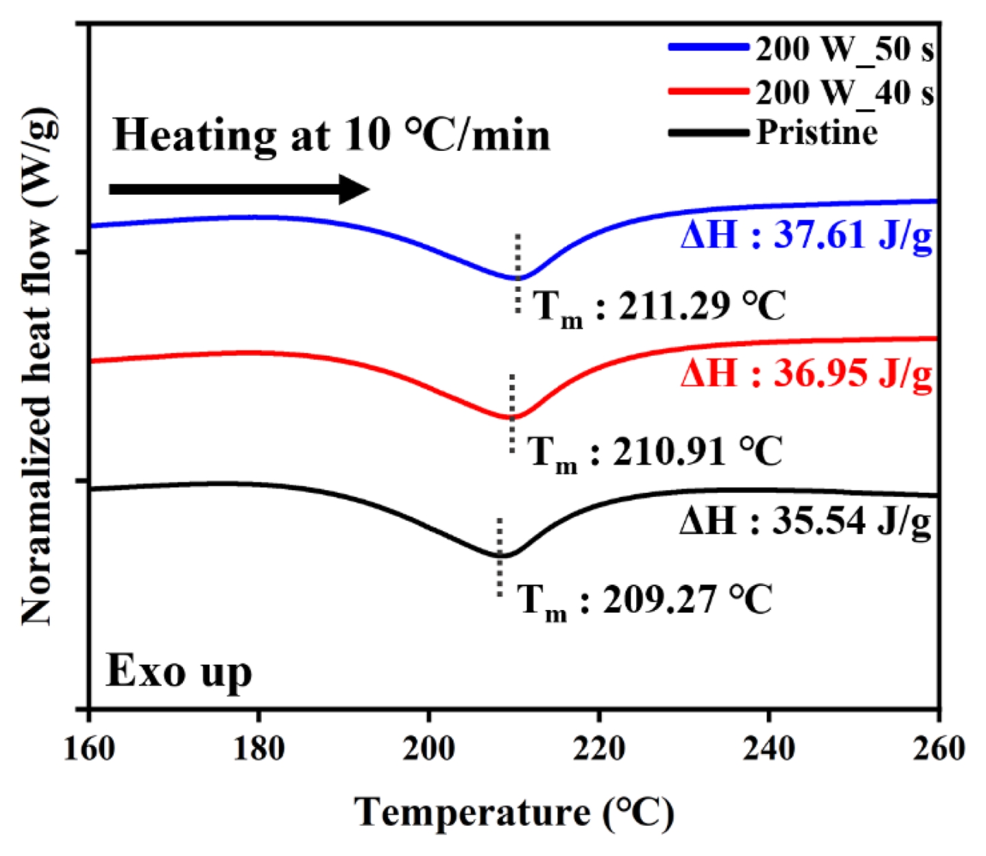
Microwave 조사가 PA6/CF 복합체의 열적 거동에 미치는 영향을 확인하기 위해, DSC 분석을 진행하였다.
Fig. 11은 첫 번째 가열 시 발생하는 에너지 변화를 나타내며, 각 peak에 대한 흡열 엔탈피(W/g) 값을 보여준다. 초기 시편은 녹는점(T
m)이 약 209.27°C에서 나타났으며, Microwave 조사 후 각각 210.91°C (200 W_40 s), 211.29°C (200 W_50 s)로 소폭 상승하였다. 또한,
식 (1)을 사용하여 흡열 엔탈피 값을 통해 결정화도(X
c%)를 분석[
22]했으며, 초기 21.26%에서 Microwave 조사 후 각각 21.99%, 22.39%로 결정화도 또한 소폭 증가한 것을 확인할 수 있었다.
Table 3는 초기 시편과 Microwave 조사 후 녹는점과 결정화도 값을 보여준다. 이 결과는 Microwave 조사를 통해 적층 구간이 개선되는 과정에서 고분자 사슬이 보다 정돈되며, 그 결과 결정화도 및 녹는점이 증가된 것으로 해석된다.
∆Hm = The measured melting enthalpy (W/g) of the sample
∆Hf = The theoretical melting enthalpy of 100% crystalline polymer (197.6 W/g)
wf = Weight fraction of the filler or non-crystalline component
3.3 결정화도 분석
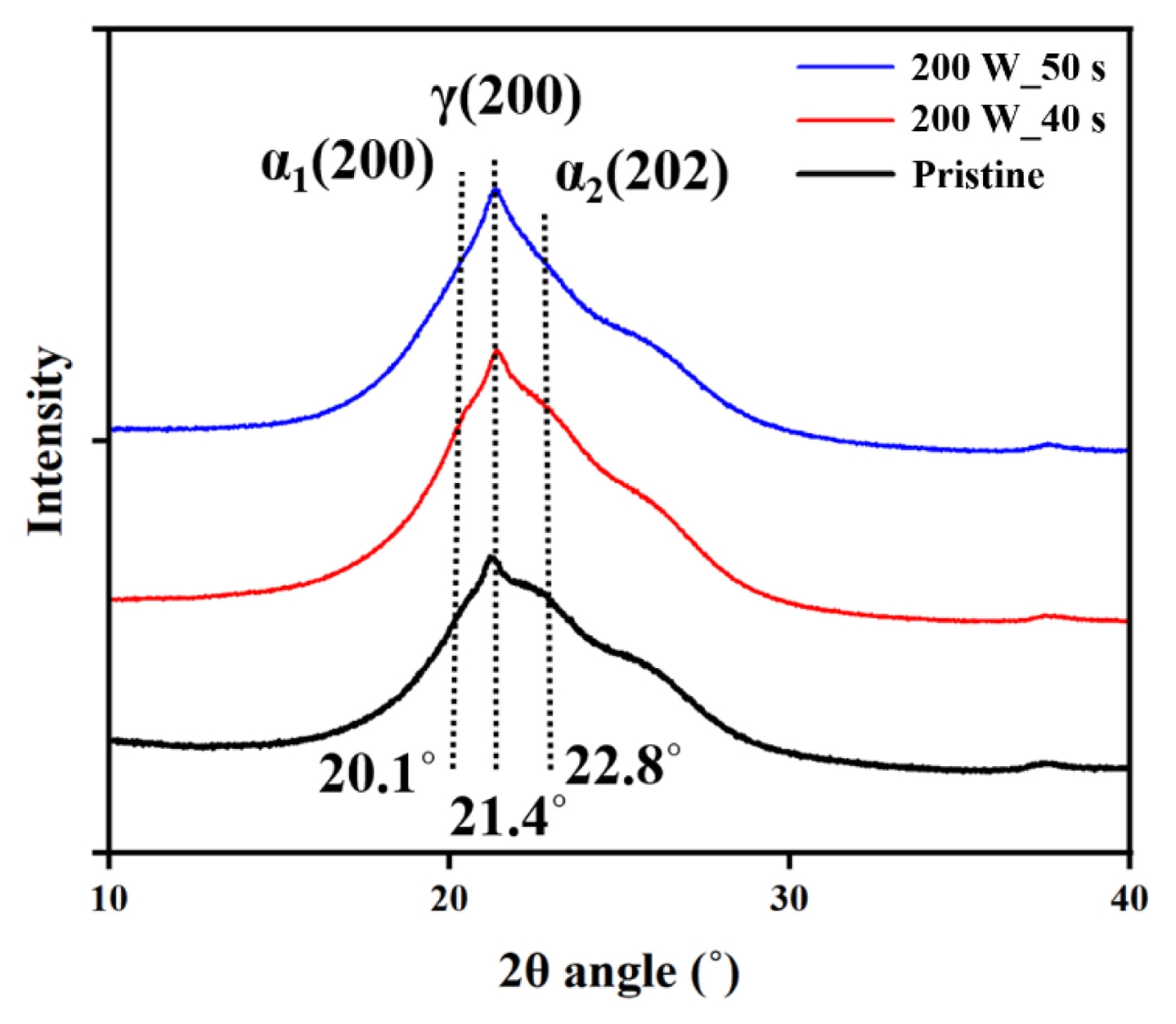
결정화도 변화를 명확히 규명하기 위해 XRD 분석을 추가로 진행하였다. PA6는 일반적으로 100
oC 이상에서 α상(20.1°, 22.8°)과 γ상(21.4°)의 두 가지 결정상을 형성하는데[
21], 각 결정상은 사슬 배열과 밀도, 형성 온도에 차이가 존재한다. PA6의 α상은 사슬간 수소결합에 의해 보다 정렬된 구조를 형성하고 있어 높은 밀도(≈ 1.23 g/cm³)를 가지며, 약 150
oC 이상에서 주로 형성된다. γ상은 α상에 비해 상대적으로 무질서하게 정렬되어 있어 낮은 밀도(<1.20 g/cm
3)를 가지며, 약 105-150
oC 부근에서 생성된다[
23].
Fig. 12은 XRD 그래프이며, 결정상에 대한 Peak 면적 비율은
Table 4과 같다. Microwave 조사를 통해 α
1 및 α
2 peak 강도는 점진적으로 증가한 반면, γ상의 강도는 점진적으로 감소하여 함량의 감소를 확인할 수 있다. 이러한 경향은 Microwave 조사로 인해 고분자 사슬의 유동성이 증가하고, 분자 간 재배열이 일어나면서 상대적으로 무질서한 γ상이 보다 안정한 α상으로 전이되었음을 시사한다. 이와 같은 분자 정렬의 증가는 앞서 DSC 분석(
Table 3)에서 확인된 녹는점의 증가 및 결정화도 상승과도 일치한다. 또한, 복합화된 CF로 인해 결정 성장이 가속화되어 고밀도의 α상 결정 구조 형성을 유도된다[
24]. 이는 FDM 방식으로 제조된 PA6/CF 복합체의 층간 결합력 및 기계적 특성을 효과적으로 개선할 수 있는 방법임을 확인할 수 있다.
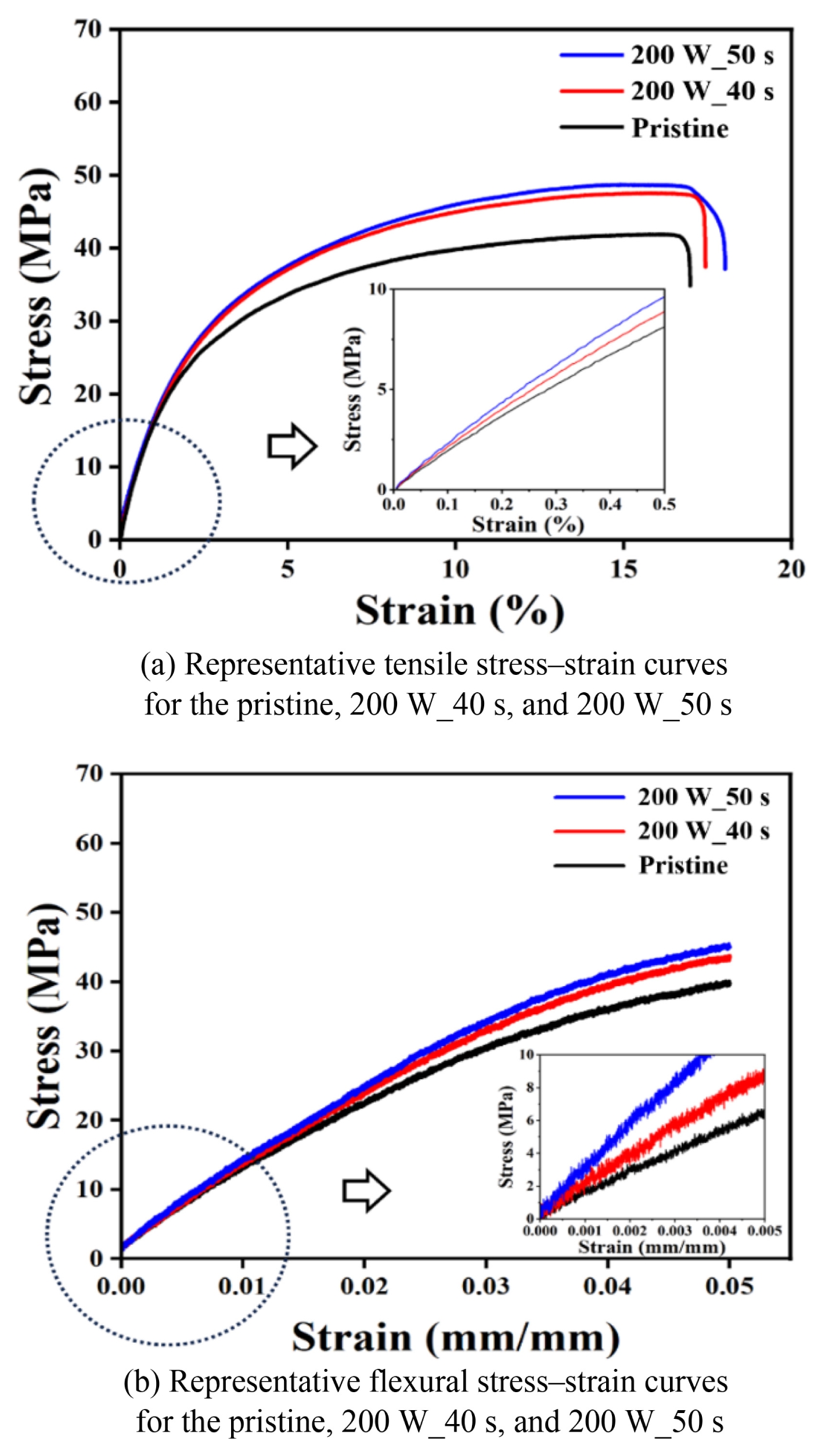
3.4 기계적 특성 분석
Microwave 조사에 따른 PA6/CF 복합체의 기계적 특성 변화를 평가하기 위해 인장 및 굴곡강도 시험을 수행하였다.
Fig. 13과 같이 초기 시편과 비교하여 Microwave 조사가 이루어진 시편(200 W_40 s, 200 W_50 s) 은 인장강도, 연신율 및 탄성계수 모두 향상된 특성을 나타냈다. 특히, 인장 강도는 초기 42.38 MPa에서 200 W_50 s 조건에서는 49.11 MPa로 약 15.9% 증가하였으며, 탄성계수는 605.24에서 671.21 MPa로 약 10.9% 증가하였다. 이는 XRD 분석과 동일한 경향성을 나타내며, Microwave 조사에 의해 적층 계면에서 분자간 확산을 유도함으로써 계면 접합이 강화되었고, 그 과정에서 결정화도 및 고밀도의 α결정상 비율이 증가하여 PA6/CF복합체의 인장강도와 탄성계수가 증가하였다고 판단된다. 굴곡강도 시험에서도 유사한 경향이 나타났으며, 초기 40.51 MPa에서 200 W_50 s 조건에서 44.39 MPa로 약 9.58% 증가하였다.
Table 5는 기계적 특성의 평균 값이며,
Fig. 14은 오차 범위를 포함한 막대 그래프이다. 오차 범위는 n = 5에서 각각의 표준편차이며, p > 0.05 범위로 측정되었다.
또한, PA 소재 특성상 수분으로 인한 물성 변화에 대한 영향을 평가하기 위해, 200 W_50 s 시편을 사용하여 Microwave 조사 직후, 상온-상압(25°C, 1 atm)에서 24 시간 보관 후 및 건조상태로 24시간 보관(Desiccator 보관) 후 세가지 샘플에 대해서 인장강도 및 연신율 평가를 추가로 진행하였다. 24시간 상온-상압(대기환경) 보관 샘플의 경우, 인장강도 48.49 MPa(연신율 17.52%)를 가졌고, 24시간 건조상태 보관 샘플은 46.73 MPa(연신율 17.21%)를 가짐을 확인했다. 이 수치는 Microwave 조사 직후 샘플의 48.46 MPa (연신율 17.52%)과 3 .5% 내의 차이를 보이는 것으로 확인되었다. 이를 통해 Microwave 조사 공정은 24시간 이내에서 PA 소재의 수분 함유량 및 이에 따른 기계적 물성 변화에 유의미한 영향을 미치지 않음을 확인하였다. 하지만, 기존 문헌들에서 PA 소재는 장기적인 수분 흡수에 따라 기계적 물성이 변화하는 것으로 보고된 바 있으므로, 향후 장기간(예: 2주 이상)에 대한 추가적인 기계적 안정성 평가가 필요함을 확인했다.
3.5 적층 계면 분석
적층 계면의 구조적 변화를 확인하기 위해 인장 시편 단면을 SEM (Scanning Electron Microscopy)을 통해 분석하였다.
Fig. 15은 초기 시편 및 200 W에서 각각 40초, 50초 Microwave를 조사시킨 SEM 이미지와, 경계 면적을 초록색 구간으로 도식화하여 나타낸 이미지이다.
Fig. 15(a)와 같이 Microwave 조사를 수행하기 전 초기 시편에서는 뚜렷한 층간 경계가 명확하게 관찰되었으며(Pristine → 56.82%), 이는 FDM 공정 특유의 적층 방식으로 인한 계면 접착력의 부족을 나타낸다. 프린팅 이후 각 적층 층은 경계선을 기준으로 분리된 형태로 존재하며, 계면 간 분자 확산이 미미하게 일어난 것으로 판단된다. 반면,
Figs. 15(a) 및
15(b) 같이 Microwave가 조사된 시편에서는 이러한 층간 경계가 점차 희미해지거나(200 W, 40 s → 33.16%) 거의 식별되지 않는 수준(200W, 50 s → 15.51%)으로 소실되었으며, 이는 계면 근처에서 고분자 사슬의 활발한 열적 유동성과 재배열이 발생했음을 보여준다. 이러한 결과는 Microwave 조사를 통해 적층 계면의 구조적 결함을 줄이고, 분자 간 확산과 재배열을 유도함으로써 FDM 방식으로 제조된 제품의 Z축 방향의 기계적 특성을 효과적으로 개선할 수 있음을 나타낸다.
4. 결론
본 연구에서는 FDM 방식으로 제조된 Nylon6/Carbon fiber 복합체에 대해, Microwave 조사를 활용한 적층 계면(Interlayer Interface) 강화 방법을 제안하고, 열적·구조적·기계적 특성 변화 및 형상 안정성 측면에서 그 유효성을 실험적으로 검증하였다. Microwave 출력과 조사 시간의 조절을 통해 적층 구조체에 국소적인 열 유동을 유도함으로써, 적층 계면의 고분자 사슬 이동성 증가, 결정 구조 재배열, 3D 형상 유지 효과를 이끌어냈으며, 이러한 변화가 계면의 접합 강도 향상 및 전체 기계적 성능 개선으로 이어짐을 확인하였다. 열화상 분석을 통해 도출된 최적 조건(200 W, 40-50초)은 PA6의 유리전이온도(Tg, 75°C)를 초과하되 녹는점(Tm, 188°C) 미만의 온도 범위에서 안정적으로 열을 전달하였으며, 이를 통해 형상을 유지하면서도 층간 계면 개선 효과를 극대화할 수 있었다. DSC 및 XRD 분석 결과, Microwave 조사는 결정화도 증가 및 α결정상 형성을 유도하며, 계면에서의 사슬 정렬과 밀도를 높이는 것으로 나타났다. 기계적 특성 평가에서는 인장 강도 및 굽힘 강도 모두 Microwave 조사 후, 증가하는 경향이 관찰되었으며, SEM 분석에서는 초기 시편에 비해 Microwave가 조사된 시편에서 층간 경계가 사라지고 연속적 모폴로지로 변화된 것이 관찰되었다. 이는 본 공정이 단순히 표면만 변화시키는 것이 아니라 계면 내부 구조 수준에서의 재배열과 융착이 실질적으로 일어났음을 뒷받침한다. 이러한 결과는 Microwave 조사가 단순한 비열적 처리 방법이 아닌, FDM 기반 적층 구조의 고질적인 한계인 Z-축 방향의 기계적 약화와 계면 취약성 문제를 효과적으로 해결할 수 있는 실질적 후처리 방법임을 시사한다. 또한 본 기술은 별도의 고가 장비나 소재 변경 없이도 적용 가능하다는 점에서 공정 단순화, 비용 절감, 상업적 확장성 측면에서 높은 산업적 유용성을 지닌다. 향후 연구에서는 본 기법을 다양한 고분자 및 복합소재 시스템에 적용하고 전도성 필러 (CNT, Graphene 등), 유전 특성이 다른 무기필러(Al2O3, BaTiO3 등)가 포함된 복합 재료에 대해서는 Microwave 에너지의 선택적 흡수와 분포 특성을 규명함으로써, 다양한 출력물로 응용 가능 범위를 크게 확장할 수 있을 것으로 기대된다.
FOOTNOTES
-
ACKNOWLEDGEMENT
본 연구는 한국생산기술연구원 ‘울산 주력사업과 연계한 저탄소·수소 벨류체인 고도화 핵심 기술개발(No. JK260010)’의 지원으로 수행되었습니다.
Fig. 1Schematic illustration of interlayer interface mitigation in FDM-fabricated specimens through microwave irradiation

Fig. 2Filament used for the FDM process. (a) Molecular structure of PA6/CF composited filament, (b) OM image of filament cross-section (×25), and (c) SEM image of filament crosssection (×1000)

Fig. 3Mark two 3D printer (Markforged Inc. USA)

Fig. 4Schematics for tensile, flexural test specimen
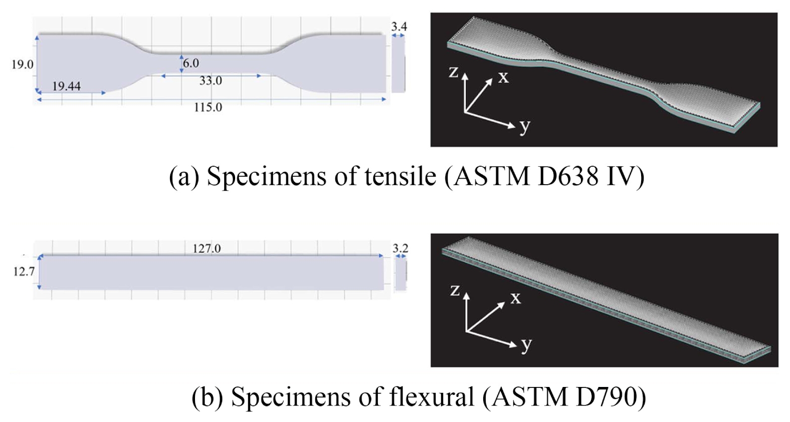
Fig. 5

Fig. 6
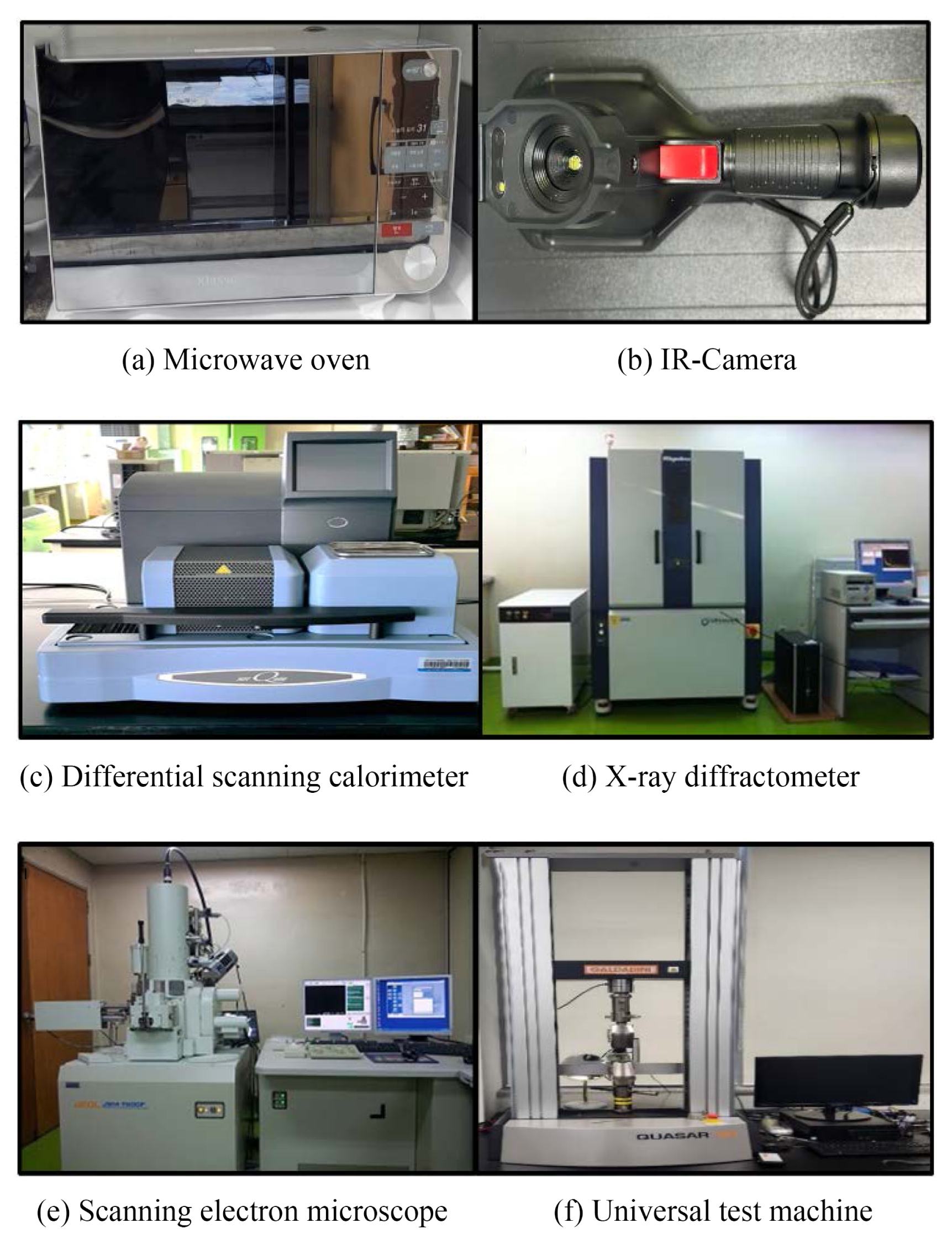
Fig. 7IR images at each condition are presented to visualize spatial surface temperature distribution and its relation to structural integrity. 200 W for 60 s and 200 W for 10 s exhibited localized melting at the center of the specimen, indicating concentrated heat accumulation
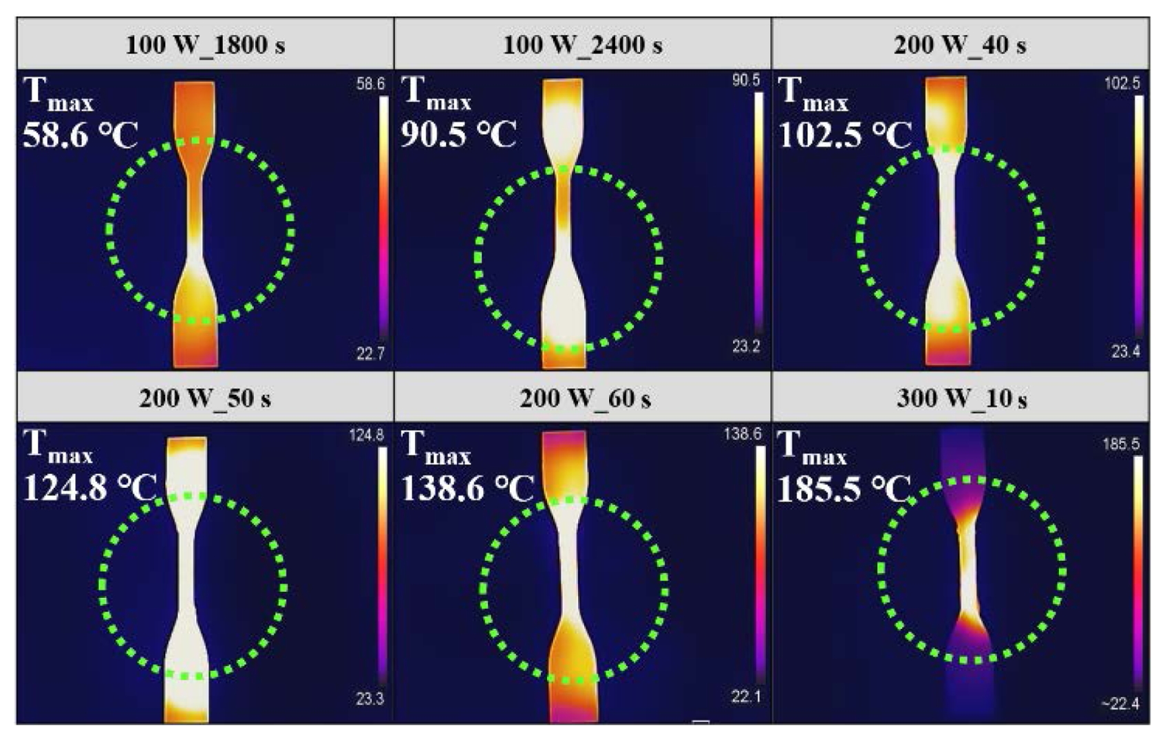
Fig. 8Shape of tensile specimens after microwave irradiation under different surface temperatures
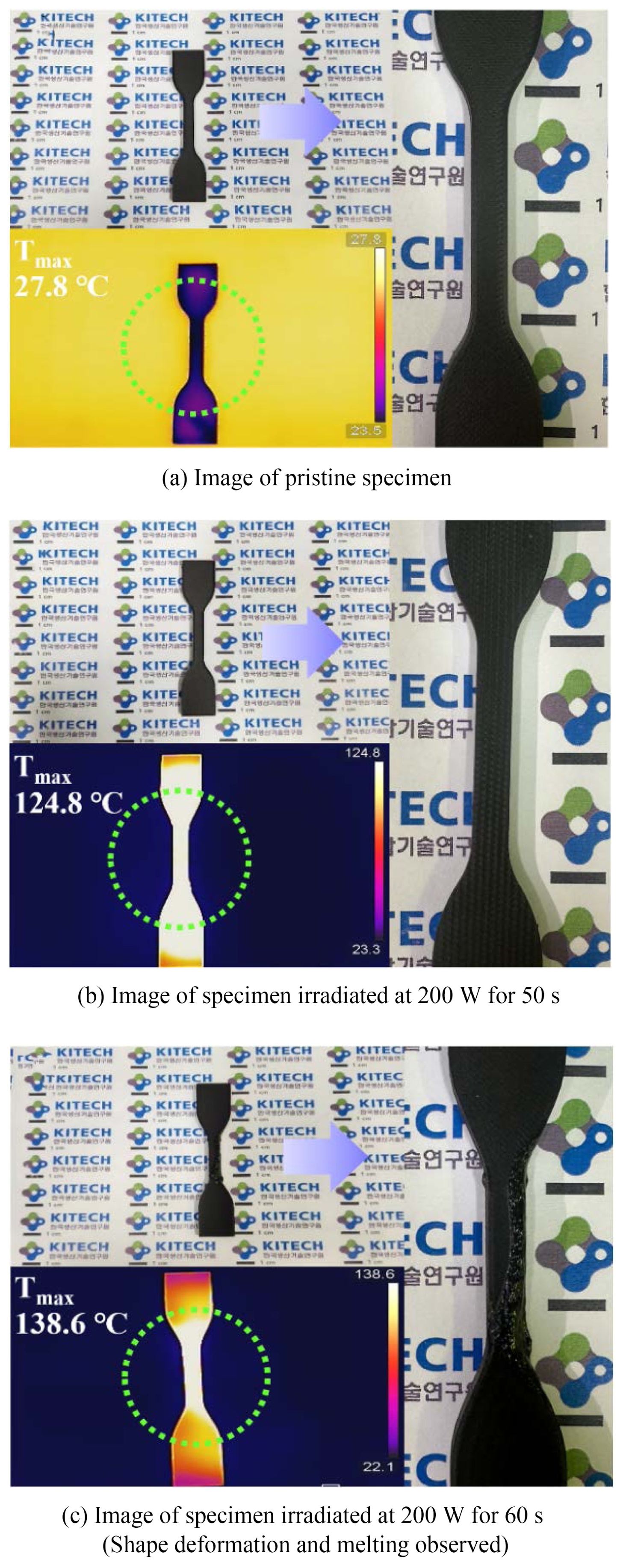
Fig. 9Process window map illustrating the threshold between shape retention and deformation of fabricated specimens under various microwave irradiation conditions
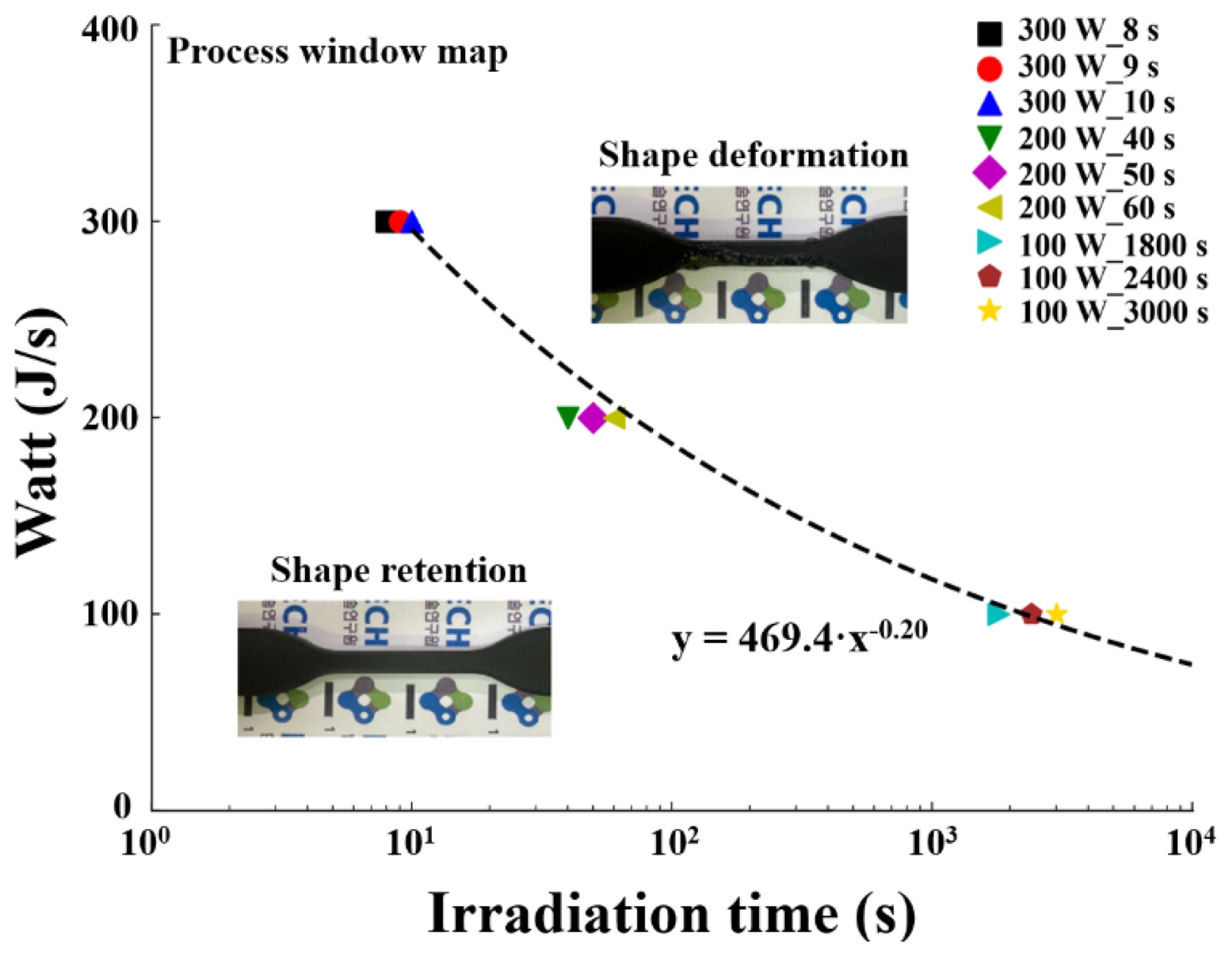
Fig. 10Surface temperature of tensile specimens fabricated by the standing-on-build orientation under microwave irradiation (200 W_ 40 s, 200 W_50 s, 200 W_60 s)

Fig. 11DSC 1st heating curve of 3D printed PA/CF composite, pristine and irradiation of microwave specimens

Fig. 12After microwave irradiation, the XRD pattern exhibited enhanced peak intensities, particularly at 2θ ≈ 20.1°, 21.4°, and 22.8°, corresponding to the γ (200), α1 (200), and α2 (202) crystal planes of PA6/CF composite

Fig. 13Mechanical property evaluation before and after microwave irradiation

Fig. 14Mechanical properties of 3D-printed PA/CF composites pristine and after microwave irradiation. Error bars represent standard deviation from five measurements (n = 5, p > 0.05)
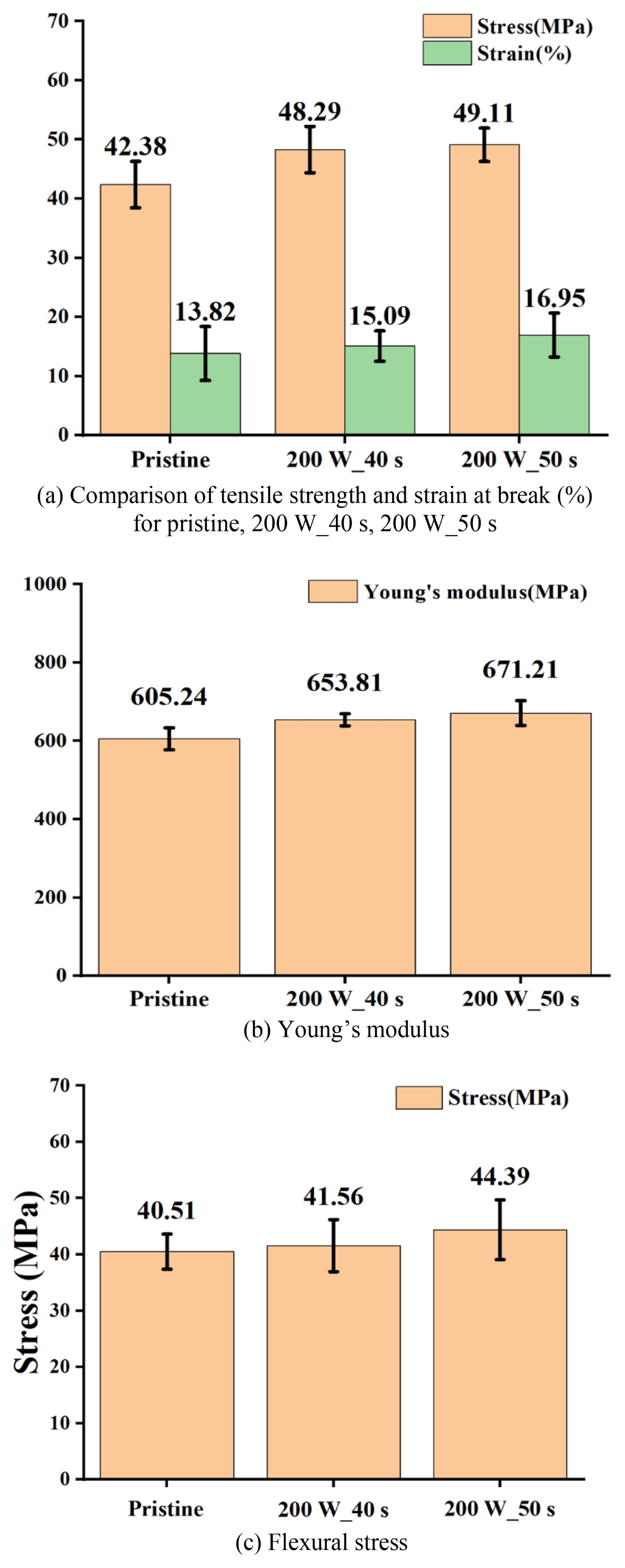
Fig. 15SEM images and quantified interlayer interface areas of FDM-fabricated PA6/CF parts before and after microwave irradiation. Green-highlighted regions indicate the visible interfacial boundaries between printed layers. The area ratio (%) represents the proportion of distinguishable interfaces relative to the total cross-sectional area
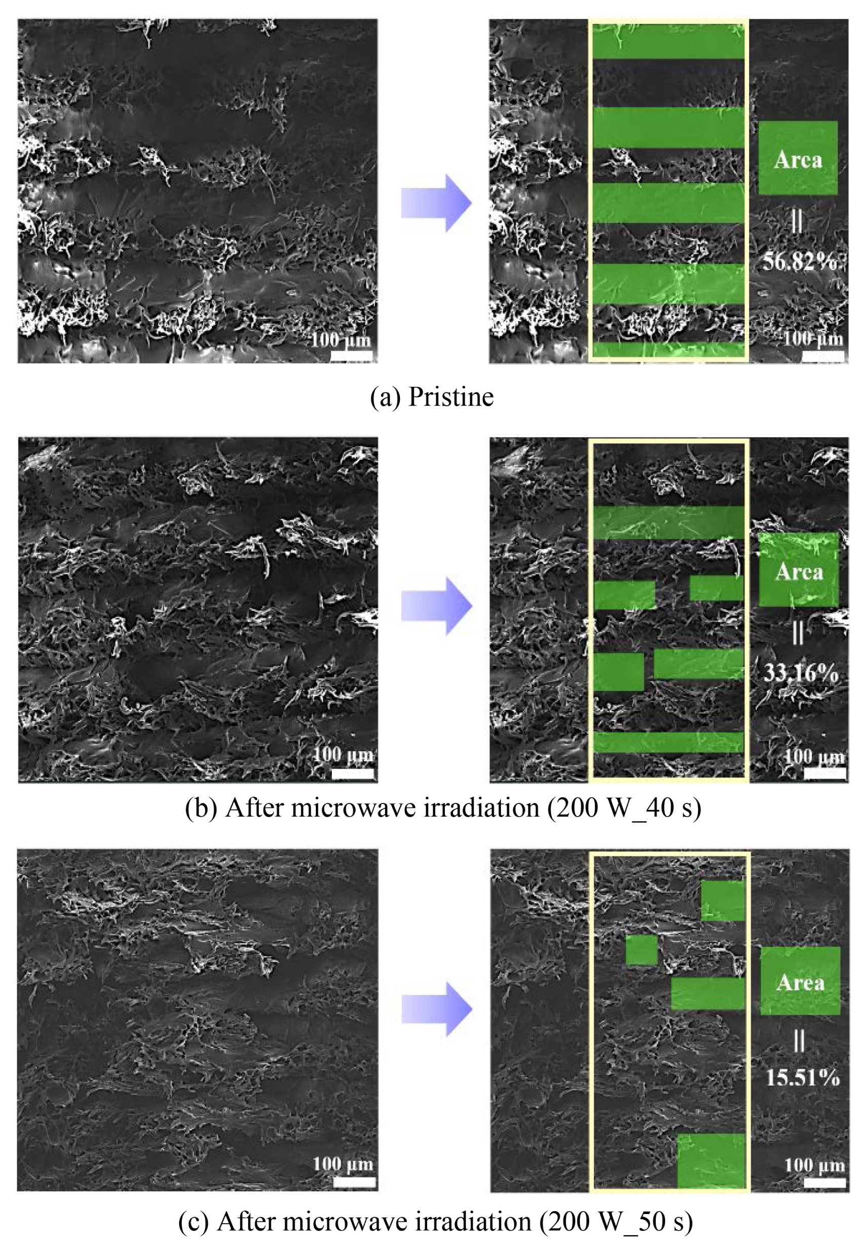
Table 1
Table 1
|
Parameter |
Value |
|
Nozzle diameter |
0.40 mm |
|
Nozzle temperature |
275°C |
|
Fill density |
100% |
|
Fill pattern |
Solid fill pattern |
|
Raster angle |
± 45° |
|
Layer thickness |
0.10 mm |
Table 2Surface temperature and shape deformation behavior of specimens under various microwave irradiation conditions (100, 200, and 300 W) and times
Table 2
|
Microwave power [W] |
Time [s] |
Surface temperature [°C] |
Shape deformation |
|
100 |
1,800 |
58.6 |
X |
|
100 |
2,400 |
90.5 |
X |
|
200 |
40 |
102.5 |
X |
|
200 |
50 |
124.8 |
X |
|
200 |
60 |
138.6 |
O |
|
300 |
10 |
185.5 |
O |
Table 3Thermal properties and crystallinity (Xc) of specimens pristine and after microwave irradiation
Table 3
|
Sample |
Tm [°C] |
ΔH [J/g] |
Xc [%] |
|
Pristine |
209.27 |
35.54 |
21.16 |
|
200 W_40 s |
210.91 |
36.95 |
21.99 |
|
200 W_50 s |
211.29 |
37.61 |
22.39 |
Table 4Relative crystalline phase (α, γ) fractions of PA6/carbon fiber composites after microwave irradiation
Table 4
|
Sample |
α1 [%] |
γ [%] |
α2 [%] |
|
Pristine |
7.76 |
9.53 |
8.72 |
|
200 W_40 s |
8.51 |
8.41 |
9.54 |
|
200 W_ 50 s |
9.38 |
8.69 |
10.53 |
Table 5Comparison of the mechanical properties table for pristine, 200 W_40 s, 200 W, 50 s
Table 5
|
Sample |
Tensile strength [MPa] |
Strain [%] |
Young’s modulus [MPa] |
flexural stress [MPa] |
|
Pristine |
42.38 |
13.82 |
605.24 |
40.51 |
|
200 W_40 s |
48.29 |
15.09 |
653.81 |
41.56 |
|
200 W_ 50 s |
49.11 |
16.95 |
671.21 |
44.39 |
REFERENCES
- 1. Choi, S. J., Bae, Y. H., Lee, I. H., Kim, H., (2018), Latest research trends of 3D printing in Korea, Journal of the Korean Society for Precision Engineering, 35(9), 829-834.
- 2. Kim, M.-S., Seo, S.-H., Kim, H.-I., Ahn, S.-H., (2016), Hybrid 3D printing and casting manufacturing process for fabrication of smart soft composite actuators, Journal of the Korean Society for Precision Engineering, 33(1), 77-83.
- 3. Jeong, S., Sim, J., Kim, H., Shin, D., Hong, D., (2017), Application of lom for freeform architecture, Journal of the Korean Society for Precision Engineering, 34(12), 903-909.
- 4. Yoo, C.-J., Kim, H., Park, J.-H., Yun, D.-H., Shin, J-K, Shin, B-S, (2016), Study of optimal process conditions of 3D porous polymer printing for personal safety products, Journal of the Korean Society for Precision Engineering, 33(5), 333-339.
- 5. Giubilini, A., Siqueira, G., Clemens, F. J., Sciancalepore, C., Messori, M., Nystrom, G., Bondioli, F., (2020), 3D-printing nanocellulosepoly (3-hydroxybutyrate-co-3-hydroxyhexanoate) biodegradable composites by fused deposition modeling, ACS Sustainable Chemistry & Engineering, 8(27), 10292-10302.
- 6. Ou-Yang, Q., Guo, B., Xu, J., (2018), Preparation and characterization of poly (butylene succinate)/polylactide blends for fused deposition modeling 3D printing, ACS Omega, 3(10), 14309-14317.
- 7. Xu, N., Ye, X., Wei, D., Zhong, J., Chen, Y., Xu, G., He, D., (2014), 3D artificial bones for bone repair prepared by computed tomography-guided fused deposition modeling for bone repair, ACS Applied Materials & Interfaces, 6(17), 14952-14963.
- 8. Waheed, S., Cabot, J. M., Smejkal, P., Farajikhah, S., Sayyar, S., Innis, P. C., Beirne, S., Barnsley, G., Lewis, T. W., Breadmore, M. C., (2019), Three-dimensional printing of abrasive, hard, and thermally conductive synthetic microdiamond–polymer composite using low-cost fused deposition modeling printer, ACS Applied Materials & Interfaces, 11(4), 4353-4363.
- 9. Chen, Q., Han, L., Ren, J., Rong, L., Cao, P., Advincula, R. C., (2020), 4D printing via an unconventional fused deposition modeling route to high-performance thermosets, ACS Applied Materials & Interfaces, 12(44), 50052-50060.
- 10. Deokar, S., Kumar, N., Singh, R. P., (2025), A comprehensive review on smart manufacturing using machine learning applicable to fused deposition modeling, Results in Engineering, 26, 104941.
- 11. Nadgorny, M., Ameli, A., (2018), Functional polymers and nanocomposites for 3D printing of smart structures and devices, ACS Applied Materials & Interfaces, 10(21), 17489-17507.
- 12. Xiao, X., Chen, J., Wang, K., Yu, Y., Wei, K., (2023), Multimaterial additively manufactured metamaterials functionalized with customizable thermal expansion in multiple directions, ACS Applied Materials & Interfaces, 15(40), 47434-47446.
- 13. Lee, S., Kim, J. H., Wajahat, M., Jeong, H., Chang, W. S., Cho, S. H., Kim, J. T., Seol, S. K., (2017), Three-dimensional printing of silver microarchitectures using newtonian nanoparticle inks, ACS Applied Materials & Interfaces, 9(22), 18918-18924.
- 14. Diniță, A., Neacşa, A., Portoacă, A. I., Tănase, M., Ilinca, C. N., Ramadan, I. N., (2023), Additive manufacturing post-processing treatments, a review with emphasis on mechanical characteristics, Materials, 16(13), 4610.
- 15. Galos, J., (2021), Microwave processing of carbon fibre polymer composites: A review, Polymers and polymer Composites, 29(3), 151-162.
- 16. Sohn, M., Kim, Y.-S., Na, J., Kim, M.-S., Ju, B.-K., Lee, T.-I., (2024), Microwave bonding of thin polymer substrates using carbon nanotubes for flexible interconnections, ACS Applied Nano Materials, 7(14), 16534-16541.
- 17. Kim, N. D., Metzger, A., Hejazi, V., Li, Y., Kovalchuk, A., Lee, S.-K., Ye, R., Mann, J. A., Kittrell, C., Shahsavari, R., (2016), Microwave heating of functionalized graphene nanoribbons in thermoset polymers for wellbore reinforcement, Acs Applied Materials & Interfaces, 8(20), 12985-12991.
- 18. Bhandavat, R., Kuhn, W., Mansfield, E., Lehman, J., Singh, G., (2012), Synthesis of polymer-derived ceramic Si (B) CN-carbon nanotube composite by microwave-induced interfacial polarization, ACS Applied Materials & Interfaces, 4(1), 11-16.
- 19. Vreeland, R. F., Laude, N. D., Lambert, S. M., Heien, M. L., (2014), Microwave-plasma dry-etch for fabrication of conducting polymer microelectrodes, Analytical chemistry, 86(3), 1385-1390.
- 20. Ai, J.-R., Li, S., Vogt, B. D., (2022), Increased strength in carbonpoly (ether ether ketone) composites from material extrusion with rapid microwave post processing, Additive Manufacturing, 60, 103209.
- 21. Zhang, H., Zhi, J., Lu, X., Peng, X., Gao, X., Yang, Y., Liu, Z., Cao, Y., Liu, Q., Sun, Y., (2024), A new mechanism of mechanical reinforcement for 3D printing CF/PA12 composite based on microwave treatment, Polymer Composites, 45(12), 10852-10864.
- 22. Konstantopoulos, G., Maroulas, P., Dragatogiannis, D. A., Koutsoumpis, S., Kyritsis, A., Charitidis, C. A., (2021), The effect of interfacial resistance and crystallinity on heat transfer mechanism in carbon nanotube reinforced polyethylene, Materials & Design, 199, 109420.
- 23. Zhang, X., Gohn, A., Mendis, G., Buzinkai, J. F., Weigand, S. J., Rhoades, A. M., (2021), Probing three distinct crystal polymorphs of melt-crystallized polyamide 6 by an integrated fast scanning calorimetry chip system, Macromolecules, 54(16), 7512-7528.
- 24. Yan, X., Imai, Y., Shimamoto, D., Hotta, Y., (2014), Relationship study between crystal structure and thermal/mechanical properties of polyamide 6 reinforced and unreinforced by carbon fiber from macro and local view, Polymer, 55(23), 6186-6194.
Biography
- Si Woo Kim
Researcher in Smart Forming Process Group, KITECH. His research interests are composite materials and additive manufacturing.
- Ho Geun Nam
Researcher in Smart Forming Process Group, KITECH. His research interests are composite materials and additive manufacturing.
- Jong Wan Ko
He received his Ph.D. degree in Materials Science and Engineering from the Korea Advanced Institute of Science and Technology (KAIST), South Korea. He is currently a Principal Researcher at the Korea Institute of Industrial Technology (KITECH). His current research interests focus on industrial additive manufacturing materials, including metal powders and carbon-based polymer composites, as well as their processing technologies. He has been actively involved in national R&D projects related to large-scale additive manufacturing and is also participating in standardization efforts in the field.