ABSTRACT
Dual-drive H-type gantry stages, powered by direct-drive linear motors, are commonly used in precision industrial applications that require high positioning accuracy over a large workspace. The cross-arm rigidly couples the two parallel axes, making strict synchronization control essential for maintaining positioning accuracy. Conventional master-master control treats the coupling effects as disturbances without accounting for the synchronization of the two motors. As a result, its performance deteriorates significantly under non-uniform load distribution, payload rotation, and directly applied torque disturbances, all of which necessitate reliable synchronization control. This study proposes a synchronization control scheme that integrates a sliding-mode controller with an uncertainty and disturbance estimator (SMC-UDE) and a feedforward torque compensator for the inertial torque induced by payload rotation. The proposed controller was implemented on a Hardware-in-the-Loop (HIL) simulator constructed with two parallel voice coil motors, and its performance was experimentally validated on the testbed. The HIL experimental results demonstrate that the SMC-UDE controller with feedforward torque-disturbance compensation achieves a quicker settling time compared to the conventional master-master control strategy. Additionally, it effectively suppresses disturbances generated by a rotary motor attached to a payload, thereby maintaining synchronization accuracy under disturbed conditions.
-
KEYWORDS: H-type gantry stage, SMC-UDE, Torque disturbance compensator, Synchronization error
-
KEYWORDS: H-형 갠트리 스테이지, 슬라이딩 모드 제어기-불확실성/외란 추정기, 토크 외란 보상기, 동기오차
1. Introduction
A dual-drive H-type gantry stage is composed of two parallel linear motors and a cross-arm, connected to both motors through a rigid joint. Gantry stages provide high positioning accuracy relative to their large workspace and are widely used in precision industrial applications such as PCB assembly, automated optical inspection, and flat-panel display manufacturing. In a dual-drive configuration where a single axis is driven by two motors, synchronization error, defined as the relative position error between the two motors, can affect precision motion. This synchronization error can be induced by non-uniform load distribution, mismatches in the motor and drive characteristics, and torque disturbance generated by the rotary motor mounted on the payload. A large synchronization error can induce significant stress in the cross-arm and bearings, which can result in degraded positioning accuracy and permanent mechanical damage. To address this issue, active control to suppress synchronization error is becoming increasingly emphasized [
1-
5].
Conventional control methods for dual-drive gantry stages include PID-based master–slave and master–master control scheme. In the master–slave control strategy, the Y1 motor serves as the master, and its position is used as the position command for the Y2 motor. Despite the simple system configuration of master–slave control, the delayed response of the slave motor relative to the master leads to a large position error between the two motors, indicating poor synchronization performance. In contrast, the master–master control strategy improves synchronization performance by allowing both actuators to share an identical position command. In this strategy, each control loop is individually tuned to achieve similar bandwidth and tracking performance, but it has a fundamental limitation in that the coupling between the two parallel axes is not directly addressed. This limitation leads to increased synchronization error and degraded stability under model uncertainties or external disturbances, limiting its use in precision applications.
To overcome these coupling issues, several control strategies have been proposed to reduce synchronization errors. A modelbased decoupling control was proposed to reduce coupling, therefore improving motion performance [
1]. An improved master–slave structure combined with adaptive robust control and cogging-force compensation was also introduced to enhance synchronization accuracy [
2]. A composite positioning control and a synchronization scheme based on coupled dynamics were further presented to achieve high-speed and high-precision motion control of the gantry stage [
3]. A method that incorporates planar translational and rotational dynamics into a MIMO model with adaptive robust synchronization control was proposed to improve internal force regulation and synchronization performance [
4]. However, prior studies rely solely on feedback-based approaches and do not directly reject torque disturbances. This leads to limited tracking performance in applications such as rotary-type PCB assembly machines, where torque disturbances are directly applied.
In this study, a Sliding Mode Controller with Uncertainty Disturbance Estimator (SMC-UDE) and a torque disturbance compensation method, which directly suppress the synchronization error caused by torque disturbances, are proposed. SMC is adopted to ensure robustness against model uncertainties and external disturbances, and the UDE is incorporated to estimate lowfrequency disturbances in real time and to suppress excessive switching in sliding-mode control. In addition, a feedforward torque disturbance compensation method is proposed to enhance synchronization performance, by directly accounting for the torque disturbance. Note that the modeling error occurring at feedforward compensator is also estimated by the UDE, ensuring robustness. To ensure reliable verification of the control performance, a Hardwarein-the-Loop (HIL) simulator was constructed to enable repeated experimentation without damage to the actual equipment. The simulator was configured to reflect the model uncertainties, the non-uniform load distribution and mechanical coupling inherent to the dual-drive structure, which allows evaluation under realistic dynamic conditions. Through this HIL simulation, the proposed controller was verified to reduce both the settling time and the synchronization error compared to the conventional controller.
The remainder of this paper is organized as follows. In Section 2, the configuration of the HIL simulator and the procedure for modeling the 2-DOF model of the gantry stage are introduced. In Section 3, the SMC-UDE controller and the torque-disturbance compensation method are proposed based on the dynamic model. In Section 4, experimental results are provided to verify the improved tracking and synchronization performance of the proposed method. Finally, the conclusions of this study are presented in Section 5.
2. HIL Simulator Design and System Modeling
2.1 HIL Simulator Design
In this study, a Hardware-in-the-Loop simulator was used to validate the proposed control method. The position tracking performance is influenced by several factors, such as the nonuniform load distribution and the differences in the dual-drive motor characteristics. These lead to potential decrease in mechanical stability of the system, and in severe cases, the physical limits of the gantry stage may be exceeded, resulting in abnormal operation and direct mechanical damage such as excessive wear or component failure. To prevent such problems and verify the control performance in a safer environment, a compact and simplified HIL stage was designed to simulate the actual dynamics of the gantry system. The simulator reflects the dynamics of the general system, including load distribution and cross-arm rotation, while minimizing the risk of physical damage during test failures, therefore reducing experimental costs [
6-
8]. Furthermore, nonlinear dynamics such as friction and Coriolis effects, which are often neglected in the software simulations, are reflected in the HIL environment, resulting in reliable validation of the proposed control method.
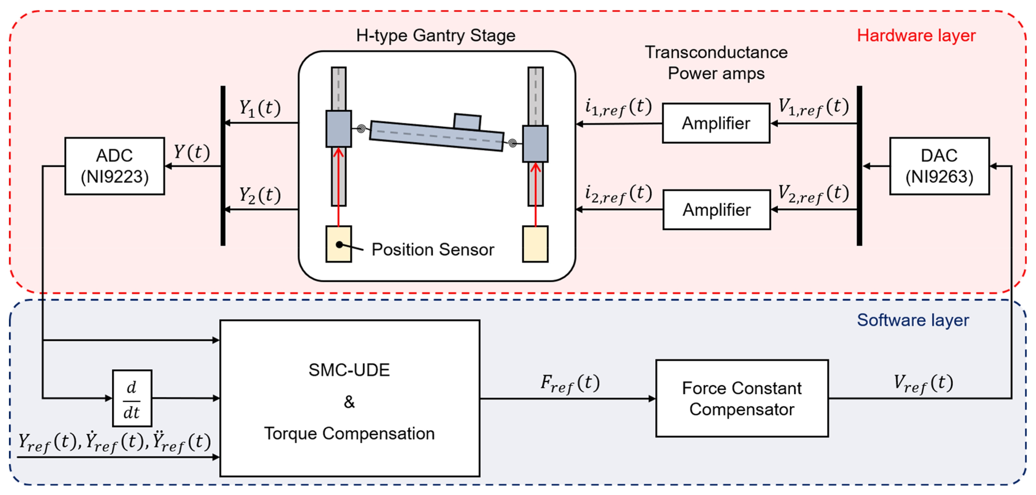
Fig. 1 shows the overall configuration of the HIL simulator. The simulator consists of a hardware layer, which emulates the physical behavior of the H-type gantry stage, and the software layer that performs control input calculation and signal processing. These two layers are interconnected through an ADC (Analog-to-Digital Converter) and a DAC (Digital-to-Analog Converter), forming an integrated simulation system. The hardware layer includes an Htype gantry stage composed of two voice coil motors and a crossarm. The displacements of each motor,
Y1 and
Y2, are measured by position sensors, and the measured signals are transmitted to the software layer through the ADC module (National Instruments, NI 9223). The voltage commands calculated in the controller,
V1,ref and
V2,ref, are output as analog voltages through the DAC module (NI 9263) and then converted into current commands,
i1,ref and
i2,ref, by the transconductance power amplifiers. In the software layer, the reference trajectory
Yref and its derivatives,
Ẏrefand ,
Ÿrefare provided as inputs to the real-time controller (NI cRIO-9043), which runs deterministically at 5 kHz. The proposed control method is executed in real time to compute a reference force command. The generated force command is converted into voltage commands through the force constant compensator, which compensates for the position-dependent force constant of the voice coil motors. As a result, the input signals
Vref for each driving motor are obtained. Through this closed-loop structure, the HIL simulator provides an environment in which the synchronization error and the position-tracking performance of the controller can be observed in real time.
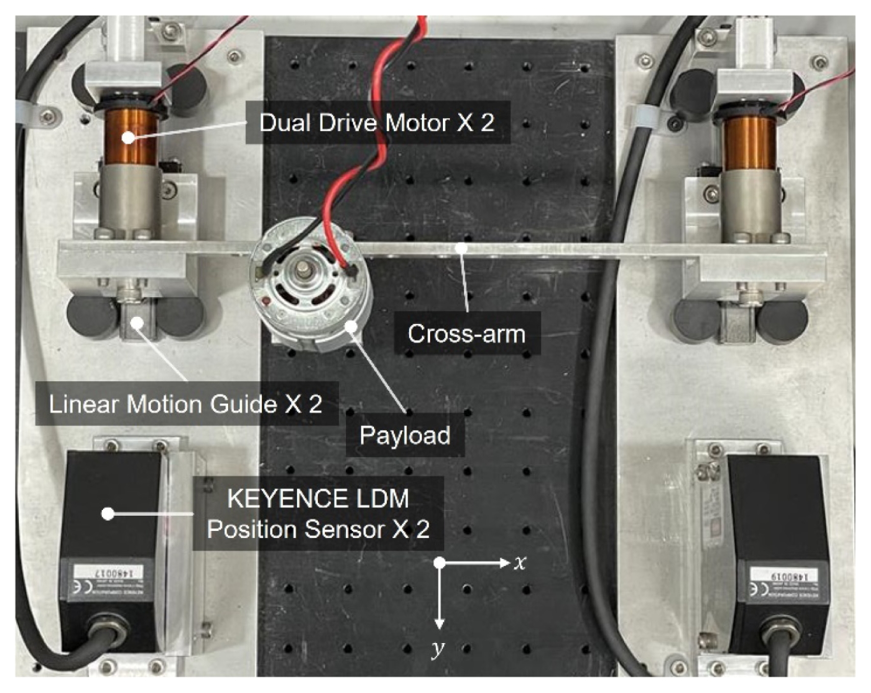
Fig. 2 shows the actual configuration of the VCM-based gantry stage included in the hardware layer. The stage is driven by two voice coil motors (Thorlabs, VC250) that are connected through a cross-arm and move along the y-axis on linear motion guides. A payload with a rotary motor is attached at an off-center position on the cross-arm, emulating the non-uniform load distribution of a conventional gantry system during operation. The positions of each motor are measured using laser displacement sensors (Keyence, LK-G80), enabling accurate position control of the system.
2.2 Dynamic Modeling
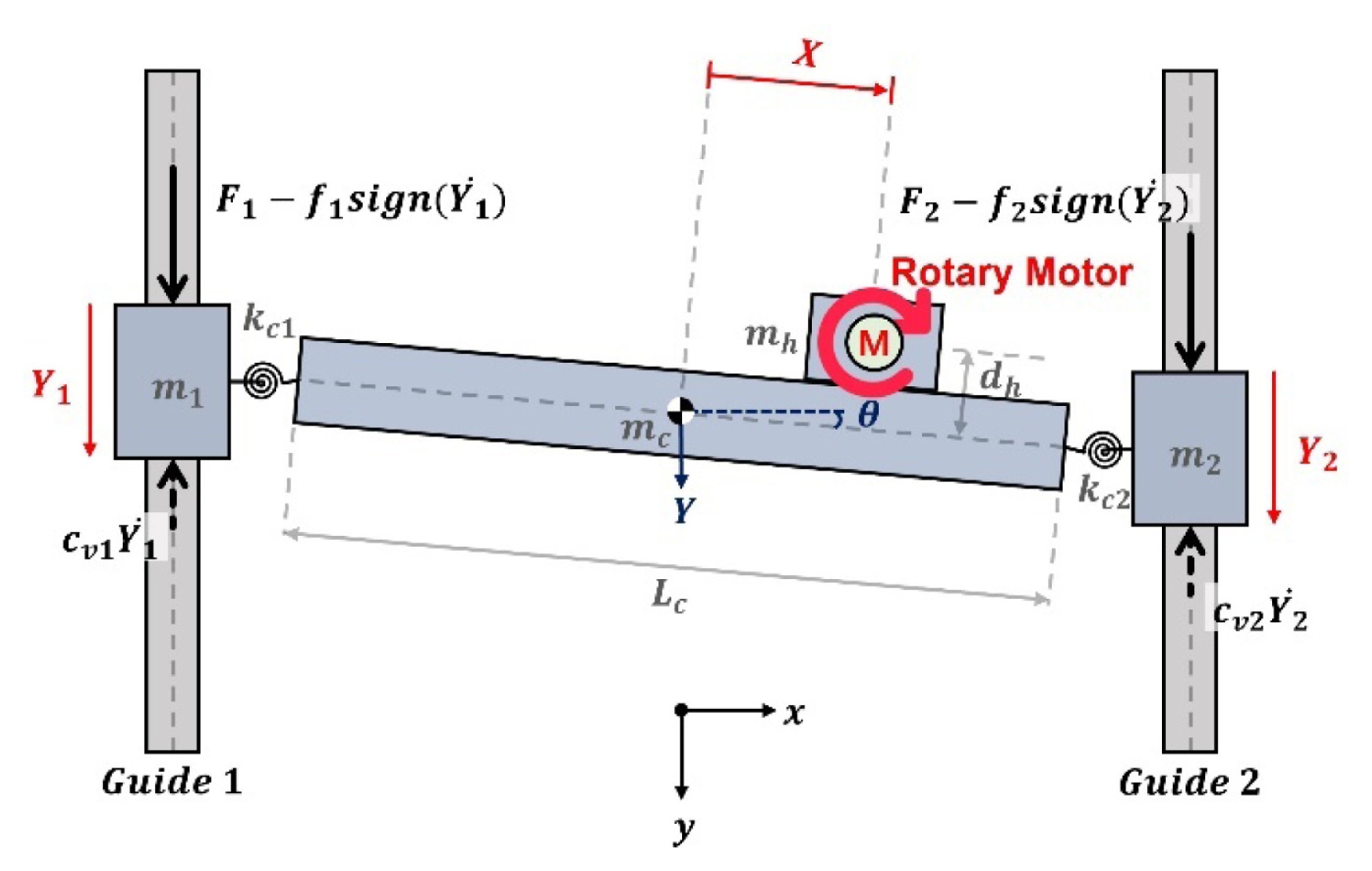
Fig. 3 presents the 2-DOF equivalent model of the dual-drive VCM-based gantry stage. The dynamics of the gantry stage include both translational and rotational motion resulting from thrust imbalance between the two motors and mechanical asymmetry. Accordingly, the motor position coordinates (
Y1,
Y2) were replaced by the equivalent coordinate system (
Y, θ), where
Y and
θ denote the translational displacement and rotational angle of the cross-arm center, respectively.
This coordinate system enables the motion of the two actuators to be expressed as translational and rotational components, simplifying the dynamic modeling process. The coordinate transformation is given in
Eq. (1), and the dynamic equation of the gantry stage is derived using the Lagrange-Euler formulation.
where Lc is the length of the cross-arm. The Lagrange-Euler formulation requires defining the energy components associated with the system dynamics before deriving the equations of motion. These components are the kinetic energy T, the elastic potential energy V, and the Rayleigh dissipation function D, which are written as:
where the utilized parameters are summarized in
Table 1. The forces applied to the gantry stage, expressed in the coordinate system (
Y, θ), are given as:
where
M, C, K, and
H represent the mass, viscous damping, stiffness, and Coriolis and centripetal matrices, respectively, and
F denotes the force vector. This equation is simplified by approximating cos
θ ≈ 1 and sin
θ ≈ 0, considering that the rotation of the crossarm is mechanically constrained within a very small range. In the experiments, the maximum rotation angle and angular velocity are limited to
θmax = 0.14 mrad and
̇θmax = 48 mrad/s, respectively, which justifies this assumption and allows the Coriolis and centripetal terms to be neglected. The detailed derivation and simplification procedure can be found in [
1]. The simplified equation of motion can be expressed as
Eq. (8).
Here,
Ms, Cs, and
Ks denote the simplified mass, damping, and stiffness matrices given in
Eqs. (10),
(11), and
(12), respectively, and
Fs is the simplified force vector.
where
mtotal is the sum of the masses of the cross-arm, payload, and each VCM. The generated control forces are transformed into
F1 and
F2, and applied to the MIMO plant represented by
G11,
G12,
G21, and
G22, as shown in
Fig. 4. Note that
G21 and
G12 are the transfer functions that represent the coupling effect between two parallel axes. Based on this model, the proposed control method is derived to robustly reduce the synchronization error, as presented in the following section.
3. Control System Design
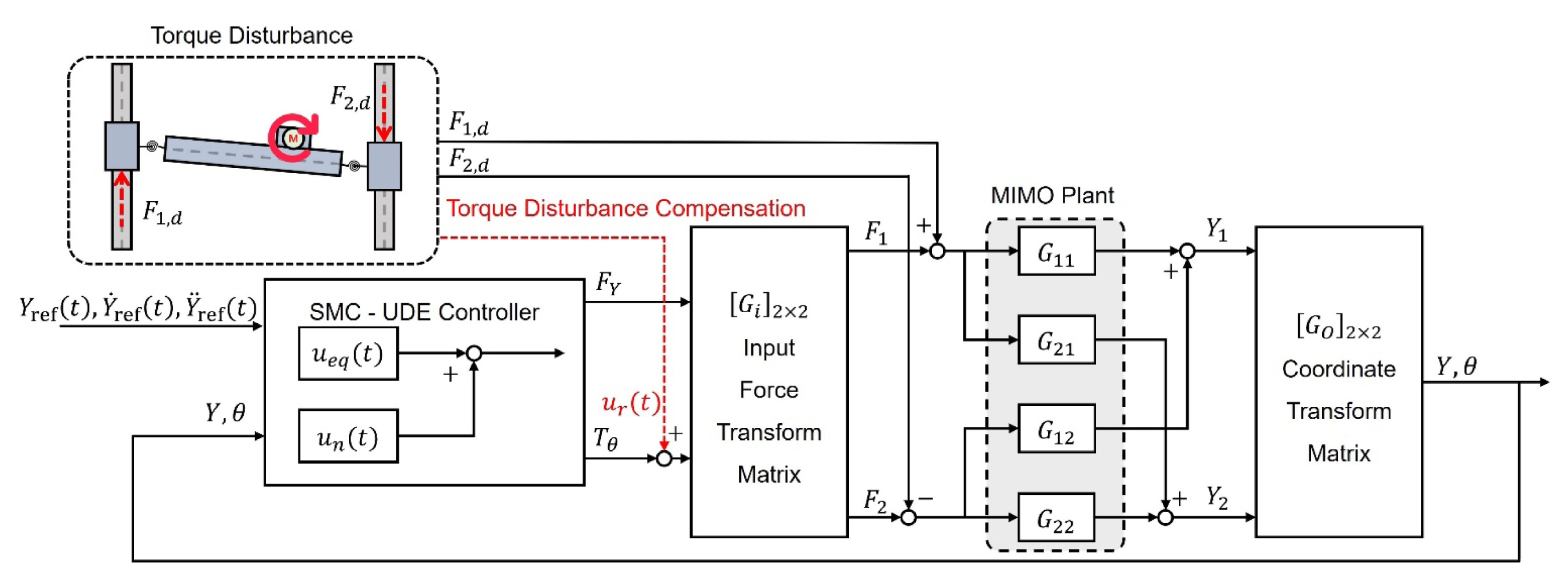
Fig. 4 illustrates the block diagram of the controller designed to perform position control of the gantry stage and to compensate for the torque disturbance. First, a Sliding Mode Controller (SMC) combined with an Uncertainty and Disturbance Estimator (UDE) is designed. For the controller design, the system dynamics
Eq. (8) is reformulated as:
The disturbance d(t) is assumed to be bounded, satisfying |di(t)| ≤ di,max, where di,max > 0 is an unknown but finite constant. To perform position tracking of the gantry stage, the tracking error e(t) and its time derivative are defined as:
To estimate the velocity (q̇), a 500 Hz cut-off frequency highpass filter was used for the differentiation. In sliding mode control, a sliding surface is introduced to impose the desired convergence characteristics on the error dynamics. A first-order sliding surface is defined as:
where λi > 0 is a sliding-surface gain that specifies the convergence rate once the sliding condition, S(t) = 0, is reached. The error dynamics are expressed as:
ensuring that
e(
t) decreases exponentially and converges to zero. To derive the control input, the time derivative of the sliding surface in
Eq. (15) is obtained as:
By substituting the system dynamics in
Eq. (13) into
q̈(
t), the following expression is obtained:
The equivalent control is obtained by neglecting the lumped disturbance term
d(
t), following the approach adopted in [
9,
10].
where ηi > 0 denotes the switching gain. To improve robustness against disturbances, the equivalent control input ueq(t) is supplemented with an additional compensation term. In conventional sliding mode control, this additional term is used to ensure that the sliding condition is satisfied. Therefore, the total control input is defined as:
The term un(t) is employed to compensate for the lumped disturbance and model uncertainties. In this study, the compensation input is selected as:
The UDE is used to estimate the external disturbance and model uncertainties of the system. As presented in [
9], the disturbance
d(
t) can be recovered by using a low-pass filter that has unity DC gain and negligible phase shift at low frequencies. Therefore, only the low-frequency components of the disturbance are passed through the filter, while the high-frequency noise is attenuated. Using this filter structure, the lumped disturbance and uncertainties are estimated in the following convolution form:
where
gf(
t) denotes the impulse response of the low-pass filter, and the operator* represents convolution. Through this operation, low frequency components of
d(
t) can be recovered. By substituting
Eq. (20), which is the sum of the equivalent control obtained in
Eq. (19) and the compensation term
un(
t) defined in
Eq. (21), into
Eq. (18), the expression becomes:
where
d̃(
t) denotes the UDE estimation error. By using the estimated disturbance
d̂(
t) defined in
Eq. (22), the expression can be rewritten as:
A first order low-pass filter is selected in this paper, with the transfer function given as:
Here, τ is the time constant that determines the filter bandwidth. A smaller τ improves disturbance estimation accuracy but increases sensitivity to high-frequency noise. Therefore, τ is carefully tuned to the minimum value that avoids excessive vibration, thereby achieving a balance between estimation performance and noise robustness. By applying this transfer function and solving for d̂(t), the compensation input un(t) used for disturbance rejection is obtained as:
By combining the control inputs obtained in (19) and (26), the final control input u(t) is derived as follows.
To analyze the stability of the control method, the following Lyapunov candidate function is selected.
By the characteristics of the low-pass filter, which ensures zero steady-state estimation error for the lumped disturbance, d̃(t) asymptotically converges to zero as t → ∞, thereby reducing V̇ to -ηST(t)S(t). Since this term is zero only when S = 0 and negative otherwise, V̇ is a negative definite function. As V is positive definite, this establishes the asymptotic stability of the system. This implies that the sliding surface S(t) asymptotically converges to zero as t → ∞.
The utilized parameters of the SMC-UDE controller are summarized in
Table 2. In addition to the SMC-UDE, torque feedforward control is utilized simultaneously for torque disturbance compensation to decrease synchronization error of the gantry stage. The torque disturbance induced by payload rotation has a particularly strong influence on the synchronization error. Although the SMC-UDE controller effectively suppresses the coupling effects of the dual-drive system, it cannot directly reject this rotational torque. However, the payload torque can be estimated from the motor torque constant and the reference current, allowing the disturbance to be compensated through feedforward compensation.
The motor torque generated at the payload can be estimated as:
where Kt is the motor torque constant and im(t) is the motor current. This torque generates a reaction torque of equal magnitude but opposite direction in the gantry stage, and the resulting reaction torque is given as:
Since the input of the gantry stage is composed of translational and rotational components,
Fs = [
FYs,
Tθs]
T, the rotational term in
Eq. (9) includes the motor reaction torque
Tr. Therefore, the rotational input and overall system dynamics that incorporate the torque disturbance can be expressed as:
Using the torque constant Kt of the rotary motor and the reference current, the reaction torque can be predicted. Based on this estimated reaction torque T̂r, a feedforward compensation input can be generated by applying a control torque with the same magnitude but opposite direction. The corresponding control input ur(t) and the final control input u(t) are expressed as:
Such feedforward control directly compensates for the torque disturbance, improving synchronization quality. This also reduces the UDE estimation error (d̃(t) = d(t) - (gf*d)(t)), resulting in faster convergence to the sliding surface and further enhancing synchronization performance.
4. Experimental Result
In this section, the experimental results are presented to evaluate the performance of the control methods. First, the tracking performance of the SMC-UDE controller is compared to the master–master controller. The servo performances of these two control methods are compared during trajectory tracking control. Next, the dual-drive motors were controlled to remain at standstill while the torque disturbance was applied. The effect of the disturbance is examined while the influence of tracking motion is excluded. Finally, the synchronization error of the system is examined under the same trajectory tracking operation, with and without the torque disturbance, as well as with disturbance compensation. This comparison clarifies how the reduction of torque disturbance influences the synchronization error.
4.1 Trajectory Tracking Comparison of the SMC-UDE and Master-master Controllers
To compare the position control performance of each controller, experiments were conducted using the SMC-UDE controller and the conventional master–master controller under the same trajectory. The reference trajectory follows a fourth-order polynomial profile designed with a maximum acceleration of 10,000 mm/s², a maximum velocity of 300 mm/s, and a travel length of 5 mm. In the master-master controller, each position controller of VCM was designed by a linear lead–lag controller, and the position control bandwidth was set to 50 Hz.
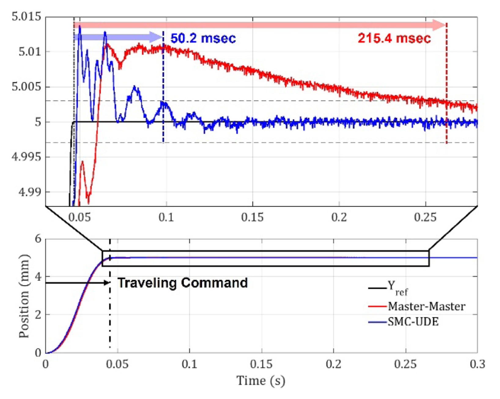
Fig. 5 presents the experimental results of the trajectory tracking control. The results indicate how quickly each control method reaches the target position. The lower plot shows the position responses over the entire travel range. The upper plot presents a magnified view of the settling phase, enabling a direct comparison of the settling times of the two controllers. The master–master controller reaches the 3
m band in approximately 215.4 ms, whereas the SMC-UDE controller converges to the same positioning accuracy level in only 50.2 ms, which corresponds to a reduction of approximately 76.7% compared to the conventional master– master controller.
This improvement is mainly due to two factors. First, the enhanced robustness of the SMC-UDE controller to disturbances and model uncertainties. Second, the structural difference between the two control methods, where the master–master controller does not directly control the rotation while the SMC-UDE controller is designed to directly control both the translation and rotation simultaneously.
4.2 Experimental Validation of the Proposed Compensation Method
Although the SMC-UDE controller controls the rotational motion of the gantry stage, any torque disturbance can still induce a transient position difference between the two motors. To examine the effect of torque disturbance, the synchronization error is evaluated with and without the torque-disturbance compensation while the dual-drive motors are controlled to remain at standstill.
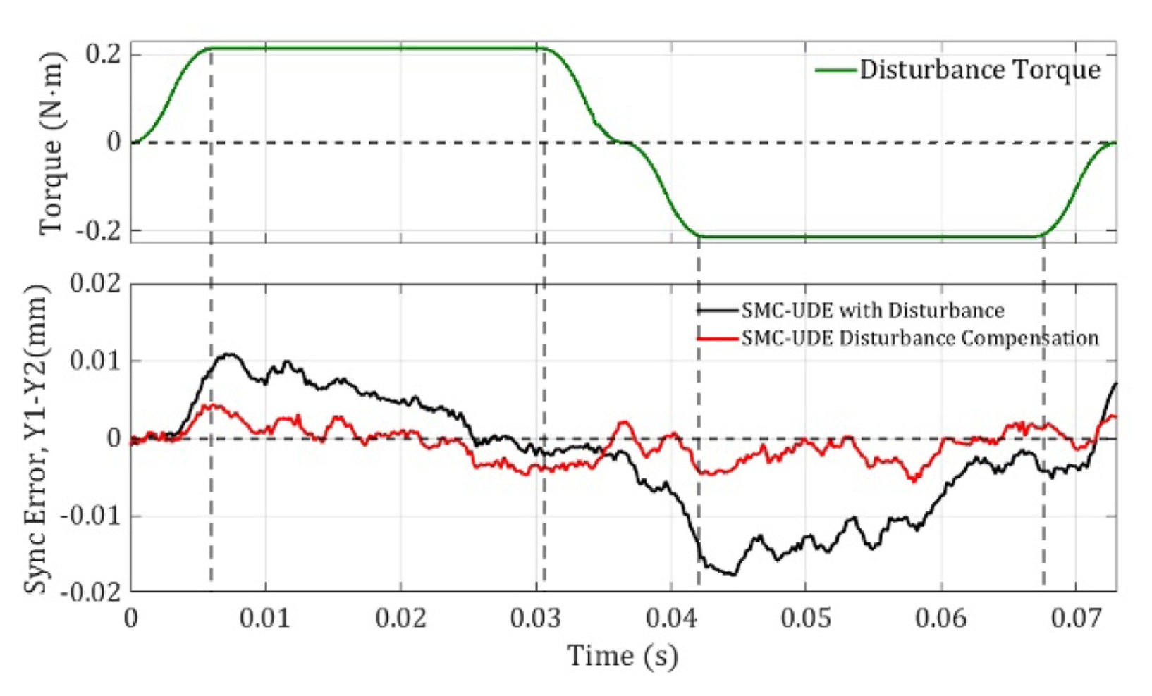
Fig. 6 presents the experimental results evaluating the effect of the torque disturbance, with the dual-drive motors at standstill. The upper plot shows the time-varying disturbance torque, where approximately ±0.2 N·m of torque was applied. The lower plot compares the synchronization error under the standstill condition with and without the application of the torque-disturbance compensation. In the case where only the disturbance is applied (black), an increase in synchronization error is observed. In contrast, applying the proposed compensation input (red) reduces the rms synchronization error from 7.5 to 1.7 μm, which yields about a 77.3% reduction under the same disturbance.
In order to analyze the effect of torque disturbance compensation, the synchronization errors during trajectory tracking control are compared with and without the torque disturbance. The stage follows an identical position trajectory as in
Fig. 5, and the torque disturbance is additionally generated by rotary motor on the payload.
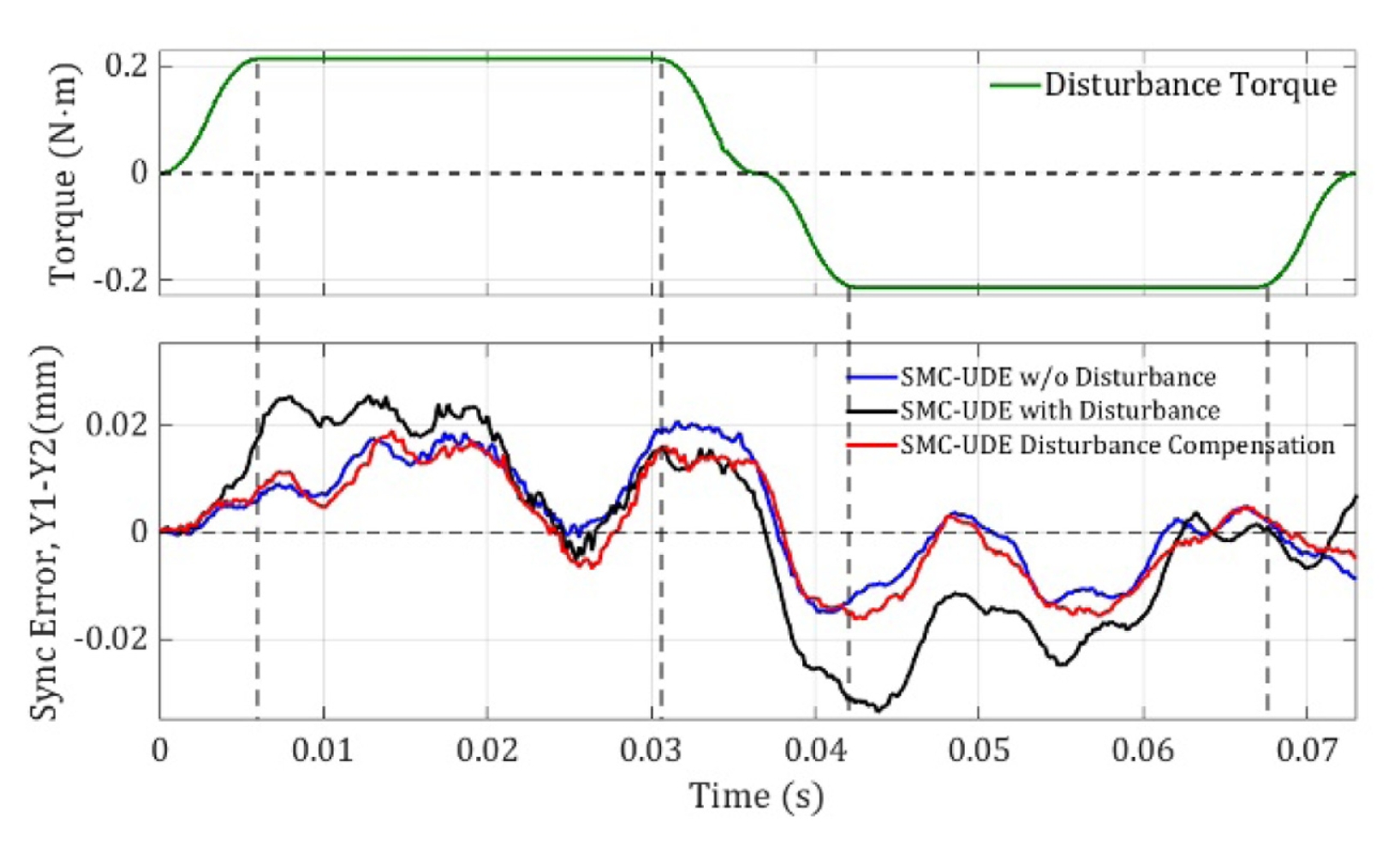
Fig. 7 presents experimental results analyzing the effect of the torque disturbance during the traveling command. The upper plot presents the torque disturbance, which is identical to that in
Fig. 6. The lower plot compares the synchronization error under three conditions during the same trajectory profile control. The blue line represents the case without disturbance, and the black line corresponds to the case in which the disturbance is applied without the torque compensation. Note that such a disturbance leads to an increase in the synchronization error. The red line represents the case in which the disturbance is applied, and the proposed torquedisturbance compensation is activated. In this case, the synchronization error remains close to the disturbance-free condition. The proposed compensation input reduces the RMS synchronization error from 16.5 to 9.8 μm, which corresponds to an improvement of approximately 40.6%.
Experiments under various torque disturbances with a maximum magnitude of 0.2 Nm were conducted to evaluate the robustness of the proposed method under different operating conditions. Specifically, a step disturbance and sinusoidal disturbances at 10 and 20 Hz were applied, and the results are compared with the conventional SMC-UDE approach. For all disturbance conditions, the proposed method reduced the peak synchronization error more than 50%, as shown in
Table 3. The experimental results confirm that the SMC-UDE controller achieves improved position tracking performance compared to the conventional master–master controller. However, the torque disturbance directly affects the synchronization error under both traveling and standstill conditions, which degrades the position control accuracy. Therefore, the rotational disturbances were effectively suppressed under both conditions through the proposed SMC-UDE controller with torque-disturbance compensation.
5. Conclusion
In this study, SMC-UDE controller with torque-disturbance compensation was proposed to reduce the synchronization error of an H-type gantry stage. By regulating both translation and rotation while actively canceling the torque disturbance, the overall controller provides enhanced synchronized motion, and the experimental results confirmed that the proposed method achieves a 76.7% reduction in settling time compared to the conventional master–master controller. In addition, the proposed controller maintained stable synchronization under torque disturbances during both traveling and standstill conditions, reducing the synchronization error by approximately 40.6% and 77.3%, respectively. These results confirm that the proposed control approach effectively suppresses rotational disturbances and improves synchronization robustness. The proposed method is expected to be applicable to high-throughput and precision multi-degree-of-freedom systems that require fast settling time and robust synchronized control.
FOOTNOTES
-
ACKNOWLEDGEMENT
This work was supported in part by the National Research Foundation of Korea (NRF) grant funded by the Korea government (MSIT) (No. RS-2023-00208437), and in part by Korea Planning & Evaluation Institute of Technology (KEIT) grant funded by the Korea government (MOTIE) (No. RS-2024-00441886).
Fig. 1Configuration of the H-type gantry stage Hardware-in-the-Loop (HIL) simulator. The hardware layer is implemented as a simplified stage designed to emulate the dynamics of the actual gantry system. The software layer includes the sliding mode controller (SMC) and the uncertainty and disturbance estimator (UDE), which can be applied to general gantry systems
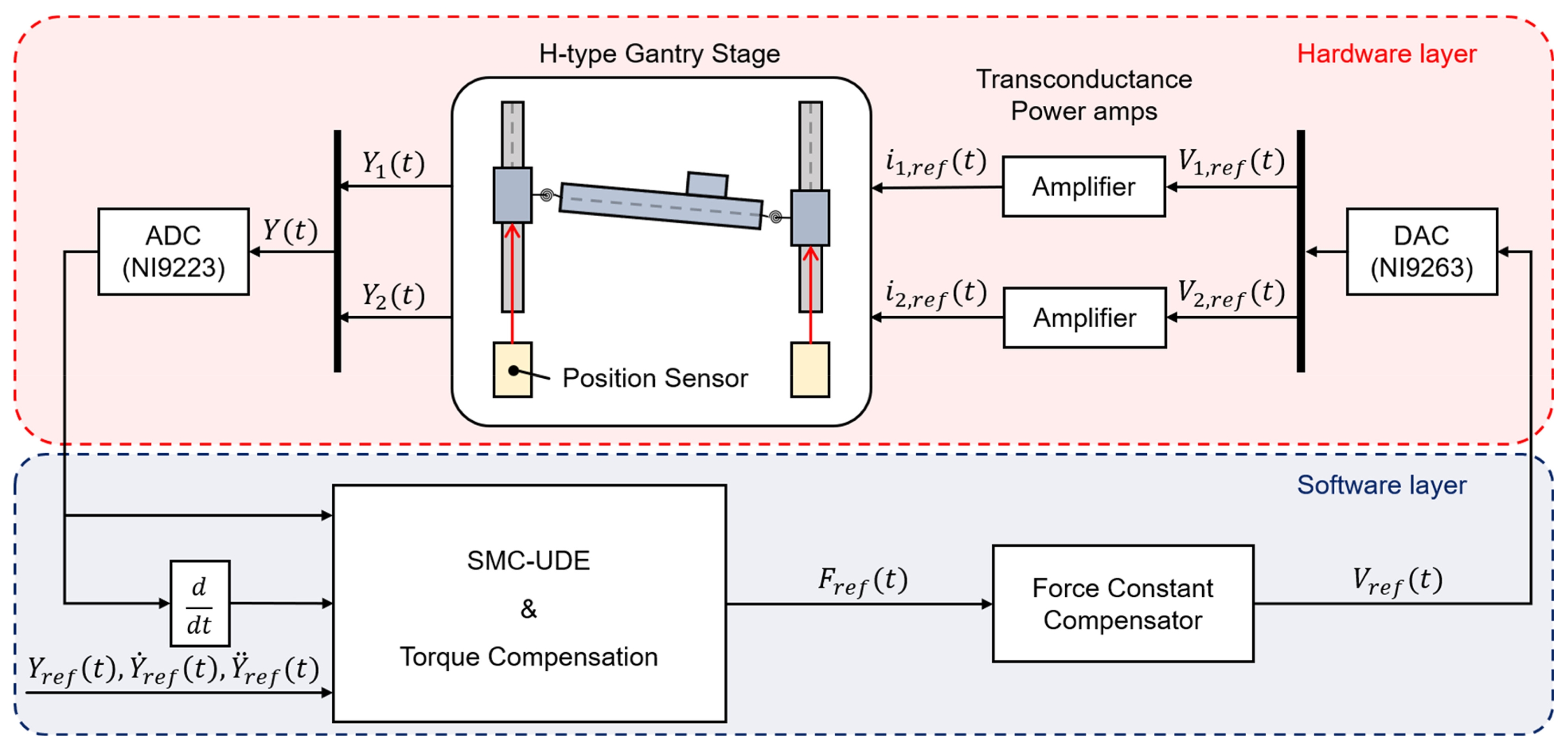
Fig. 2Experimental testbed for position control of the dual-drive VCM-based gantry stage. The two voice coil motors indicate the linear motors used in conventional gantry systems, and they are mechanically connected by a cross-arm. A payload equipped with a rotary motor that generates torque disturbance is installed on the cross-arm
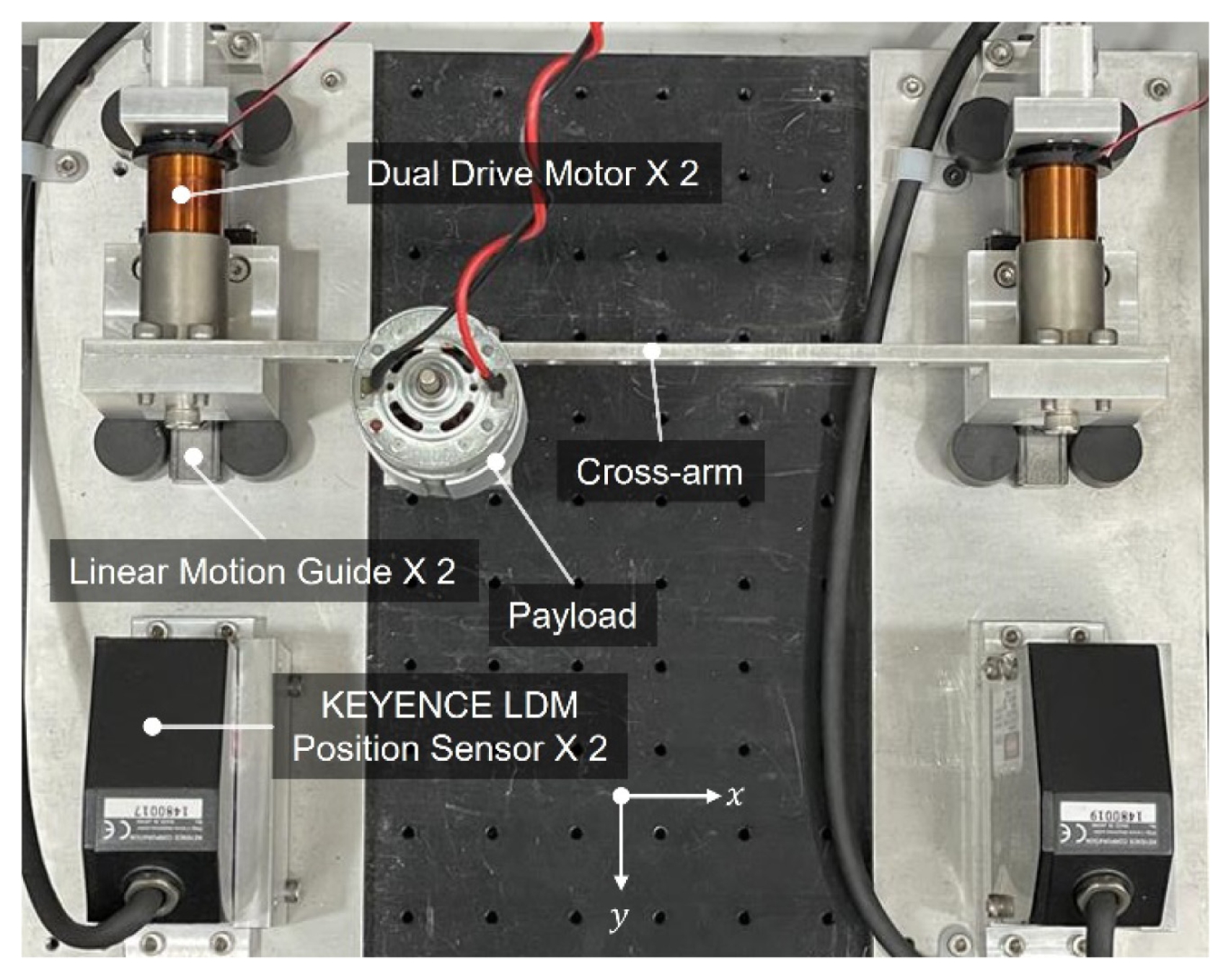
Fig. 3Equivalent model of the dual-drive VCM-based gantry stage. 2-DOF equivalent model of the VCM-based gantry stage composed of two direct-drive motors and a connecting cross-arm is illustrated. A payload (mh) is mounted on the cross-arm, and a torque disturbance is applied to the stage due to the rotational motion of the rotary motor attached to the cross-arm
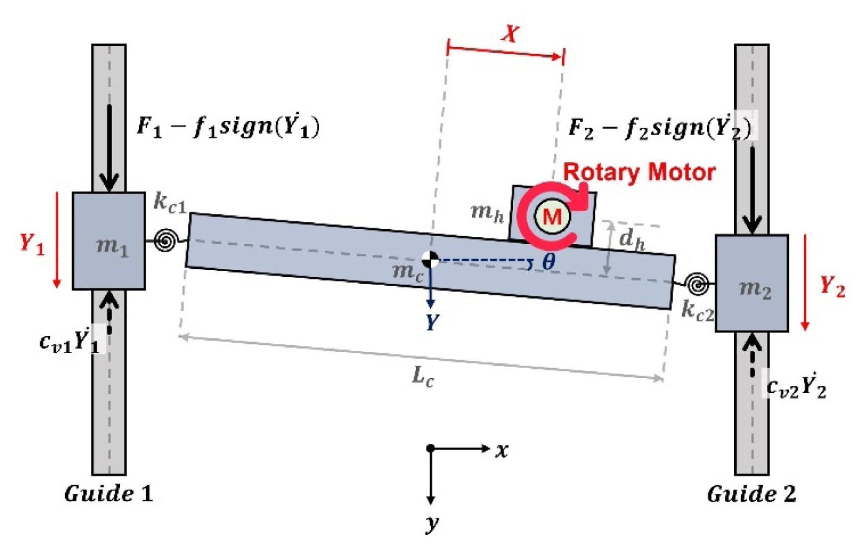
Fig. 4Block diagram of the SMC-UDE control loop with feedforward torque compensator for position control of the H-type gantry stage. The torque disturbance compensation path is activated to compensate for the torque disturbance generated by the rotational motion of the rotary motor attached to the payload
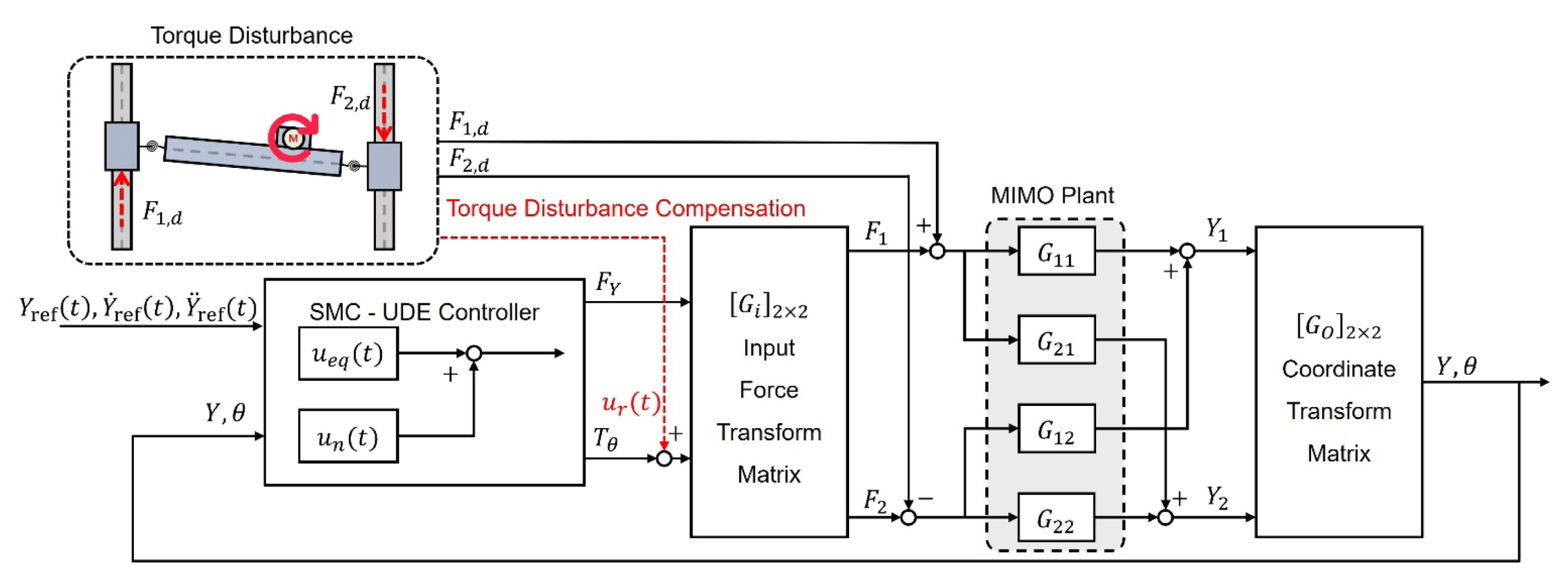
Fig. 5Experimental result of trajectory tracking control. After traveling, the settling time within 3 μm is observed. The conventional master–master control requires a settling time of 215.4 ms, while the SMC-UDE control achieves convergence within 50.2 ms. The lower plot illustrates the position response across the entire traveling range. The upper plot presents a magnified view of the settling phase
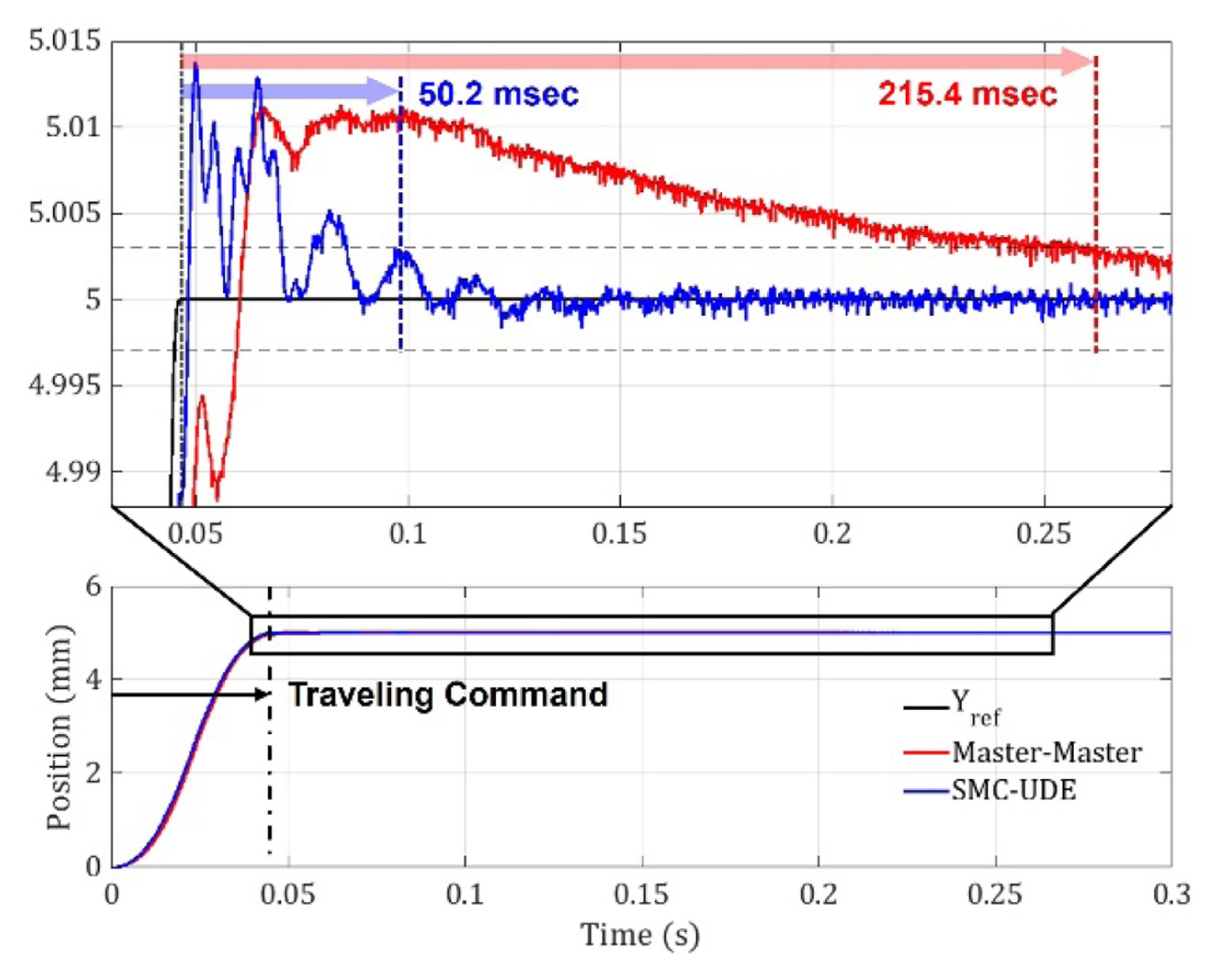
Fig. 6Comparison of synchronization error under torque disturbance in the dual-drive motor at standstill. Synchronization error without torque-disturbance compensation (black line) and with compensation (red line)
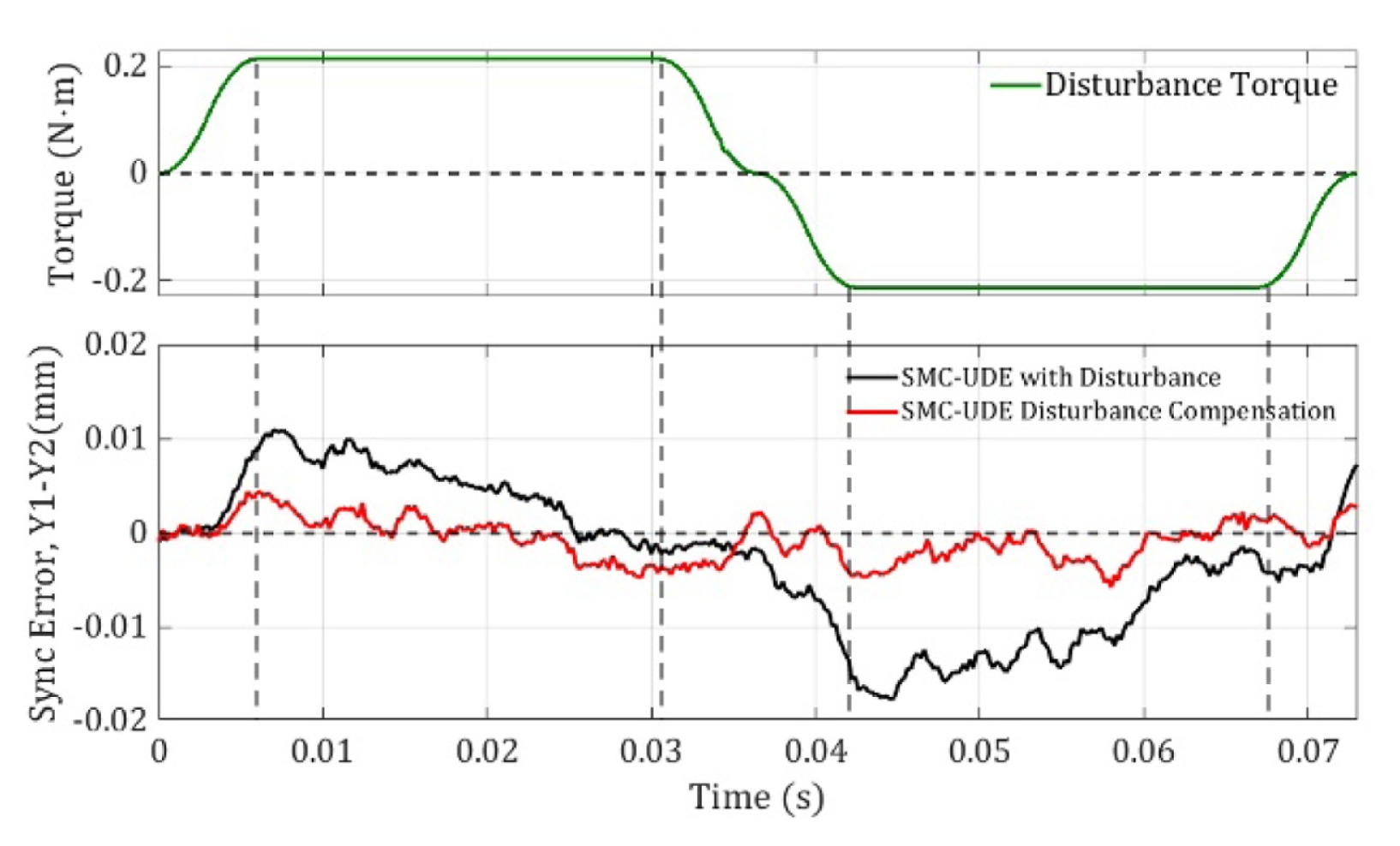
Fig. 7Experimental data comparing the SMC-UDE control performance under torque disturbance during the traveling command. The variation of synchronization error (Y1–Y2) with and without torque disturbance, as well as with disturbance compensation
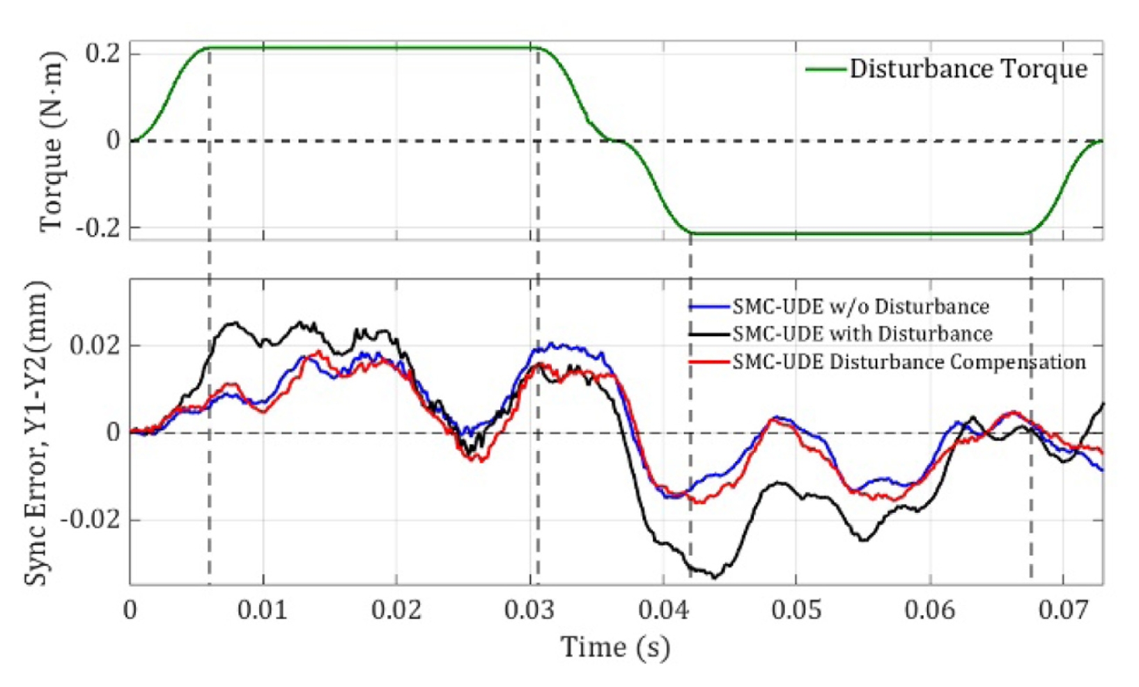
Table 1Parameters of the VCM-based gantry stage
Table 1
|
Name |
Value |
Description |
|
mc
|
36 g |
Mass of the cross-arm |
|
mh
|
385 g |
Mass of the payload |
|
m1
|
362.5 g |
Mass of VCM1 |
|
m2
|
362.5 g |
Mass of VCM2 |
|
cv1
|
9 N/(m/s) |
Viscous friction of Y1 axis |
|
cv2
|
11 N/(m/s) |
Viscous friction of Y2 axis |
|
f1
|
1.4 N |
Coulomb friction of Y1 axis |
|
f2
|
2.4 N |
Coulomb friction of Y2 axis |
|
kc
|
290 N·m/rad |
Stiffness of cross-arm (kc1, kc2) |
|
Lc
|
250 mm |
Length of the cross-arm |
|
dh
|
17.5 mm |
Distance between payload and cross-arm |
Table 2Parameters of the SMC-UDE controller
Table 2
|
Name |
Value |
Description |
|
λy
|
300 s−1
|
Sliding-surface gain for y-axis |
|
λθ
|
350 s−1
|
Sliding-surface gain for θ-axis |
|
ηy
|
200 s−1
|
Switching gain for y-axis |
|
ηθ
|
250 s−1
|
Switching gain for θ-axis |
|
τ
|
0.0032 s |
UDE filter time constant |
Table 3Experimental results of other disturbances
Table 3
|
Disturbances |
Sync error (w/o compensation) [mm] |
Sync error (w/ compensation) [mm] |
|
Step |
0.013 |
0.0061 |
|
10 Hz sine |
0.017 |
0.0045 |
|
20 Hz sine |
0.013 |
0.0038 |
REFERENCES
- 1. García-Herreros, I., Kestelyn, X., Gomand, J., Coleman, R., Barre, P., (2013), Model-based decoupling control method for dual-drive gantry stages: A case study with experimental validations, Control Engineering Practice, 21(3), 298-307.
- 2. Shi, P., Sun, W., Yang, X., Rudas, I. J., Gao, H., (2022), Master-slave synchronous control of dual-drive gantry stage with cogging force compensation, IEEE Transactions on Systems, Man, and Cybernetics: Systems, 53(1):216-225.
- 3. Sun, W., Liu, J., Gao, H., (2024), A composite high-speed and high-precision positioning approach for dual-drive gantry stage, IEEE Transactions on Automation Science and Engineering, 22, 2514-2525.
- 4. Li, C., Li, C., Chen, Z., Yao, B., (2018), Advanced synchronization control of a dual-linear-motor-driven gantry with rotational dynamics, IEEE Transactions on Industrial Electronics, 65(9), 7526-7535.
- 5. Li, D., Yoon, S. W., (2017), PCB assembly optimization in a single gantry high-speed rotary-head collect-and-place machine, The International Journal of Advanced Manufacturing Technology, 88(9), 2819-2834.
- 6. Mihalič, F., Truntič, M., Hren, A., (2022), Hardware-in-the-loop simulations: A historical overview of engineering challenges, Electronics, 11(15), 2462.
- 7. Sahu, G. N., Law, M., (2022), Hardware-in-the-loop simulator for emulation and active control of chatter, HardwareX, 11, e00273.
- 8. Millitzer, J., Mayer, D., Henke, C., Jersch, T., Tamm, C., Michael, J., Ranisch, C., (2018), Recent developments in hardware-in-the-loop testing, Model Validation and Uncertainty Quantification, Volume 3 Proceedings of the 36th IMAC, A Conference and Exposition on Structural Dynamics, Springer; Cham.
- 9. Fan, Y., He, Y., Zhang, D., Tan, U., (2018), Motion control of piezo-driven stage via a chattering-free sliding mode controller with hysteresis compensation, Proceedings of the IEEE/RSJ International Conference on Intelligent Robots and Systems. 6424-6430.
- 10. Londhe, P., Dhadekar, D. D., Patre, B., Waghmare, L., (2017), Uncertainty and disturbance estimator based sliding mode control of an autonomous underwater vehicle, International Journal of Dynamics and Control, 5(4), 1122-1138.
Biography
- Jung Ho Han
received the B.S degree in automotive engineering from Kookmin University, Seoul, South Korea, in 2024. He is currently working toward the M.S. degree in mobility systems engineering. at Yonsei University. His research interests include the control of electro- magnetic actuators for mechatronic systems and precision motion control.
- Sangmin Lee
received the B.S. degree in mechanical engineering from Yonsei University, Seoul, South Korea, in 2021. He is currently working toward the Ph.D. degree in mechanical engineering at Yonsei University. His research interests include manufacturing mechatronics, electromagnetic and electromechanical machine design, and precision motion control.
- Gi Hun Lee
received the B.S. degree in mechanical engineering from Yonsei University, Seoul, South Korea, in 2025. He is currently working toward the Ph.D. degree in mechanical engineering at Yonsei University, Seoul, South Korea. His research interests include design and precision motion control of mechatronic systems with electromagnetic actuators and power electronics.
- Hyo Geon Lee
received the B.S. degree in mechanical engineering from Yonsei University, Seoul, South Korea, in 2021, where he is currently pursuing the Ph.D. degree in mechanical engineering. His research interests include the design and analytic modeling of electromagnetic actuators, piezoelectric and electromagnetic precision stages, manufacturing mechatronic systems, biomedical and surgical robotic applications, sensor systems and fusion techniques, and control system design for precision motion control.
- Hong Sun Jang
received the B.S. degree in mechanical engineering from Yonsei University, Seoul, South Korea, in 2024. He is currently working toward the Ph.D. degree in mechanical engineering at Yonsei University. His research interests include design and precision motion control of mechatronic systems with electromagnetic actuators.
- Byung Wook Jeon
received the B.S. degree in mechanical engineering and electrical and electronic engineering from Yonsei University, Seoul, South Korea, in 2023. He is currently working toward the Ph.D. degree in mechanical engineering at Yonsei University. His research interests include design and precision motion control of mechatronic systems with electromagnetic actuators.
- Tae Sung Kim
received the B.S. degree in mechanical engineering from Yonsei University, Seoul, South Korea, in 2025. He is currently working toward the Ph.D. degree in mechanical engineering at Yonsei University. His research interests include the design and control of electromagnetic actuators for mechatronic systems and precision motion control.
- Hyeon Seok Im
received the B.S. degree in mechanical engineering from Yonsei University, Seoul, South Korea, in 2025. He is currently working toward the Ph.D. degree in mechanical engineering at Yonsei University. His research interests include the design and control of electromagnetic actuators for mechatronic systems and precision motion control.
- Jun Young Yoon
received the B.S. degree in mechanical engineering from Yonsei University, Seoul, South Korea, in 2009 and the M.S. and Ph.D. degrees in mechanical engineering from the Massachusetts Institute of Technology (MIT), Cambridge, MA, USA, in 2011 and 2017, respectively.
He is currently an Associate Professor at the Department of Mechanical Engineering, Yonsei University. From 2017 to 2019, he was a postdoctoral researcher in mechanical engineering and biological engineering at MIT. His research interests include manufacturing mechatronics and robotics system design, electromagnetic and electromechanical machine design, mechatronic devices for biomedical applications, and precision motion control.