ABSTRACT
The use of environmentally friendly, lubricant-free plastic seals in the rotating parts of robots and machines is on the rise. However, variations in seal geometry and operating conditions can influence the contact pressure between the seal and shaft, potentially leading to poor sealing performance, premature wear, or debris ingress. Therefore, advanced design optimization is essential. In this study, we conduct a parametric study and sensitivity analysis to enhance the performance of plastic seals. Finite element analysis (FEA) is carried out using a 2D axisymmetric model with interference fit contact conditions to accurately simulate the behavior of the seal and shaft. We verify the reliability of the analysis by comparing the deformation of the seal diameter before and after shaft insertion with experimental measurements obtained using a 3D tactile measurement device. We analyze four design variables: pressure, temperature, seal diameter, and coefficient of friction, considering seal contact pressure as the objective function. Sensitivity analysis is performed to determine the impact of these design variables on contact pressure and to identify trends.
-
KEYWORDS: Contact pressure, Finite element analysis, Parameter study, Plastic seal, Sensitivity analysis
-
KEYWORDS: 접촉 압력, 유한요소해석, 파라미터 스터디, 플라스틱 씰, 민감도 분석
1. 서론
일반적으로 로봇 혹은 기계의 회전체 부품 등에서 오일 씰(Seal)을 사용한다[
1,
2]. 오일 씰은 고정된 부품과 고속 회전하는 부품 사이의 틈을 유지하고 오일 누출을 방지하는 역할을 한다[
3,
4]. 그러나 오일(윤활유 등)을 사용하기 때문에 오일 씰 내구성에 문제가 있거나 씰과 샤프트의 연결이 불량할 경우 외부로 오일이 유출될 수 있는 경우가 있다[
5,
6]. 최근 오일 씰의 단점을 보완하기 위해 오일을 사용하지 않는 무윤활 방식의 플라스틱 씰이 주목받고 있다[
7]. 무윤활 플라스틱 씰은 별도의 윤활유를 사용하지 않고도 자체적으로 마찰 특성을 지니도록 설계된 씰이기 때문에 오일 공급 장치가 불필요하여 환경 친화적인 장점이 있다. 무윤활 플라스틱 씰의 소재는 주로 PTFE(테프론)이나 PEEK 등 고성능 플라스틱 소재가 쓰이며, 각 소재의 내열성·내화학성·내마모성 등을 활용해 다양한 산업 분야에서 적용된다[
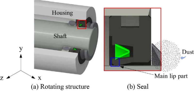
8]. 하지만 무윤활 플라스틱 씰은 윤활유를 사용하지 않기 때문에 씰이 샤프트에 가하는 압렵이 과도하게 클 경우 씰과 주변 부품의 마찰 및 마모가 가속화된다. 반대로 압력이 작을 경우
Fig. 1(b)와 같이 씰 외부로부터 이물질(Dust 등)이 유입될 가능성이 있다. 이러한 이유로 씰의 형상과 구동조건에 따라 압력 차이가 발생하는 문제가 있으며, 이는 고도화된 설계를 요구한다.
Fig. 1 Rotating body with a seal

선행 연구에서는 위의 단점을 보완하기 위한 다양한 연구가 진행되었다. Kim 등[
9]은 일반적인 씰에 사용되는 NBR (Nitrile Butadiene Rubber)의 배합 조성을 달리하여 씰의 탄성 회복율과 충진 입자의 크기 및 배합 상태 간의 상관관계를 분석하였으며, 충진 입자가 작을수록 밀봉 성능이 증가함을 보여주었다. 하지만 적정 밀봉 성능을 유지하기 위해 씰의 소재를 변경하는 방식이므로 씰의 구동 조건 및 형상을 변경하여 접촉 압력을 개선하고 있지 않다. Ilma 등[
10]은 씰의 밀봉력을 향상시키기 위해 씰에 삽입되어 있는 스프링의 탄성 특성을 최적화하고 디스크 스프링 구조 변경을 하여 밀봉력을 향상시켰다. Yoon 등[
11]은 2D 유한요소해석을 이용하여 간섭량, main lip의 각도 및 dust lip의 개수를 설계변수로 선정하여 파라미터 스터디를 수행하였으며, main lip의 각도가 작아질수록 응력이 증가하는 경향을 보여주었다.
그러나 앞선 연구들은 씰의 소재나 스프링 또는 형상만을 변경하여 밀봉력을 향상시켰다. 그리고 실제 구동 조건을 반영한 무윤활 플라스틱 씰의 접촉 압력 경향 연구는 아직 충분히 이루어지지 않은 실정이다.
따라서 본 논문에서는 무윤활 플라스틱 씰의 구동조건 및 형상 파라미터 스터디를 통한 씰이 샤프트에 가하는 압력 즉, 접촉 압력 경향을 연구하였다. 2D축대칭 조건과 억지끼움 접촉을 활용하여, 플라스틱 씰에 샤프트를 끼워 넣는 거동을 유한요소해석으로 구현하였다. 또한, 씰에 샤프트를 삽입하기 전과 후의 직경 변형량을 접촉식 3차원 측정기를 이용하여 측정하였으며, 해석 결과와 비교한 변형량의 차이를 확인하고, 이를 통해 해석 결과의 신뢰성을 입증하였다. 이후 무윤활 플라스틱 씰의 구동 및 형상에서 압력, 온도, 씰 직경 그리고 마찰계수를 설계변수로 설정하여 파라미터 스터디를 통한 민감도 분석을 진행하였다. 각 파라미터가 씰의 압력에 미치는 민감도를 분석하였고 이를 기반으로 구동조건과 형상에 따른 씰 접촉 압력의 경향을 연구하였다.
2. 플라스틱 씰의 2차원 해석
2.1 2D 모델링 구현을 위한 조건
본 연구에서 무윤활 플라스틱 씰은 크게 하우징, 샤프트, 플라스틱 씰 그리고 스프링으로 구성되어 있다. 여기서 스프링은 씰이 하우징과 샤프트에 안정적인 접촉하도록 돕는 역할을 한다. 이러한 조건을 유한요소해석 내에서도 반영하기 위해
Fig. 2(a)와 같이 스프링에 대한 모델링 이후 해석을 수행하였다. 실제 스프링의 길이가 2.82 mm이지만, 스프링이 끼워지는 씰 내부 스프링 삽입부의 크기는 2.70 mm이기 때문에 억지끼움에 따른 초기 Prestress 조건을 반영시켰다.
Fig. 2(b)를 통해 해석 결과를 확인할 수 있으며, 스프링은 0.1077 mm만큼 변형되었고, 이때 발생한 스프링의 반력은 33.84 N이다. 이를 바탕으로
Fig. 2(c)에서는 유한요소해석 소프트웨어 상으로 가상의 스프링을 추가하였으며, 이때 스프링은 Preload–free length 기능을 활용하여 억지끼움 조건을 모사하였다. 해석 결과를 통해 계산된 스프링 강성은 264.55 N/mm이다. 스프링의 재질은 SUS 316L이며, 자세한 스프링의 조건은
Table 1에 표기하였다.
Fig. 2Spring implementation in the analysis (a) initial spring model (b) result under press-fit condition (c) virtual spring element setup in FEM
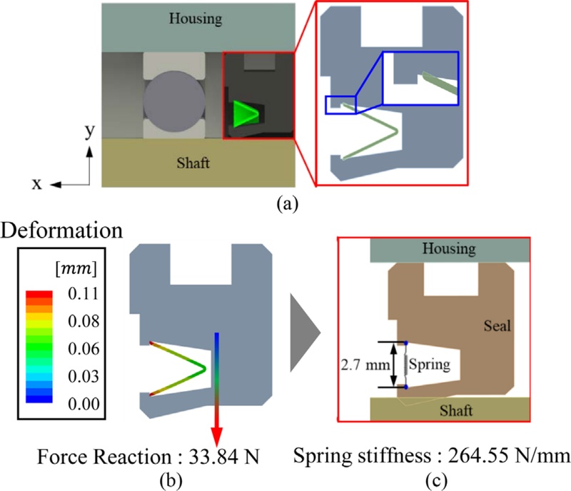
Table 1Condition of spring
Table 1
|
Definition |
Value |
|
Material |
SUS 316L |
|
Spring length [mm] |
2.70 |
|
Free length [mm] |
2.82 |
|
Deformation [mm] |
0.11 |
|
Force reaction [N] |
33.84 |
|
Longitudinal stiffness [N/mm] |
264.55 |
2.2 유한요소해석
2.2.1 재료의 기계적 성질
본 연구에 사용된 씰은 PTFE 소재로 제작하였다. 일반적으로 PTFE는 높은 내마모성을 가지고 있어 윤활제를 사용하지 않는 무윤활 플라스틱 씰에 적합하다. 따라서 무윤활 플라스틱 씰 소재 물성은 PTFE로 적용해 해석을 진행하였다. 또한 해석에 사용된 하우징 및 샤프트는 SUS 304를 사용하였고 세부 소재 특성은
Table 2에 제시한 바와 같이 사용하였다.
Table 2Material properties of seal
Table 2
|
Material properties |
PTFE |
Stainless 304
annealed |
|
Density [kg/m3] |
2,170 |
7,954 |
|
Young’s modulus [GPa] |
0.56 |
193.0 |
|
Poisson’s ratio [-] |
0.46 |
0.3 |
|
Ultimate tensile strength [MPa] |
12.38 |
252.1 |
|
Yield tensile strength [MPa] |
40.07 |
562.3 |
2.2.2 해석을 위한 경계조건 및 요소망 설정
본 연구에서는 무윤활 플라스틱 씰의 접촉 반력 개선을위해 전산 모사 방식을 채택하여, 유한요소 모델링 및 해석을 진행하였다.
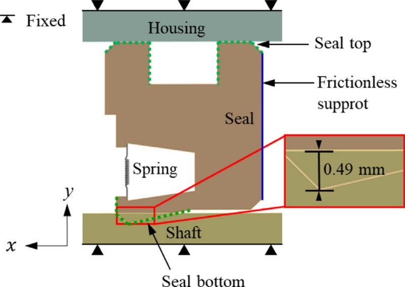
Fig. 3은 무윤활 플라스틱 씰에 대한 유한요소해석 모델링으로 씰의 주요 형상은 다음과 같다. 2D 축대칭 조건과 억지 끼움 접촉을 활용하여 유한요소해석 상에서 씰에 샤프트를 끼워 넣는 거동을 구현하였다. 먼저 하우징과 샤프트 그리고 씰에 대한 모든 면적에 22
oC의 균일 온도를 부여하였다. 또 경계조건으로는 하우징과 샤프트를 고정하였고 실제 씰의 내경과 샤프트의 지름을 측정 후 씰이 샤프트에 0.49 mm 겹치도록 억지 끼움 접촉을 주었으며 무윤활 조건에서 PTFE와 SUS 304 마찰계수는 0.3으로 고정하였다[
12]. Frictionless support를 씰의 우측 Edge 부분에 설정하여 y축 접선 방향으로 씰이 자유롭게 움직이도록 하였다. 씰의 상단부와 하우징 하단부 Edge를 Frictional로 두 표면 간의 마찰이 있는 접촉 상태 조건으로 설정하였다. 또 씰의 하단부와 샤프트 상단부 Edge는 동일 조건에서 Add offset, ramped effects를 설정하여 씰이 조여지기 전, 미세한 초기 간극을 추가하여 정상적으로 접촉이 형성되도록 하였다.
Fig. 3FE model of plastic seal
해석은 범용 해석 프로그램 ANSYS를 사용하였으며 해석 모델은 ANSYS spaceclaim [
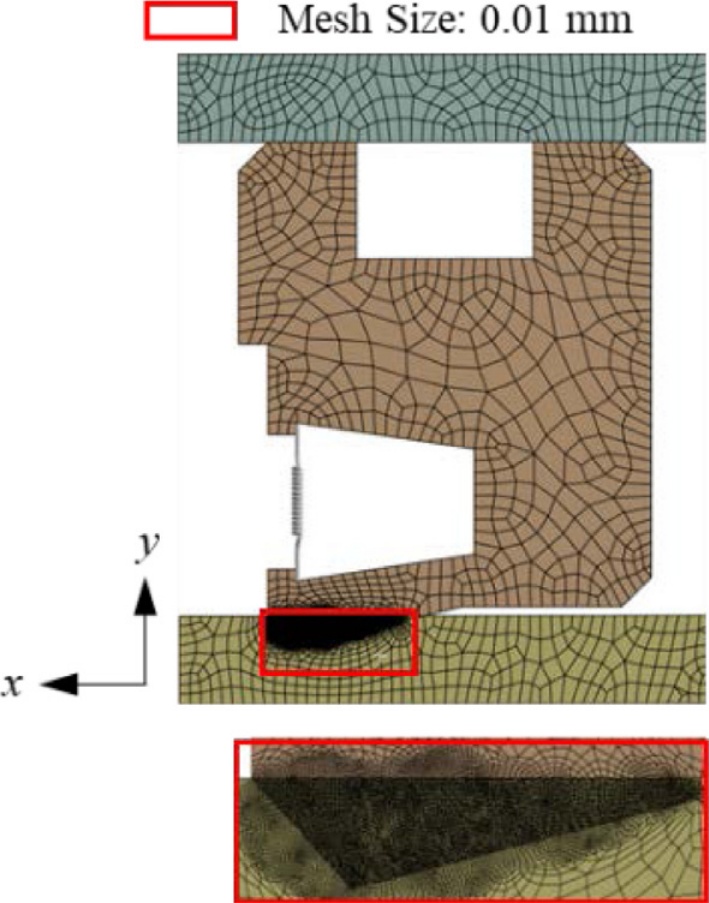
13]을 사용하여 제작하였다. Mesh 크기는
Fig. 4에 도시한 바와 같이 Main lip part와 샤프트에 과도 응력이 발생할 것으로 예상되어 구형 영역 지정을 통해 요소 망 크기를 0.01 mm로 설정하여 상대적으로 많은 요소를 배치하였다. 구성된 전체 모델은 절점이 40,460개, 요소가 13,179개이다.
Fig. 4Mesh size in the seal and interference fit area

2.3 유한요소해석 결과
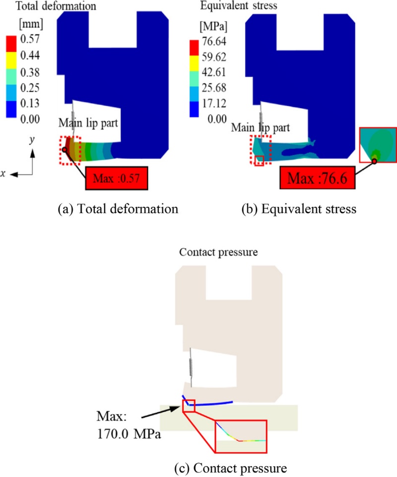
Figs. 5(a)-5(c)는 해석이 완료된 후 플라스틱 씰의 변형량, 응력 분포와 접촉 압력을 시각적으로 표현하였다. 해석 결과 씰의 Main lip part가
y 방향으로 상승함에 따라 씰의 최대 변형량은 Main lip part 좌측 부분에서 0.57 mm로 나타났다. 최대 응력은 Main lip part 하단 부분에서 76.6 MPa으로 확인되었으며, 접촉 압력은 Main lip part 하단 부분에서 170.0 MPa로 나타났다. 이때 등가 응력과 접촉 압력은 같은 단위를 사용하지만, 물리적 의미가 다르기 때문에 직접적인 수치 비교에는 한계가 있다.
Fig. 5FE results
2.4 실험 및 해석 결과를 통한 신뢰성 검증
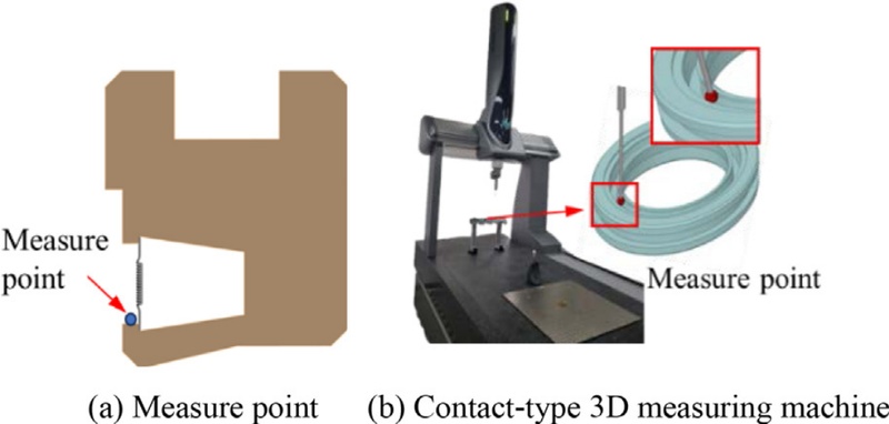
해석으로 도출된 결과의 신뢰성을 검증하고자 접촉식 3차원 측정기를 통해 씰과 샤프트 체결 전과 후 변형량을 확인하였다. 접촉식 3차원 측정기(Contact-type 3D measuring machine)는 프로브가 측정 대상 물체 표면에 물리적으로 접촉시켜 각 축(X, Y, Z)에 장착된 고정밀 스케일을 통해 프로브가 닿는 순간의 이동 거리를 3차원 좌표로 환산하는 장비이다. 접촉식 3차원 측정기 제원은
Table 3에 표기하였다. 실험 수행 과정은
Figs. 6(b)와 6(c)에 표시된 Measure point에 프로브를 접촉시켜 씰 면을 따라 360° 회전하여 씰의 직경 변화를 측정하였다. 플라스틱 씰과 샤프트 체결 전 측정 부위에서의 직경은 32.12 mm이고 체결 후 측정 부위에서의 직경은 32.67 mm로 나타났다. 따라서 샤프트 체결에 따른 씰의 측정 부위에서 직경 변형량은 0.55 mm이며
Fig. 6(a)에서 해석을 통해 구한 샤프트 체결에 따른 씰의 변형량은 0.57 mm으로 2.94%의 오차가 나타났다. 이를 통해 해석으로 확인한 씰의 변형량과 실험으로 확인한 씰의 변형량에 대한 신뢰성을 입증하였다.
Table 3Measurement results from a contact-type 3D measuring machine
Table 3
|
Manufacture (Model name) |
Hexagon (GLOBAL EVO 092008) |
|
Measurement range [mm] |
900 (x) × 1,600 (y) × 800 (z) |
|
Accuracy [μm] |
1.3-2 |
|
Drive system |
Direct drive method employing linear motors or servo motors |
Fig. 6Analysis and experimental measurement point of the plastic seal

Table 4Contact-type 3D measuring machine equipment specifications
Table 4
|
Unit [mm] |
Measurement |
|
Before shaft assembly |
32.1180 |
|
After shaft assembly |
32.6683 |
|
Deformation |
0.5503 |
3. 파라미터 스터디 및 민감도 분석
3.1 플라스틱 씰의 해석 절차
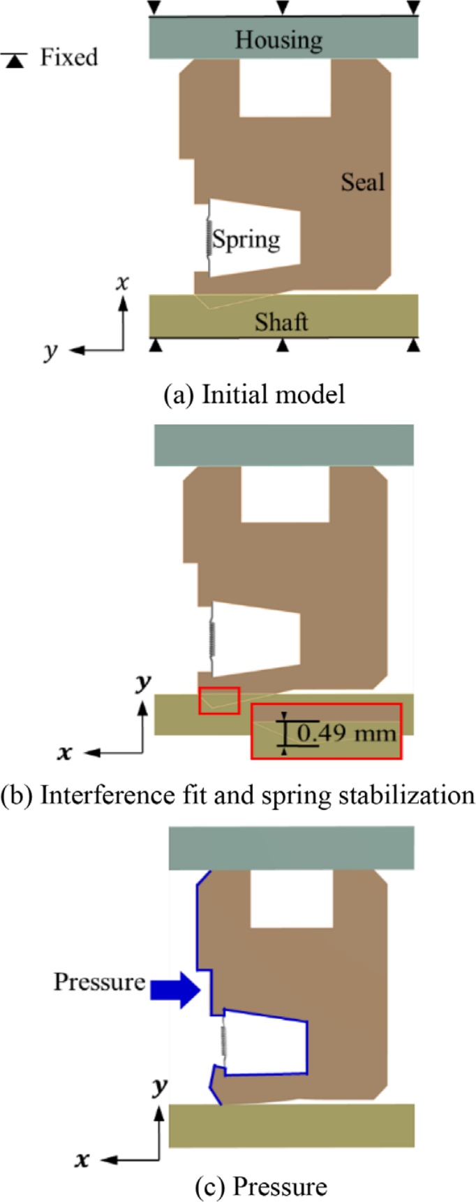
Fig. 7은 무윤활 플라스틱 씰의 해석 수행 순서이다. 먼저 해석에 적용된 모델은
Figs. 7(a)로 이전 모델과 동일하며, 실제 실험 상에서 씰의 구동은 샤프트를 결합할 때 샤프트는
y 방향으로 이동하며 결합되므로
7(b)와 같이 해석 상에서 씰의 구동은 샤프트에 억지끼움 조건으로 접촉이 되도록 하였다. 씰과 샤프트 사이에서의 마찰계수는 0.3으로 고정하였다. 이후
Fig. 7(c)와 같이 씰의 좌측 면 (-
y)방향으로 실제 씰을 사용하는 환경과 유사하게 묘사하기 위해 1초 후에 압력이 가해지도록 설정하였다.
Fig. 7Analysis procedure of the plastic seal
3.2 파라미터 스터디 해석 조건 설정 및 결과
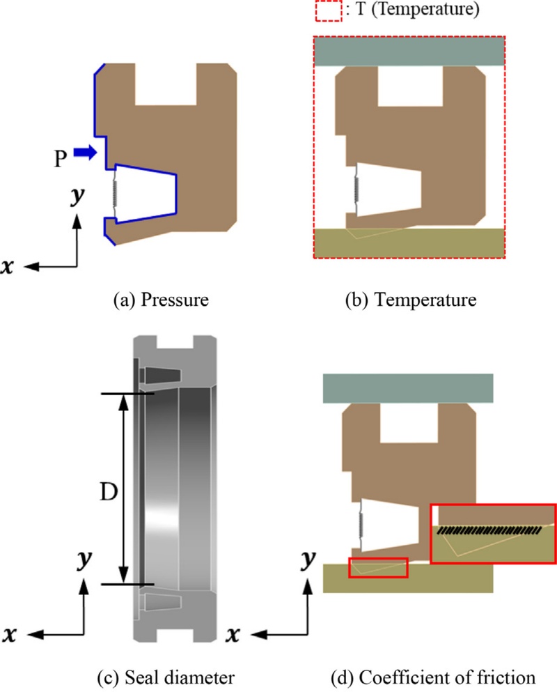
무윤활 플라스틱 씰의 압력을 측정하여, 씰에 미치는 영향을 파악할 수 있다. 무윤활 플라스틱 씰의 접촉 반력이 적정량에 미치지 못하면, 외부로부터 이물질 및 오염이 유입되어 내부 부품의 손상 및 수명 단축을 유발할 수 있다. 반대로 무윤활 플라스틱 씰의 접촉 반력이 적정량을 초과하면, 씰과 주변 부품의 마찰 및 마모가 가속화되어 씰의 마모 또는 손상이 발생한다. 또한, 씰이 과도하게 눌리거나 찌그러지는 변형이 발생할 수 있다. 따라서 무윤활 플라스틱 씰이 적정량의 압력을 적용 받을 수 있도록 하는 씰의 구동조건 및 형상에 따른 설계변수를 지정하고자 한다. 플라스틱 씰의 주요 요소는
Fig. 8에 도시하였다. 4가지의 설계변수가 압력을 개선하기 위해 조정되었으며, 각각 씰 압력(P), 씰 온도(T), 씰 직경(D) 그리고 마찰계수(μ)이다. 여기서 마찰계수(μ)는 PTFE와 SUS 304 마찰 조건에서 마찰계수가 0.1-0.3에 분포한다는 선행 논문을 참고하여 설정하였다[
12,
14]. 설계변수의 최대와 최소값 범위는
Table 5에 정리하였다.
Fig. 8Design variables of plastic seal

Table 5Range of seal design variables
Table 5
|
Design variables |
Minimum |
Maximum |
|
Pressure [MPa] |
0.1 |
0.5 |
|
Temperature [oC] |
25.0 |
75.0 |
|
Diameter [mm] |
29.6 |
29.7 |
|
Coefficient of friction [-] |
0.1 |
0.3 |
민감도 분석(Sensitivity analysis)은 설정된 설계 변수가 변화함에 따라 목적 함수에 미치는 영향을 평가하는 방법이다[
15]. 이를 활용하여 각 설계 변수의 영향력을 정량적으로 파악할 수 있으며, 변수의 값이 클수록 목적 함수에 미치는 영향 또한 증가함을 의미한다. 실험점은 실험계획법을 통해 지정하였으며, 4요소 2수준 Full-factorial로 설계하여 총 16번의 해석을 진행하였다. 경계조건과 Mesh의 크기는 이전 해석과 동일하게 설정하였다.
파라미터 스터디 결과는
Table 6, 민감도 분석 결과는
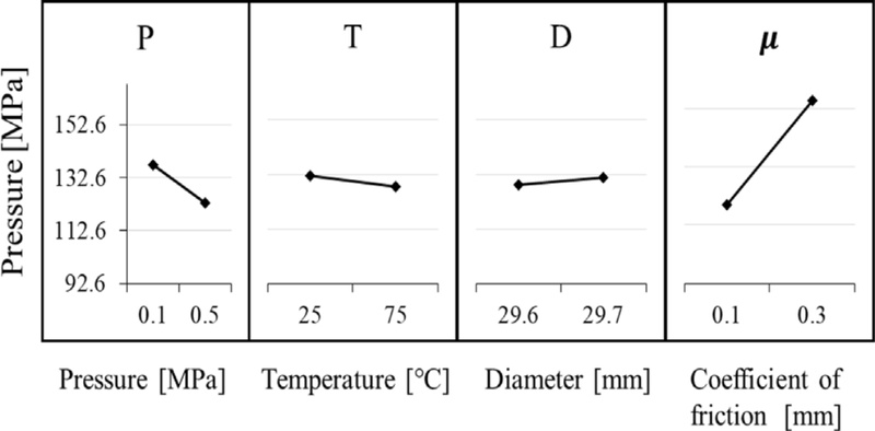
Fig. 9와 같으며,
Table 7은 분석 결과를 표로 정리하였다.
Table 6에서 분석결과 P는 0.1 MPa, T는 25.0
oC, D는 29.7 mm, μ는 0.3일 때 접촉 압력은 169.3 MPa로 가장 높은 접촉 압력이 나타났다.
Fig. 9에서 설계변수 값이 증가함에 따라 P, T는 접촉압력이 낮아지는 음의 상관관계, D, μ는 접촉압력이 증가하는 양의 상관관계로 나타났다.
Table 7에서의 민감도 결과는 마찰계수가 72.1%로 가장 높은 민감도를 보였으며, 그 다음으로 압력과 온도가 가장 높은 순으로 나타났다.
Table 6Analysis of the seal parameter study
Table 6
|
Design variables |
Objective functions |
|
No. |
P
[MPa] |
T
[oC] |
D
[mm] |
μ
[-] |
Contact pressure
[MPa] |
|
1 |
0.1 |
25.0 |
29.6 |
0.1 |
110.7 |
|
2 |
0.5 |
25.0 |
29.6 |
0.1 |
97.9 |
|
3 |
0.1 |
75.0 |
29.6 |
0.1 |
107.0 |
|
4 |
0.5 |
75.0 |
29.6 |
0.1 |
94.6 |
|
5 |
0.1 |
25.0 |
29.7 |
0.1 |
112.5 |
|
6 |
0.5 |
25.0 |
29.7 |
0.1 |
99.3 |
|
7 |
0.1 |
75.0 |
29.7 |
0.1 |
108.8 |
|
8 |
0.5 |
75.0 |
29.7 |
0.1 |
95.9 |
|
9 |
0.1 |
25.0 |
29.6 |
0.3 |
165.2 |
|
10 |
0.5 |
25.0 |
29.6 |
0.3 |
149.6 |
|
11 |
0.1 |
75.0 |
29.6 |
0.3 |
160.5 |
|
12 |
0.5 |
75.0 |
29.6 |
0.3 |
145.6 |
|
13 |
0.1 |
25.0 |
29.7 |
0.3 |
169.3 |
|
14 |
0.5 |
25.0 |
29.7 |
0.3 |
153.2 |
|
15 |
0.1 |
75.0 |
29.7 |
0.3 |
164.3 |
|
16 |
0.5 |
75.0 |
29.7 |
0.3 |
148.8 |
Fig. 9.Sensitivity analysis results

Table 7Contact pressure and sensitivity analysis results
Table 7
|
Level |
P |
T |
D |
μ |
|
1 [MPa] |
137.3 |
132.2 |
128.9 |
103.3 |
|
2 [MPa] |
123.1 |
128.19 |
131.5 |
157.1 |
|
Delta [MPa] |
14.2 |
4.0 |
2.6 |
53.7 |
|
Share [%] |
19.0 |
5.3 |
3.5 |
72.1 |
|
Rank [-] |
2 |
3 |
4 |
1 |
4. 결론
본 연구는 무윤활 방식 씰의 접촉 압력을 개선하기 위해 유한요소해석과 이를 검증하는 실험을 수행하였다. 또한 압력에 대한 주요 파라미터를 설정하여 파라미터 스터디와 그에 따른 민감도를 분석하였고, 이를 기반으로 접촉 압력 경향을 연구하였다. 그 결과는 다음과 같다.
(1) 무윤활 방식의 플라스틱 씰에 대하여 2D 축대칭 조건과 억지 끼움 접촉을 활용하여 유한요소해석 상에서 씰에 샤프트를 끼워 넣는 거동을 구현하였다.
(2) 접촉식 3차원 측정기를 통해 플라스틱 씰과 샤프트의 변형량을 확인하였으며 해당 변형량은 0.55 mm로 해석과 2.94%의 차이로 유사한 거동이 나타나는 것을 확인하였다.
(3) 플라스틱 씰의 구동 및 형상에서 온도, 압력과 씰 내경 길이를 설계변수로 설정하여 파라미터 스터디를 통한 유한요소해석을 진행하였다. 각 파라미터가 씰에 미치는 민감도를 분석하였다.
(4) 씰의 접촉 압력을 개선하고자 4가지 설계변수(씰 압력(P), 씰 온도(T), 씰 직경(D), 그리고 마찰계수(μ)에 대한 민감도 분석을 수행하였다. 그 결과 접촉 압력에 가장 큰 영향을 미치는 변수는 마찰계수(μ), 씰 압력(P), 씰 온도(T) 그리고 씰 직경(D) 순으로 높게 나타났다.
본 논문에서는 유한요소해석 과정에서 2D 축대칭 조건과 억지 끼움 접촉을 활용하여 파라미터 스터디를 통한 씰 압력에 대한 민감도를 파악할 수 있었다. 그러나 본 연구는 2D 축대칭을 활용하여 씰을 샤프트에 끼운 정적 상태에 대한 해석을 수행하였기 때문에 실제 샤프트 회전 조건을 포함한 동적 상태의 해석은 포함되어 있지 않다. 향후 발전된 연구에서는 샤프트의 회전 조건을 포함한 3D 해석을 수행하고, 최적화를 진행하고자 한다.
ACKNOWLEDGMENTS
이 논문은 서울시 산학연 협력사업 2024년 첨단제조 기술사업화 지원사업(No. HM24004)의 지원을 받아 수행된 연구임.
REFERENCES
- 1.
Kim, H. C., (2023), The study of predictive diagnosis technology development status and promotion plan for reactor coolant pump, Transactions of the Korean Society of Pressure Vessels and Piping, 19(1), 44-51.
- 2.
Choi, S., Kim, J., Lee, S., Jeong, D., (2024), Durability test design of hydraulic gear pump for agricultural tractors, Journal of Mechanical Science and Technology, 48(4), 279-284.
10.3795/KSME-A.2024.48.4.279
- 3.
Je, Y., Kim, H., Kim, L., Chung, K., An, J., Jeon, H., (2014) Component and bench tests of polyurethane hydraulic reciprocating seal for accelerated life testing, Journal of the Korean Society of Tribologists & Lubrication Engineers, 30(5), 271-277.
10.9725/kstle.2014.30.5.271
- 4.
Kim, T., Jang, G., (2016), Research trends in rotor dynamics and tribological elements in 2015, The KSFM Journal of Fluid Machinery, 19(2), 67-70.
10.5293/kfma.2016.19.2.067
- 5.
Cha, J., Shin, M., (2022), A study on improvement of oil leakage by applying double seals in the hydraulic fan motor for K200 series tracked vehicles, Journal of the Korea Academia-Industrial Cooperation Society, 23(5), 32-39.
10.5762/KAIS.2022.23.5.32
- 6.
Hwang, J., Kim, C., (2017), Optimum design of cross section lateral damper oil seals for high speed railway vehicle, Journal of the Korea Academia-Industrial, 18(1), 597-584.
10.5762/KAIS.2017.18.1.579
- 7.
Bang, H., Park, J., Choi, J., An, S., Rhee, H., (2022), Reliability study on life guarantee of a rotary union seal Unit for CMP, Journal of the Korean Society of Mechanical Engineers, 46(12), 1057-1062.
10.3795/KSME-A.2022.46.12.1057
- 8.
Nunes, L., Dias, F., da Costa Mattos, H., (2011), Mechanical behavior of polytetrafluoroethylene in tensile loading under different strain rates, Polymer Testing, 30(7), 791-796.
10.1016/j.polymertesting.2011.07.004
- 9.
Kim, T., (2015), A study on sealing performance of elastomeric rotary lip seals for washing machines, Journal of the Korean Society of Tribologists & Lubrication Engineers, 31(3), 102-108.
10.9725/kstle.2015.31.3.102
- 10.
Hasanov, I. I., Guliyev, A. A., (2023), Development of effective sealing units for oil and gas equipment in the oil and gas production system, Nafta-Gaz, 79(7), 464-472.
10.18668/NG.2023.07.03
- 11.
Yoon, H., Jeon, G., Choi, J., (2019), A Study on the design of transmission oil-seal using 2D finite element analysis, Journal of the Korean Society of Manufacturing Process Engineers, 18(1), 85-93.
10.14775/ksmpe.2019.18.1.085
- 12.
Dong, S., Chung, K.-H., Lee, K.-S., (2011), Effect of surface roughness of counterface on tribological characteristics of ptfe and uhmwpe, Tribology and Lubricants, 27(6), 293-301.
10.9725/kstle.2011.27.6.293
- 13.
- 14.
Unal, H., Yetgin, S. H., Mimaroglu, A., Sumer, M., (2010), The effect of test parameters on friction and wear performance of PTFE and PTFE composites, Journal of Reinforced Plastics and Composites, 29(13), 1978-1986.
10.1177/0731684409340708
- 15.
Hwang, S., Oh, M., Sul, O., Yoo, M., Chung, Y., Hong, S., (2023), Design of a lightweight model for the battery carrier of a commercial large electric truck using the response surface method, Journal of the Korean Society of Manufacturing Technology Engineers, 32(5), 283-288.
10.7735/ksmte.2023.32.5.283
Biography
- Hyeong Jun Shim
M. S. candidate in the Department of Future Convergence Engineering, Kongju National University. His research interest is FEA
- Min Seong Oh
M. S. candidate in the Department of Future Convergence Engineering, Kongju National University. His research interest is FEA
- Su Bong An
B. S. candidate in the Department of Marine Electro-mechanical Engineering, National Korea Maritime & Ocean University. His research interest is Seal wear mechanism.
- Hee Jang Rhee
M. S. Sealink Corp. CEO. His research interest is Seal wear mechanism.
- Seok Moo Hong
Professor in the Department of Future Automotive Engineering, Kongju National University. His research interest is Metal Sheet Forming and Forging, FEA, Optimizing.