ABSTRACT
In this study, we developed a composite anode support composed of La-doped SrTiO3 (LST) and Gd-doped CeO2 (GDC) using a tape casting process for solid oxide fuel cells (SOFCs). By adjusting the pore former content in the slurry, we constructed a bilayered structure consisting of a porous anode support layer (ASL) and a dense anode functional layer (AFL) with the same material composition. The number of tape-cast sheets was controlled to tailor the overall thickness, and lamination followed by co-sintering at 1250oC resulted in a mechanically robust bilayer. We characterized the microstructural evolution concerning sintering temperature and pore former content using SEM, while XRD confirmed the phase stability of LST and GDC. The measured electrical conductivity at 750oC ensured sufficient electron transport. To enhance interfacial adhesion and suppress secondary phase formation, we introduced a GDC buffer layer and a pre-sintering treatment prior to electrolyte deposition. A full cell with a YSZ electrolyte and LSCF cathode achieved a stable open circuit voltage of approximately 0.7 V and demonstrated continuous operation at 750oC. These findings highlight the suitability of LST-GDC composite anodes as thermochemically stable supports, potentially enabling direct hydrocarbon utilization in intermediate-temperature SOFCs.
-
KEYWORDS: Solid oxide fuel cell, LST-GDC composite, Tape casting, Anode-supported, Microstructure
-
KEYWORDS: 고체산화물연료전지, LST-GDC 복합체, 테이프캐스팅, 연료극 지지체, 미세구조
1. 서론
연료전지는 수소와 산소의 전기화학반응을 통해 화학에너지를 직접 전기에너지로 변환하는 에너지 변환 장치로, 무공해·저소음의 특징을 가지며 탄소중립 시대에 주목받는 친환경 에너지원이다
[1,
2]. 다양한 연료와 크기 유연성을 바탕으로 수소뿐 아니라 바이오가스, 천연가스 등 다양한 가스를 연료로 사용할 수 있다는 장점이 있다
[3,
4]. 연료전지는 연료극, 전해질, 공기극으로 구성되며, 고체산화물 연료전지(Solid Oxide Fuel Cell, SOFC)는 세라믹 기반의 고체산화물을 전해질로 사용한다. 고체 전해질의 이온 전도 특성 때문에 일반적으로 700-1000
oC의 높은 작동 온도가 요구되며
[5], 전해질 두께가 얇을수록 이온 저항이 낮아져 높은 성능 구현이 가능하다. 이에 따라, 최근에는 전해질을 얇게 구현할 수 있는 연료극 지지체 구조에 대한 연구가 활발히 진행되고 있으며
[6,
7], 이 구조에서는 연료극 소재의 전기적·기계적 특성이 매우 중요하다. 가장 널리 사용되는 연료극 재료인 NiO-YSZ는 높은 전기전도도와 촉매 활성을 바탕으로 우수한 초기 성능을 보이나, 고온 작동 중 Ni 입자의 조대화
[8]로 Triple Phase Boundary (TPB)가 감소하며 장기 내구성이 저하되는 한계가 있다
[9,
10]. 특히 메탄과 같은 탄화수소 기반 연료 사용 시, Coke Formation
[11-
13]과 Sulfur Poisoning
[5,
14-
16]이 발생하여 반응 면적이 줄어들고 결국 연료전지 성능 저하로 이어진다. 이러한 문제를 극복하기 위해, Ni-free 기반의 새로운 연료극 소재 개발(Cu-CeO2
[17], Zr-CeO2
[18]와 doped-LaCrO3
[19] 등)이 활발히 이루어지고 있다
[20].
그중 하나인 La가 도핑된 SrTiO
3 (LST) 기반 페로브스카이트 물질
[21-
23]은 YSZ 전해질과 유사한 열팽창 계수, 안정한 구조, 높은 내산화환원성, 그리고 Coke·Sulfur 내성을 가지는 장점이 있다
[21,
22]. 금속 촉매 없이도 장기간 안정한 작동이 가능하다는 측면에서 주목받고 있으나, 단독 사용 시 낮은 전기전도도와 부족한 촉매 활성으로 인해 전기화학적 성능이 제한되는 단점이 존재한다. 이를 보완하기 위해 Mixed Ionic-electronic Conductors (MIEC)인 Gd-doped CeO₂ (GDC)를 혼합한 LST-GDC 복합 전극이 제안되었으며, 성능 향상 및 내구성 확보 측면에서 유망한 소재 조합으로 보고되고 있다
[24,
25]. GDC는 표면에 풍부한 산소 공공을 제공하여 연료극의 산화 반응의 촉매 활성을 증가시킨다. 전극 내부에 산소 이온 전도 경로가 형성되어 TPB를 확장할 수 있다. 이렇게 반응 면적을 확장시켜 전극-전해질 계면에서의 분극 저항을 효과적으로 감소시킬 수 있다
[26,
27]. 하지만, 기존의 LST-GDC 연료극 연구들은 대부분 전해질 지지체 혹은 전해질 Pellet 위에 Paste 형태로 도포하는 방식으로 제작되어 왔다. 이러한 구조적 한계로 인해 전해질을 얇게 형성하는 것이 어렵고
[24,
28], 필연적으로 두꺼운 전해질층에 의해 Ohmic Loss가 크게 발생하게 된다. 결과적으로 연료전지의 전체 성능 향상에 근본적인 제약이 존재한다.
따라서 본 연구에서는 이러한 한계를 극복하고자 Tape-casting 공정을 활용하여 LST-GDC 기반 연료극 지지체 구조를 제작하였다. 이 구조는 기계적 지지력을 연료극이 담당함으로써 전해질층을 수 마이크론 두께로 얇게 구현할 수 있으며
[29], 이를 통해 Ohmic 저항을 줄이고 연료전지의 전기화학적 성능을 효과적으로 향상시킬 수 있다
2. 실험
2.1 LST-GDC 연료극 지지체 제작
본 연구에서는 LST와 GDC가 혼합된 연료극 지지체를 제작하기 위하여 Tape-casting 공정을 적용하였다. LST와 GDC 분말은 1 : 1 (Weight Ratio)로 혼합하였고, 이를 기반으로 슬러리를 제조하였다. 슬러리의 Solvent로는 Ethanol과 Toluene을 사용하였으며, Dispersant로는 KD1, 바인더로는 Polyvinyl Butyral (PVB), Plasticizer로는 Dibutyl Phthalate (DBP)를 첨가하였다. 또한, Pore Former로 Polymethyl Methacrylate (PMMA)를 사용하였으며, 그 첨가량(wt%)을 조절하여 연료극의 Porosity를 제어하였다. 제작된 Slurry는 Powder 양에 비례한 양의 지르코니아 볼과 함께 135 rpm으로 24시간 동안 Ball Milling 하여 균일하게 혼합하였고, 이후 볼을 제거한 뒤 추가적인 Degassing을 위한 Ball Milling을 실시하였다. 완성된 슬러리는 Doctor Blade 간격을 5 μm, Casting 속도를 5 cm/min으로 설정하여 Tape-casting하였으며, 이후 80oC에서 12시간 동안 건조하여 sheet를 형성하였다.
지지체 형성을 위하여 건조된 Sheet를 70oC, 20 MPa의 조건에서 20분간 열압착(Lamination)하였다. Anode Support Layer (ASL)는 PMMA가 포함된 Sheet 6장을 적층하여 구성하였으며, Anode Functional Layer (AFL)는 PMMA가 포함되지 않은 Sheet 1장으로 구성하였다. 적층된 Tape은 공기 분위기에서 1150, 1250, 1350, 1450oC로 소결하였으며, 소결 시 기판의 휨 현상을 방지하기 위해 Pre-sintering 후 Main Sintering을 진행하였다.
2.2 LST-GDC 연료극 지지체 특성 평가 및 전기화학평가
연료극 지지체의 미세구조는 주사전자현미경(SEM)을 이용하여 분석하였으며, LST와 GDC의 상 변화 및 반응 여부는 X-선회절 분석(XRD)을 통해 확인하였다. 적층 및 소결(1450oC, Air)된 시편의 표면에 Platinum 전극을 스퍼터링으로 증착한 후, 500-750oC의 온도 범위에서 In-plane 방식으로 전기전도도를 측정하였다.
고체산화물 연료전지(SOFC)로서의 성능을 확인하기 위하여 GDC Buffer Layer, YSZ 전해질층, LSCF 공기극을 순차적으로 스크린프린팅하여 증착하였으며, 각 층은 개별적으로 소결하였다. 제작된 Fuel Cell는 750oC에서 수소 및 산소를 각각 75 sccm으로 공급하며 전기화학적 성능을 평가하였다.
3. 결과
3.1 LST-GDC 연료극 지지체의 형태 및 결정성
본 연구에서는 Tape-casting 공정을 통해 제작한 LST-GDC 복합 연료극 지지체의 소결 특성과 구조적 특성을 평가하였다. 우선, 소결 온도에 따른 결정립 성장 및 미세구조 변화를 확인하기 위해 각각 1150, 1250, 1350, 1450oC에서 소결을 진행하였고, 주사전자현미경(SEM)을 통해 Morphology를 비교하였다. 그 결과, 소결 온도가 증가함에 따라 결정립의 크기가 증가하였으며, 1350oC 이상에서는 국소적인 과성장과 미세 Crack이 관찰되었다. 반면, 1150oC에서는 불충분한 결정립 성장으로 인해 Grain과 Pore의 크기가 유사하여 조밀한 구조 형성이 제한적이었다. 이에 따라 본 연구에서는 결정립 성장과 구조 안정성 측면에서 가장 적절한 소결 온도로 1250oC를 선정하였다. 연료극 지지체는 연료의 원활한 흐름과 전해질층과의 밀착을 동시에 고려하여, 다공성의 ASL과 치밀한 AFL 이중 구조로 설계되었다. ASL의 공극률 및 미세구조 제어를 위해 Pore Former로 PMMA를 3및 10 wt%로 조절하여 tape을 제작하고, 동일한 조건(1250oC)에서 소결하였다.
Fig. 1SEM images of LST-GDC anode with various sintering temperatures of (a) 1150oC, (b) 1250oC, (c)1350oC, and (d)1450oC
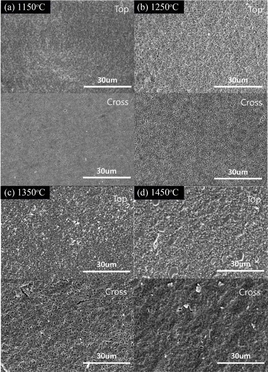
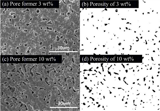
Fig. 2은 각각의 ASL 시편의 단면 SEM 이미지와 Image J 분석 결과를 나타낸다. 3 wt% PMMA를 적용한 시편에서는 평균 약 1.5 μm 크기의 원형 기공이 균일하게 분포하였으며, Porosity는 약 31.5%로 측정되었다. 반면 10 wt% PMMA를 적용한 시편은 평균 2.8 μm 이상의 불규칙하고 Interconnected 형태의 기공들이 상호 연결된 구조를 보였으며, Porosity는 약 51.8%로 증가하였다. 이는 Pore Former의 함량 증가가 기공 연결성과 공극률 증가로 이어지며, 연료 공급에 효율적인 경로를 제공할 수 있음을 시사한다.
Fig. 2SEM images and ImageJ of LST-GDC anode surface at 1250oC, made with (a) and (b) 3 wt%, (c) and (d) 10 wt% pore former
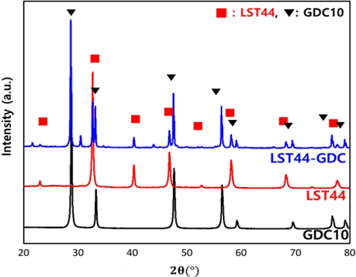
선정된 소결 온도 및 Pore Former 조건을 바탕으로, 열압착된 ASL, AFL Sheet들을 후1250oC에서 공소결하여 연료극 지지체를 제작하였다. 최종적으로 제작된 지지체의 두께는 약 900 um였으며, 단면 SEM 관찰을 통해 상이한 공극률을 가지는 AFL과 ASL 층이 명확히 구분되어 적층된 것을 확인하였다. X-선 회절(XRD) 분석을 통해 소결 후의 결정 구조 변화를 평가한 결과, LST는 전형적인 페로브스카이트 결정 구조를 유지하였으며, GDC는 Cubic Fluorite 구조가 그대로 보존되었다. 이는 두 소재 간의 반응 없이 상 안정성이 유지되었음을 의미한다.
Fig. 3Cross-sectional SEM image of LTS-GDC anode structure composed of ASL and AFL layers
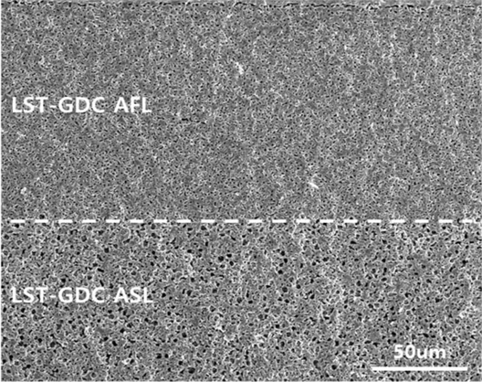
Fig. 4XRD patterns of LTS-GDC anode, LST 44 and GDC10 powder

3.2 연료극 지지체의 전기화학적 특성 평가
전자전도도 특성을 평가하기 위해 Pt 전극을 스퍼터링으로 증착한 후, In-plane 방식으로 500-750
oC에서 전기화학 임피던스 분광법(EIS)을 수행하였다.
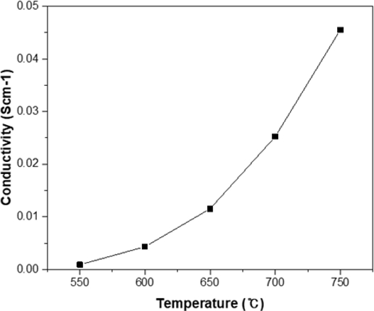
Fig. 5는 온도에 따른 전자전도도 변화를 나타낸다. 온도 증가에 따라 전자전도도는 지수적으로 증가하는 경향을 보였으며, 이는 고온 구동 조건에서 연료극으로서 LST-GDC 복합체의 전도 특성이 충분함을 시사한다.
Fig. 5Temperature dependent electrical conductivities of LST-GDC anode

연료극 지지체의 고체산화물 연료전지(SOFC)로의 적용 가능성을 확인하기 위하여, GDC Buffer Layer, YSZ 전해질, LSCF 공기극을 차례로 증착하여 단전지를 제작하였다. 전해질은 1400
oC에서 소결하였고, 공기극은 950
oC에서 소결하였다. 이때, La 또는 Sr 이 YSZ와 반응하여 SrZrO
3 또는 LaZrO
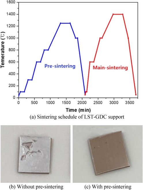
3 등의 부반응 생성물을 억제하기 위해, GDC Buffer Layer를 연료극과 전해질 사이에 도입하였다. LST-GDC 연료극 지지체와 YSZ를 바로 소결할 경우, 열팽창계수 차이로 인해 전해질이 Delamination 되거나 파손되는 문제가 발생하였다(
Fig. 6(b)). 이를 방지하고자 YSZ 전해질에 대해 1250
oC에서 Pre-sintering을 실시한 후, 1400
oC에서 Main Sintering을 수행함으로써(
Fig. 6(a)), 기계적 안정성과 접합 특성이 향상된 구조(
Fig. 6(c))를 확보할 수 있었다.
Fig. 6(a) Sintering schedule for the LST-GDC anode with a YSZ electrolyte. Images of the sintered LST-GDC anode with YSZ electrolyte (b) without pre-sintering, and (c) with pre-sintering
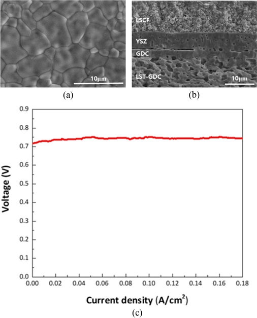
마지막으로, 완성된 Full Cell의 전기화학 성능을 평가한 결과, 750
oC의 작동 온도에서 0.7 V 이상의 안정적인 Open Circuit Voltage (OCV)를 유지하였으며, 연속적인 전류 생성이 확인되었다(
Fig. 7(c)). SEM 분석 결과(
Fig. 7(a)), 전기화학적 평가 이전에 치밀한 YSZ 전해질층이 성공적으로 형성되었음을 확인하였다. 그러나 GDC 버퍼층과 YSZ 전해질층 사이의 계면 접합성이 불충분하여 미세 간극이 존재하는 것으로 판단된다. 이러한 계면 불완전성은 수소와 산소가 전해질 내부에서 부분적으로 혼합되는 가스 크로스오버를 유발하며, 이에 따라 Nernst 전위가 저하되어 약 0.7 V의 낮은 OCV가 관찰된 것으로 해석된다. 위와 같은 이유로 현재 상용 연료극인 NiO-YSZ 기반 셀 대비 상대적으로 낮은 성능을 보이나, GDC Buffer Layer와 YSZ Electrolyte의 화학적, 기계적 접합성을 강화한다면 성능 향상을 달성할 수 있을 것으로 판단됩니다. 본 연구의 LST-GDC 복합 연료극 지지체는 고온에서의 구조 안정성과 전도성 측면에서 고체산화물 연료전지용 연료극으로서의 가능성을 충분히 보여주었다.
Fig. 7(a) SEM image of YSZ electrolyte surface on LST-GDC/GDC, (b) Cross-sectional SEM image of full cell, and (c) Current density vs. voltage of full cell in H2/air 75sccm at 750oC

4. 결론
본 연구에서는 Tape Casting 공정을 활용하여 LST-GDC 기반의 연료극 지지체를 제작하였다. Tape Casting으로 제작된 Sheet의 수를 조절함으로써 지지체의 두께를 손쉽게 제어할 수 있었으며, 동일한 조성의 소재 내에서도 Pore Former의 함량을 조절함으로써 연료 공급에 적합한 다공성 ASL과, 전해질 형성에 유리한 치밀한 AFL로 구성된 이중층 구조를 구현하였다. 또한, 전해질의 치밀한 형성과 연료극과의 계면 접합 특성을 향상시키기 위하여 Pre-sintering 공정을 도입하였다. 연료극과 전해질 사이에서 발생할 수 있는 이차상 형성을 억제하고자 GDC Buffer Layer를 적용하였으며, 이를 통해 고온 소결 조건에서도 구조적 안정성과 전기화학적 성능을 확보할 수 있었다. 제작된 단위셀 750oC의 작동 온도에서 약 0.7 V 이상의 Open Circuit Voltage (OCV)를 안정적으로 유지하며 지속적인 전류 출력을 나타내어, LST-GDC 복합 연료극 지지체의 고체산화물 연료전지(SOFC) 적용 가능성을 입증하였다. 본 연구 결과는 LST 기반 지지체가 기존 Ni 기반 전극 대비 열적·화학적 안정성이 우수하다는 점에서, 수소뿐만 아니라 상용화된 탄화수소 연료를 직접 사용하는 고체산화물 연료전지 시스템 개발에도 활용될 수 있는 가능성을 제시한다.
ACKNOWLEDGMENTS
이 연구는 2021년도 정부(산업통상자원부)의 재원으로 한국에너지기술평가원의 지원을 받아 수행된 연구임(No. 20213030030190, 연료전지 시스템의 스마트설계∙제조∙운전 오픈 플랫폼 개발).
REFERENCES
- 1.
O'hayre, R., Cha, S.-W., Colella, W., Prinz, F. B., (2016), Fuel cell fundamentals, John Wiley & Sons.
10.1002/9781119191766
- 2.
Singh, M., Zappa, D., Comini, E., (2021), Solid oxide fuel cell: Decade of progress, future perspectives and challenges, International Journal of Hydrogen Energy, 46(54), 27643-27674.
10.1016/j.ijhydene.2021.06.020
- 3.
Park, S., Vohs, J. M., Gorte, R. J., (2000), Direct oxidation of hydrocarbons in a solid-oxide fuel cell, Nature, 404(6775), 265-267.
10.1038/35005040
- 4.
McIntosh, S., Gorte, R. J., (2004), Direct hydrocarbon solid oxide fuel cells, Chemical reviews, 104(10), 4845-4866.
10.1021/cr020725g
- 5.
Aguilar, L., Zha, S., Cheng, Z., Winnick, J., Liu, M., (2004), A solid oxide fuel cell operating on hydrogen sulfide (h2s) and sulfur-containing fuels, Journal of Power Sources, 135(1-2), 17-24.
10.1016/j.jpowsour.2004.03.061
- 6.
Will, J., Mitterdorfer, A., Kleinlogel, C., Perednis, D., Gauckler, L., (2000), Fabrication of thin electrolytes for second-generation solid oxide fuel cells, Solid State Ionics, 131(1-2), 79-96.
10.1016/S0167-2738(00)00624-X
- 7.
Su, P.-C., Chao, C.-C., Shim, J. H., Fasching, R., Prinz, F. B., (2008), Solid oxide fuel cell with corrugated thin film electrolyte, Nano Letters, 8(8), 2289-2292.
10.1021/nl800977z
- 8.
Simwonis, D., Tietz, F., Stöver, D., (2000), Nickel coarsening in annealed Ni/8YSZ anode substrates for solid oxide fuel cells, Solid State Ionics, 132(3-4), 241-251.
10.1016/S0167-2738(00)00650-0
- 9.
Abdeljawad, F., Haataja, M., (2013), Microstructural coarsening effects on redox instability and mechanical damage in solid oxide fuel cell anodes, Journal of Applied Physics, 114(18).
10.1063/1.4830015
- 10.
Tanasini, P., Cannarozzo, M., Costamagna, P., Faes, A., Van Herle, J., Hessler‐Wyser, A., Comninellis, C., (2009), Experimental and theoretical investigation of degradation mechanisms by particle coarsening in sofc electrodes, Fuel Cells, 9(5), 740-752.
10.1002/fuce.200800192
- 11.
Homel, M., Gür, T. M., Koh, J. H., Virkar, A. V., (2010), Carbon monoxide-fueled solid oxide fuel cell, Journal of Power Sources, 195(19), 6367-6372.
10.1016/j.jpowsour.2010.04.020
- 12.
Lu, H., Hua, D., Iqabl, T., Zhang, X., Li, G., Zhang, D., (2018), Molecular dynamics simulations of the coke formation progress on the nickel-based anode of solid oxide fuel cells, International Communications in Heat and Mass Transfer, 91, 40-47.
10.1016/j.icheatmasstransfer.2017.11.009
- 13.
Wang, W., Ran, R., Su, C., Guo, Y., Farrusseng, D., Shao, Z., (2013), Ammonia-mediated suppression of coke formation in direct-methane solid oxide fuel cells with nickel-based anodes, Journal of Power Sources, 240, 232-240.
10.1016/j.jpowsour.2013.04.014
- 14.
Niakolas, D. K., (2014), Sulfur poisoning of Ni-based anodes for solid oxide fuel cells in H/C-based fuels, Applied Catalysis A: General, 486, 123-142.
10.1016/j.apcata.2014.08.015
- 15.
Papurello, D., Lanzini, A., Fiorilli, S., Smeacetto, F., Singh, R., Santarelli, M., (2016), Sulfur poisoning in Ni-anode solid oxide fuel cells (SOFCs): Deactivation in single cells and a stack, Chemical Engineering Journal, 283, 1224-1233.
10.1016/j.cej.2015.08.091
- 16.
Hagen, A., Johnson, G. B., Hjalmarsson, P., (2014), Electrochemical evaluation of sulfur poisoning in a methane-fuelled solid oxide fuel cell: Effect of current density and sulfur concentration, Journal of Power Sources, 272, 776-785.
10.1016/j.jpowsour.2014.08.125
- 17.
Sarıboğa, V., Öksüzömer, M. F., (2016), Cu-CeO2 anodes for solid oxide fuel cells: Determination of infiltration characteristics, Journal of Alloys and Compounds, 688, 323-331.
10.1016/j.jallcom.2016.07.217
- 18.
Toscani, L. M., Troiani, H., Lamas, D. G., Larrondo, S. A., Mogni, L. V., (2023), Ni-free CeO2-ZrO2-Sc2O3 nanostructured fuel electrodes for high performance solid oxide cells, Electrochimica Acta, 462, 142781.
10.1016/j.electacta.2023.142781
- 19.
Sfeir, J., (2003), LaCrO3-based anodes: Stability considerations, Journal of Power Sources, 118(1-2), 276-285.
10.1016/S0378-7753(03)00099-5
- 20.
Venâncio, S. A., de Miranda, P. E. V., (2023), Ni-free SOFC anode material with thermal and redox stabilities for the direct utilization of ethanol, Catalysts, 13(1), 134.
10.3390/catal13010134
- 21.
Yoo, K. B., Choi, G. M., (2009), Performance of La-doped strontium titanate (LST) anode on LaGaO3-based SOFC, Solid State Ionics, 180(11-13), 867-871.
10.1016/j.ssi.2009.02.013
- 22.
Zhou, X., Yan, N., Chuang, K. T., Luo, J., (2014), Progress in La-doped SrTiO3 (LST)-based anode materials for solid oxide fuel cells, Rsc Advances, 4(1), 118-131.
10.1039/C3RA42666A
- 23.
Yoo, K. B., Park, B. H., Choi, G. M., (2012), Stability and performance of SOFC with SrTiO3-based anode in CH4 fuel, Solid State Ionics, 225, 104-107.
10.1016/j.ssi.2012.05.017
- 24.
Yoo, K. B., Choi, G. M., (2011), LST-GDC composite anode on LaGaO3-based solid oxide fuel cell, Solid State Ionics, 192(1), 515-518.
10.1016/j.ssi.2010.06.048
- 25.
Fan, L., Wang, Y., Huo, H., Xiong, Y., (2013), Performance of lst-gdc composite anodes for solid oxide fuel cells, ECS Transactions, 57(1), 1193.
10.1149/05701.1193ecst
- 26.
Fan, L., Xiong, Y., Liu, L., Wang, Y., Kishimoto, H., Yamaji, K., Horita, T., (2014), Performance of Gd0.2Ce0.8O1.9 infiltrated La0.2Sr0.8TiO3 nanofiber scaffolds as anodes for solid oxide fuel cells, Journal of Power Sources, 265, 125-131.
10.1016/j.jpowsour.2014.04.109
- 27.
Yang, C., Jing, X., Miao, H., Xu, J., Lin, P., Li, P., Liang, C., Wu, Y., Yuan, J., (2021), The physical properties and effects of sintering conditions on rSOFC fuel electrodes evaluated by molecular dynamics simulation, Energy, 216, 119215.
10.1016/j.energy.2020.119215
- 28.
Fan, L., Wang, Y., Jia, Z., Xiong, Y., Brito, M. E., (2015), Nanofiber-structured SSC-GDC composite cathodes for a LSGM electrolyte based IT-SOFCs, Ceramics International, 41(5), 6583-6588.
10.1016/j.ceramint.2015.01.104
- 29.
Kim, S. D., Hyun, S. H., Moon, J., Kim, J.-H., Song, R. H., (2005), Fabrication and characterization of anode-supported electrolyte thin films for intermediate temperature solid oxide fuel cells, Journal of Power Sources, 139(1-2), 67-72.
10.1016/j.jpowsour.2004.07.013
Biography
- Min Ji Kim
Ph.D. candidate in the Department of Mechanical Convergence Engineering, Hanyang University. Her research is about the electrode fabrication and interface of all solid batteries.
- Chunghyun Kim
Ph.D. candidate in the Department of Mechanical Convergence Engineering, Hanyang University. His research is about the fuel cell for hydrogen vehicle and solid oxid fuel cell.
- Young-Beom Kim
Professor in the Department of Mechanical Convergence Engineering, Hanyang University. His research interests include development of various solid-state energy conversion devices including solid oxide fuel cells, all-solid-state batteries etc.