ABSTRACT
This study details the development of an ultra-precision air-bearing stage that integrates real-time motion error measurement and compensation features. The motion errors addressed include horizontal and vertical straightness errors, as well as roll, pitch, and yaw errors. These errors are measured by an embedded system that incorporates five capacitive sensors and a reference mirror within the stage. A key advantage of this stage is its capability to perform real-time compensation using the internal measurement system and on-stage pneumatic regulators, eliminating the need for external measurement and compensation devices. Experimental results show a significant reduction in motion errors, with horizontal and vertical straightness errors decreasing from 3.09 and 1.95 μm to 0.29 and 0.25 μm, respectively. Additionally, roll, pitch, and yaw errors were reduced from 3.18, 3.45, and 4.93 arcsec to 0.35, 0.41, and 0.49 arcsec, respectively. These results clearly demonstrate the effectiveness of the proposed approach.
-
KEYWORDS: Air-bearing, Capacitive sensor, Motion error, Real-time measurement, Compensation
-
KEYWORDS: 에어베어링, 정전용량 센서, 운동 오차, 실시간 측정, 보정
NOMENCLATURE
Left Side Levitation Force of the Stage [N]
Right Side Levitation Force of the Stage [N]
Magnetic Attractive Force [N]
Distance from the Permanent Magnet to Center [mm]
Distance from the Air-bearing to t Center [mm]
Measured Data of i-th Sensor, (i=1,...,5) [μm]
Distance between the First and Second Sensors [mm]
Height between m3 and m5 [mm]
Linear Displacement Error [μm]
Horizontal Straightness Error [μm]
Vertical Straightness Error [μm]
1. 서론
최근 산업의 고도화에 따라 초정밀 부품에 대한 수요가 지속적으로 증가하고 있다. 반도체 제조 및 정밀 계측 장치 분야에서는 스테이지의 성능이 제품 품질에 직접적인 영향을 미치기 때문에, 높은 정밀도를 확보할 수 있는 초정밀 스테이지를 사용한다[
1,
2]. 특히 웨이퍼 노광(Wafer Photolithography) 공정에서 초정밀도 확보의 핵심 요소로 에어베어링 스테이지가 활용된다[
3].
에어베어링 스테이지는 마찰이 거의 없는 부상 상태에서 구동되므로, 높은 분해능(Resolution)과 재현성(Repeatability)을 제공하여 초정밀 구동에 적합하다. 하지만 에어베어링 스테이지는 이송 중 운동 오차를 나타내며, 이러한 오차를 정밀하게 측정하고 보정하는 것이 필요하다[
4].
일반적으로 오차 보정 방식은 하드웨어 방식과 소프트웨어 방식으로 나뉜다. 하드웨어 방식은 완성된 스테이지의 운동 오차를 측정하고, 운동 오차가 기준을 초과하는 경우 구성품을 수정가공 및 재조립하는 과정을 반복하여 기준을 충족시키는 방법이다[
5]. 반면에 소프트웨어 방식은 스테이지의 운동 오차를 측정하고 체적 오차를 계산한 후 제어기에서 보정하는 방법으로 하드웨어 방식에 비해 유연하며 실시간 보정에 유리하다. 초정밀 스테이지의 운동 오차는 레이저 간섭계(Laser Interferometer)와 정전용량 센서(Capacitive Sensor)등을 사용하여 측정하고 있으나, 사전에 측정한 값을 제어기에서 보정하기에 실시간 측정 및 보정이 제한된다[
6].
따라서 본 연구는 초정밀 스테이지의 성능 향상을 목표로 운동 오차의 실시간 측정과 보정 기능이 통합된 에어베어링 스테이지를 개발한다. 스테이지의 운동 오차는 스테이지 내부에 설치된 5개의 정전용량 센서와 기준 미러(Reference Mirror)를 사용하여 측정한다. 측정된 오차는 스테이지 에어베어링의 압력 조절을 통해 보정한다.
2. 에어베어링 스테이지 설계
2.1 스테이지 구조 설계
본 연구에서 제안한 에어베어링 스테이지는
Table 1에 명시된 주요 구성 요소들을 기반으로
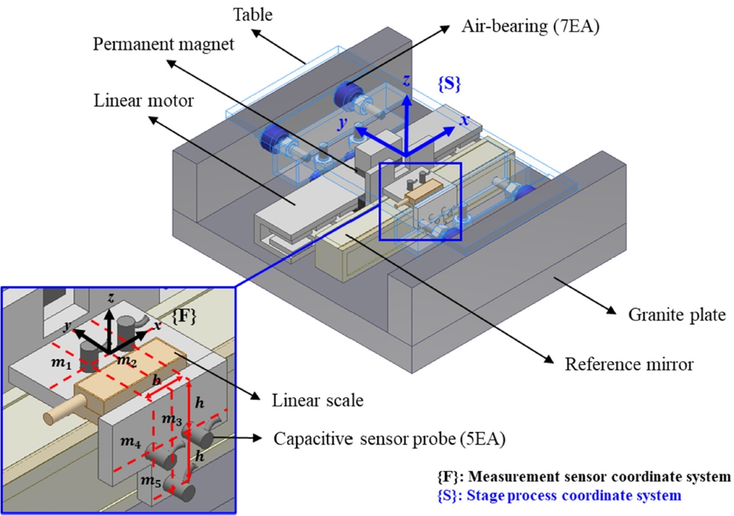
Fig. 1과 같이 제작되었다.
스테이지의 구조적 안정성을 확보하고 흔들림(Rocking) 문제를 방지하기 위해,
Fig. 2와 같이 스테이지의 수직 방향 에어베어링을 3점 지지 구조(Three-point Support)로 채택하였다[
7].
에어베어링의 부상력(Air Levitation Force)에 대응하여 네오디뮴(Neodymium)을 주성분으로 이루어진 영구 자석(Permanent Magnet)의 흡착력(Magnetic Attractive Force)을 예압(Preload)으로 활용하였다[
1].
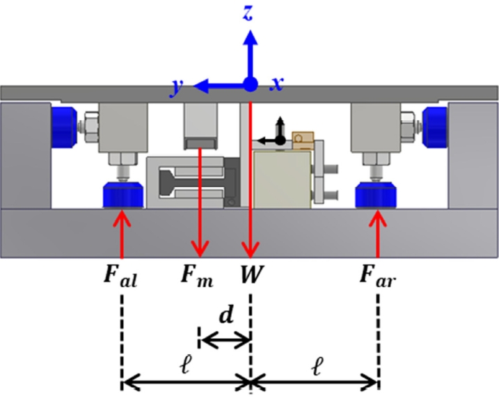
영구 자석의 설치 위치는 스테이지 테이블의 무게와 에어베어링 위치를 고려하여 결정하였다. 스테이지 예압은
Fig. 3에 나타난 바와 같이 영구 자석을 배치하여 형성하였다.
힘과 모멘트의 평형식은 각각
식(1),
식(2)와 같으며, 영구 자석 간의 최적 거리 d를
식(3)과 같이 도출하였다.
스테이지 시스템은 오차 측정 기능을 담당하는 센서 모듈(Sensor Module), 구동 및 위치 제어를 수행하는 제어 모듈(Control Module), 에어베어링에 압축공기를 공급하는 공압 모듈(Pneumatic Module)로
Fig. 4와 같이 구성하였다.
센서 모듈에서 정전용량 센서 5개와 기준 미러를
Fig. 1에서 확대된 부분과 같이 스테이지 내부에 설치하였다. ㄱ자 형태의 측정 지그(Jig)를 사용하여 기준 미러의 상단에는 센서 2개, 측면에는 센서 3개를 배치하였다. Lee 등[
6,
8-
11]이 제안한 측정 좌표계와 정전용량 센서 간의 위치를 최적화하는
식(4)을 응용하여, 센서의 위치와 측정 좌표계를 설정하여 측정불확도를 최소화하였다.
식(4)에서 사용되는
mi값은 정전용량 센서의 출력 전압 신호를 변위로 환산한 값이다.
제어 모듈은 PMAC (Programmable Multi Axis Controller) 제어기와 리니어 모터(Linear Motor), 리니어 엔코더(Linear Encoder)로 구성하였다.
공압 모듈은 메인 공압 레귤레이터(Pneumatic Regulator, SMC Corporation, Japan, Max. set pressure 1.0 MPA(10 bar))를 통해 스테이지의 에어베어링에 공압을 공급하였다. 특히,
Fig. 2에서 나타낸 바와 같이 스테이지 각 측면에 배치된 4개의 베어링(1번, 2번, 5번, 6번)은 각각 독립된 공압 레귤레이터에 연결하고, 바닥면에 위치한 2개의 베어링(3번, 4번)은 좌우로 구분하여 각각 공압 레귤레이터를 연결하였다.
에어베어링 스테이지의 오차 보정을 위해, 먼저 스테이지를 X 방향으로 구동하면서 수평 및 수직 진직도, 롤, 피치, 요 오차를 정전용량 센서를 이용하여 실시간 측정하였다. 이후, 측정된 오차 데이터를 알고리즘에 적용하여 보정 값을 산출하였다.
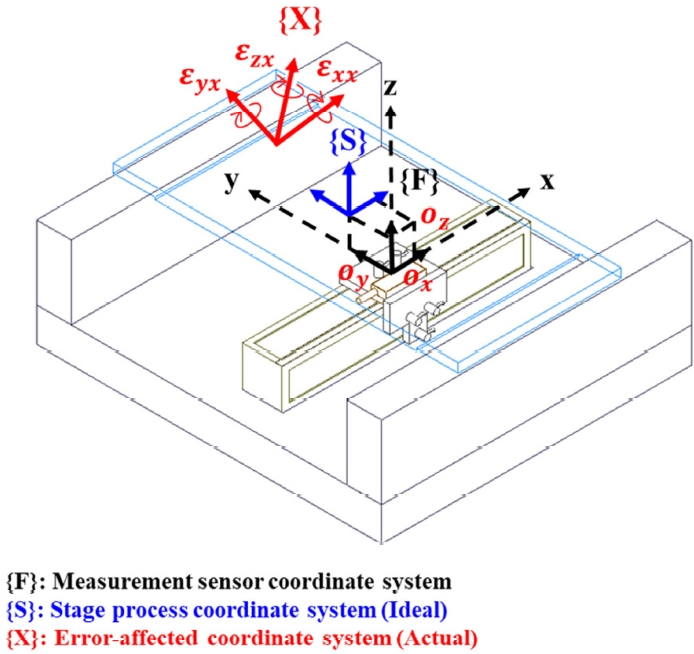
스테이지의 좌표계 구성은 ISO 230-1[
12] 표준 규격과 Lee 등[
6,
13-
16]의 연구 결과를 적용하였다
Fig. 5에서 나타낸 바와 같이 측정 센서 좌표계 {F}, 스테이지 공정 좌표계 {S}, 오차가 반영된 좌표계{X}로 정의하였다.
측정 센서 좌표계에서 스테이지 공정 좌표계까지 두 좌표계 사이 기준 위치 차이(Offset)인
ox, ov, oz를 곱하여, 오차 동차 변환 행렬(Homogeneous Transformation Matrix)로 나타내면
식(5)와 같다.
여기서 Δx, Δy, Δz는 각각 X, Y, Z 방향의 운동 오차를 나타내며,
식(7)과 같다.
본 연구에서는 Roh 및 Shin 등[
17,
18]이 제안한 공압 기반 정밀 제어 원리를 응용하여, 공압 레귤레이터를 활용한 오차 보정 시스템을 구현하였다.
Fig. 6에 나타낸 알고리즘으로 산출된 보정 값은 공압 모듈을 통해 공압 레귤레이터로 전달되어 스테이지 위치를 정밀하게 조정한다. 스테이지의 오차가 적절히 보정되었는지 검증하기 위해 보정 후 운동 오차를 다시 측정하였다. 이때 오차 값이 0.5 μm 이하이면 알고리즘을 종료하였으며, 0.5 μm를 초과할 경우 오차 측정 단계로 돌아가 알고리즘을 반복 수행하였다.
Fig. 2에 나타난 바와 같이 공압 레귤레이터를 통해 에어베어링 1, 2, 5, 6번의 공압을 조절하여 스테이지의 Y방향 운동 오차를 보정하고, 에어베어링 3, 4번의 공압을 조절하여 스테이지의 Z방향 운동 오차를 보정하였다.
3. 실험 및 결과
3.1 공압을 활용한 오차 보정 성능 실험
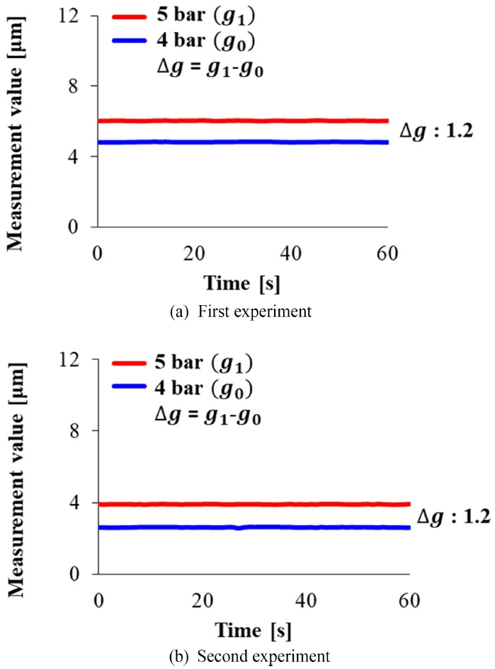
스테이지의 오차 보정을 위한 기초 실험으로, 공압 변화에 따른 에어 갭(Air gap) 변화를 측정하였다. 스테이지에 4 bar (g0)의 공압을 기준으로 설정한 후, 공압을 5 bar (g1)로 증가시켜 각 상태에서 정전용량 센서를 이용하여 각 에어 갭을 측정하였다.
실험은 스테이지가 보정되지 않은 상태에서 반복 수행되었으며, 측정 위치에 따라 1차와 2차로 나누어 진행하였다. 1차 실험은 스테이지 시작점에서 측정하고 2차 실험은 스테이지를 10 mm 이동한 다른 지점에서 수행하였다. 각 위치에서 공압 변화에 따른 에어 갭 변화를 60초 동안 측정하였다.
Figs. 7(a)와
7(b)에서 4 bar 기준 에어 갭 값이 서로 다르게 나타나는데, 이는 측정 위치에 따른 석정반의 평탄도(Flatness)에 의한 영향이다.
공압이 4 bar일 때와 5 bar일 때의 에어 갭 차이(∆g = g
1-g
0)는 1 bar에 해당하는 공압 변화에 따른 기준값으로 활용된다.
Fig. 6과 같이 제안한 스테이지의 경우, 4와 5 bar 압력 조건에서 평균적으로 1 bar당 약 1.2 μm의 에어 갭이 발생함을 확인하였다.
운동 오차 측정은 스테이지의 총 이동 거리(Stroke) 100 mm 이송과 동시에 실시간으로 수행되었으며 이송 속도는 10 mm/s 설정하였다.
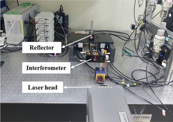
스테이지의 구동 방향인 X방향의 선형 변위 오차(Linear Displacement Error)는 설치된 정전용량 센서로 측정할 수 없기 때문에
Fig. 8과 같이 레이저 간섭계(XL80; Renishaw Plc., UK)를 사용하여 측정하였다. 측정한 데이터를 사용하여 수정한 제어 위치를 기반으로 오차 보정을 수행하였다.
정전용량 센서로 측정된 운동 오차 값은 제안한 알고리즘을 통해 Y, Z방향에 해당하는 보정 값 산출에 사용하였으며, 산출 된 보정 값을 사용하여 각 방향에 대응되는 에어베어링의 공압을 조절하였다. 오차에 따라 공압을 실시간으로 제어하였으며, 보정 결과는 정전용량 센서를 통해 재 측정하여 평가하였다. 또한 운동 오차 측정 신뢰성을 확보하기 위해, 실험은 10회 반복 수행하였다.
스테이지의 오차 보정 성능은
Fig. 9와 나타낸 바와 같이 현저히 개선되었으며, 반복 측정한 오차의 PV (Peak-to-Valley)값에 대한 평균과 표준편차는
Table 2에 제시되어 있다.
선형 변위 오차는 PV값이 0.7에서 0.03 μm로 약 96% 감소하였으며, 진직도 오차는 수평 방향이 3.09에서 0.29 μm로 약 91%, 수직 방향이 1.95에서 0.25 μm로 약 87% 감소하여 우수한 보정 성능을 확인하였다.
회전 오차의 경우 롤, 피치, 요 오차가 각각 3.18에서 0.35 arcsec로 약 89%, 3.45에서 0.41 arcsec로 약 88%, 4.93에서 0.49 arcsec로 약 90% 감소하여 효과적인 보정이 이루어졌다.
4. 결론
본 연구에서는 에어베어링 스테이지의 운동 오차를 실시간으로 측정하고 보정하는 기능이 통합된 초정밀 스테이지 시스템을 개발하였다. 정전용량 센서를 이용하여 실시간으로 운동 오차를 측정하고, 에어베어링의 공압을 제어함으로써 오차를 보정하는 방식을 제안하였다.
제안된 스테이지는 측정 및 보정 기능을 하나의 통합 구조로 구현함으로써 전체 시스템의 구조적 단순화뿐만 아니라 실시간 오차 보정 기능의 유효성을 확보하였다. 실험 결과, 87% 이상의 오차 감소율을 달성하였으며, 이는 제안한 스테이지의 오차 보정 알고리즘이 효과적인 것을 실험적으로 확인하였다.
향후 연구에서는 제안된 스테이지의 산업 적용 확대를 위해 10 mm/s 이상의 이송 속도에서 동적 응답 특성을 분석하여 보정 성능을 유지할 수 있는 스테이지 시스템을 개발하고자 한다.
Fig. 1Isometric view of the air-bearing stage

Fig. 2Top view of the air-bearig stage
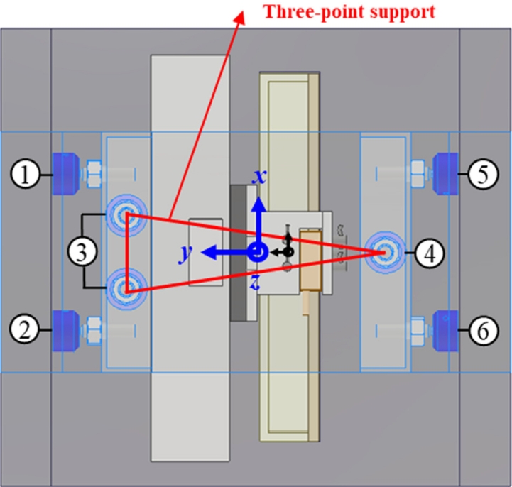
Fig. 3Front view of the air-bearing stage

Fig. 4System configuration of the air-bearing stage
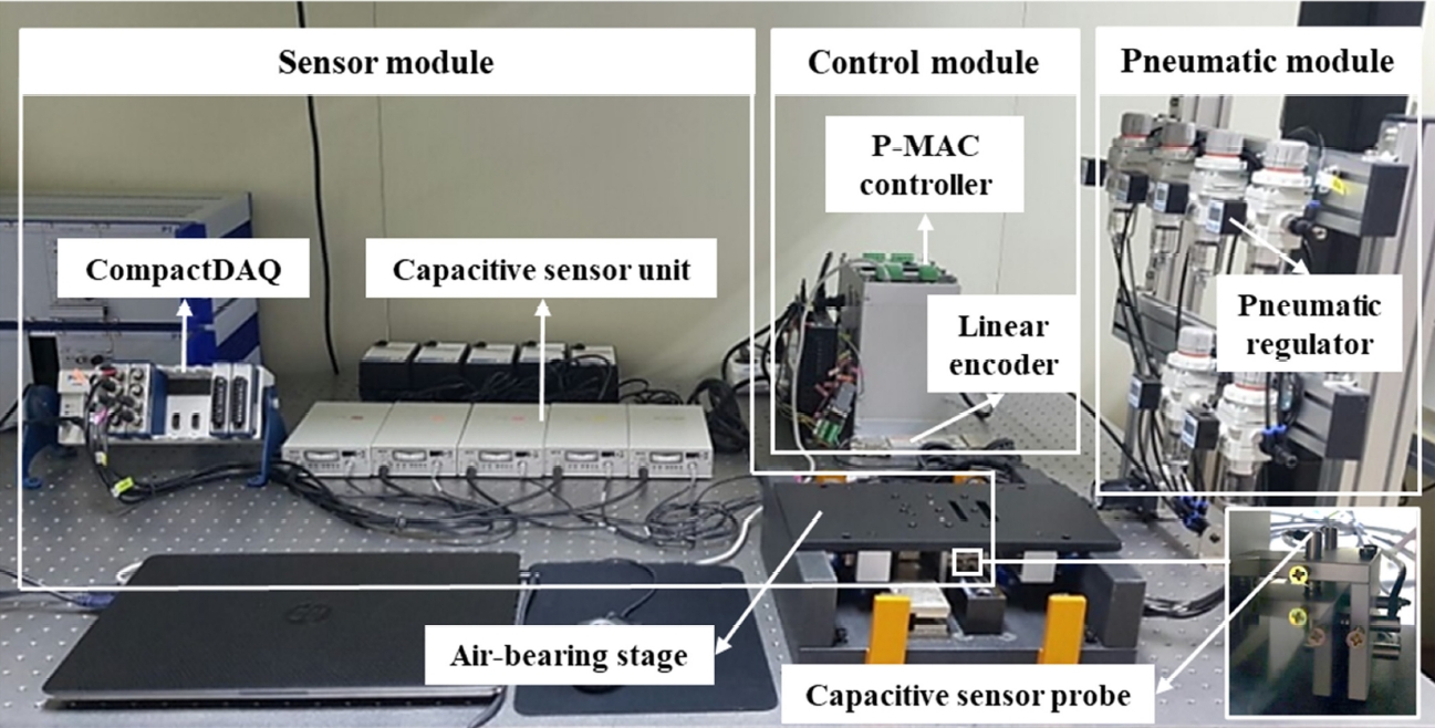
Fig. 5Coordinate system of the air-bearing stage

Fig. 6Compensation algorithm of the air-bearing stage
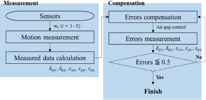
Fig. 7Air gap variation between 4 and 5 bar

Fig. 8Experimental environment for linear displacement error measurement using laser interferometer

Fig. 9Results of motion errors compensation
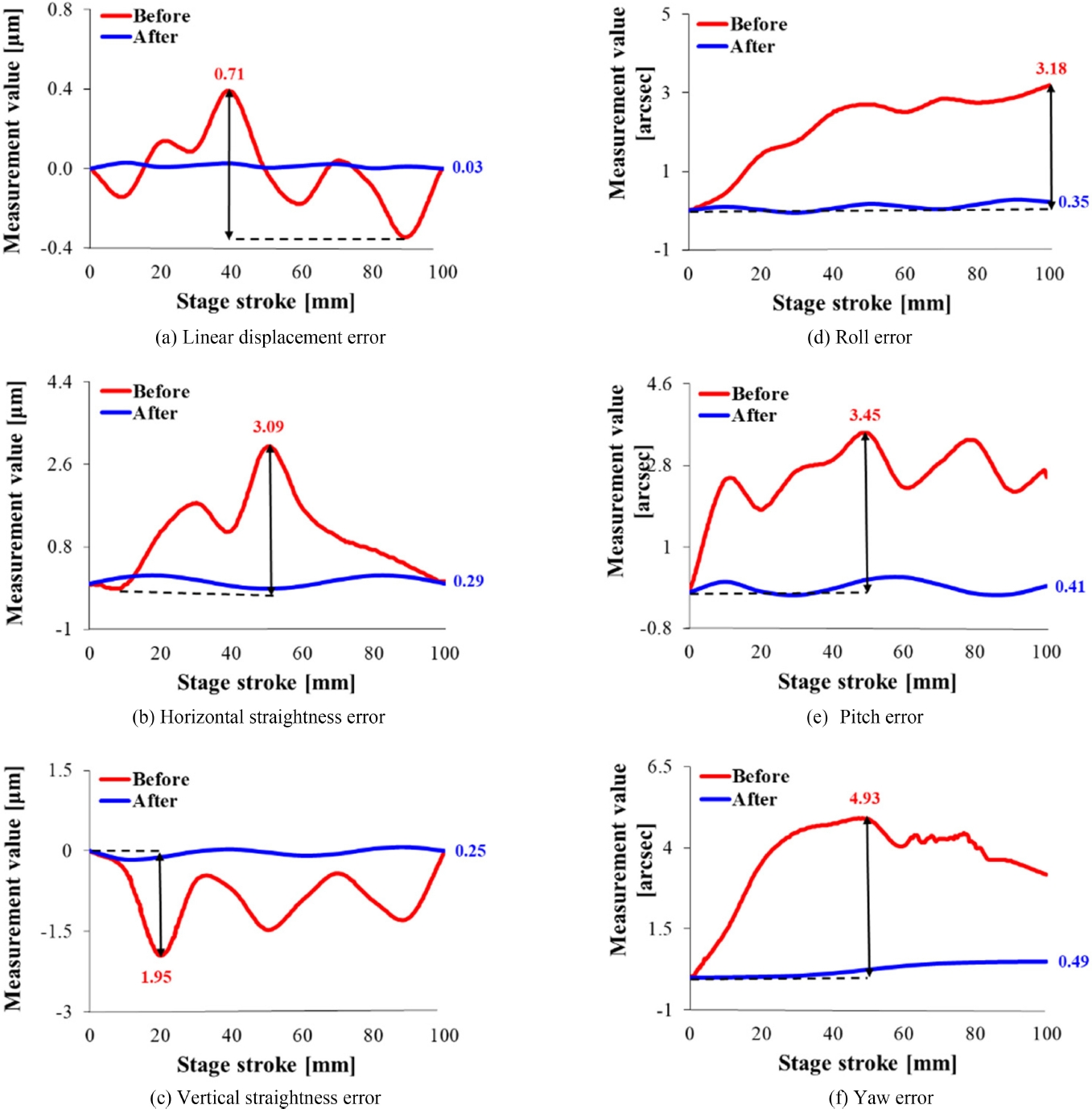
Table 1.Components of the air-bearing stage
Table 1.
|
Name |
Features |
Manufacturer |
|
Air-bearing |
Porous type, ϕ25 mm round |
LNK Co., Ltd., Republic of Korea |
|
Linear encoder |
Resolution: 5 nm |
Renishaw Plc., United Kingdom |
|
Granite plate |
Flatness: 2 μm, Squareness: 1 μrad |
Mikro Mi Tech Co., Ltd., Republic of Korea |
|
Reference mirror |
Coated with conductive layers |
Charm-Tech Co., Ltd., Republic of Korea |
Table 2.Compensation results of motion errors
Table 2.
|
Parameters |
Compensation
|
Reduction [%] |
|
Before |
After |
|
PV Mean ± Standard deviation |
|
δxx [μm] |
0.71 ± 0.03 |
0.03 ± 0.01 |
95.77 |
|
δyx [μm] |
3.09 ± 0.13 |
0.29 ± 0.02 |
90.61 |
|
δzx [μm] |
1.95 ± 0.10 |
0.25 ± 0.02 |
87.18 |
|
εxx [arcsec] |
3.18 ± 0.13 |
0.35 ± 0.03 |
89.00 |
|
εyx [arcsec] |
3.45 ± 0.12 |
0.41 ± 0.04 |
88.12 |
|
εzx [arcsec] |
4.93 ± 0.14 |
0.49 ± 0.04 |
90.06 |
REFERENCES
- 1. Ro, S.-K., Kim, S., Kwak, Y., Park, C. H., (2010), A linear air bearing stage with active magnetic preloads for ultraprecise straight motion, Precision Engineering, 34(1), 186-194.
- 2. Tian, C., Ming, Z., Yu, Z., Chuxiong, H., (2011), Dynamic modeling and analysis of a 3-dof ultra-precision positioning stage with air bearing, Procedia Engineering, 16, 264-270.
- 3. Lee, C.-W., Kim, S.-W., (1997), An ultraprecision stage for alignment of wafers in advanced microlithography, Precision Engineering, 21(2-3), 113-122.
- 4. Gao, W., Arai, Y., Shibuya, A., Kiyono, S., Park, C. H., (2006), Measurement of multi-degree-of-freedom error motions of a precision linear air-bearing stage, Precision Engineering, 30(1), 96-103.
- 5. Ryu, D., Lee, J. H., Park, S.-S., Kim, G. H., (2020), Effect of shape error of an air stage on motion precision, Tribology and Lubricants, 36(2), 68-74.
- 6. Lee, J.-C., Yang, S.-H., (2017), Development of nanopositioning mechanism with real-time compensation algorithm to improve the positional accuracy of a linear stage, Precision Engineering, 50, 328-336.
- 7. Elliott, R., (2003), The principles of model locomotive suspension, Scalefour digest 41.0, Issue 2. http://www.clag.org.uk/41-0rev.html.
- 8. Lee, J. H., Liu, Y., Yang, S.-H., (2006), Accuracy improvement of miniaturized machine tool: geometric error modeling and compensation, International Journal of Machine Tools and Manufacture, 46(12-13), 1508-1516.
- 9. Lee, K.-I., Lee, J.-C., Yang, S.-H., (2013), The optimal design of a measurement system to measure the geometric errors of linear axes, The International Journal of Advanced Manufacturing Technology, 66, 141-149.
- 10. Lee, J.-C., Lee, K.-I., Yang, S.-H., (2014), Performance evaluation of five-dof motion under static and dynamic conditions of ultraprecision linear stage, Journal of the Korean Society for Precision Engineering, 31(5), 423-430.
- 11. Lee, H.-H., Lee, I.-S., Lee, K.-I., Yang, S.-H., (2021), Development and performance evaluation of a fine stage for compensating 6-DOF motion errors of an ultra-precision linear stage, Journal of the Korean Society for Precision Engineering, 38(2), 123-129.
- 12. ISO 230-1, (2012), Test code for machine tools – Part 1: Geometric accuracy of machines operating under no-load or quasi-static conditions, Third edition.
- 13. Lee, J. H., Yang, S. H., (2005), Measurement of geometric errors in a miniaturized machine tool using capacitance sensors, Journal of Materials Processing Technology, 164-165, 1402-1409.
- 14. Lee, K.-I., Lee, D.-M., Kweon, S.-H, Yang, S.-H., (2010), Geometric errors estimation of a rotary table using double ball-bar, Journal of the Korean Society for Precision Engineering, 27(11), 98-105.
- 15. Lee, D.-M., Zhu, Z., Lee, K.-I., Yang, S.-H., (2011), Identification and measurement of geometric errors for a five-axis machine tool with a tilting head using a double ball-bar, International Journal of Precision Engineering and Manufacturing, 12, 337-343.
- 16. Lee, J.-C., Lee, H.-H., Yang, S.-H., (2016), Total measurement of geometric error of a three-axis machine tool by developing the hybrid technique, International Journal of Precision Engineering and Manufacturing, 17, 427-432.
- 17. Roh, C.-H., Kim, Y.-S., (2001), Development of the smalldisplacement-movement of a pneumatic piston and the hybrid control algorithm for precision position control, Journal of the Korean Society for Precision Engineering, 18(7), 40-45.
- 18. Shin, J.-M., Ahn, H.-J., (2024), Active control of pneumatic vibration isolator with pressure observer, Journal of the Korean Society for Precision Engineering, 41(3), 169-174.
Biography
- Eun Young Ko
Ph.D Student in School of Mechanical Engineering, Kyungpook National University. Her research interest are intelligent manufacturing systems, pre-cision engineering and robot.
- Hoon Hee Lee
Senior Researcher in Precision Mechanical Process and Control R&D Group, Korea Institute of Industrial Technology. His research interest are machine tool metrology and precision process control.
- Kwang Il Lee
Professor in School of Mechanical and Automotive Engineering, Kyungil University. His research interests are precision methodologies for machine tools and 3D printer.
- Seung Han Yang
Professor in School of Mechanical Engineering, Kyungpook National University. His research interests are intelligent manufacturing systems and CAD/CAM.